
87 monte ss - Air Power
Air Compressor Rebuild
|
Source
|
Item
|
Cost
|
|---|---|---|
| Craig's List | 1945 DeVilbiss Air Compressor | $275 |
| Master Machine Works | Hone block, press off bearings | $125 |
| Midway Auto Parts | Brake cylinder hone | $15 |
| Fleece Bay | 2 New Departure (NDH) 3306 bearings | $31 |
| Fleece Bay | National 450160 Oil Seal (free shipping) | $11 |
| Woodward Compressor Sales | Ring Set Valve Kit Klinger gaskets 1/16 | $139 |
| JW Vaughan | Pair of matched V-belts | $17 |
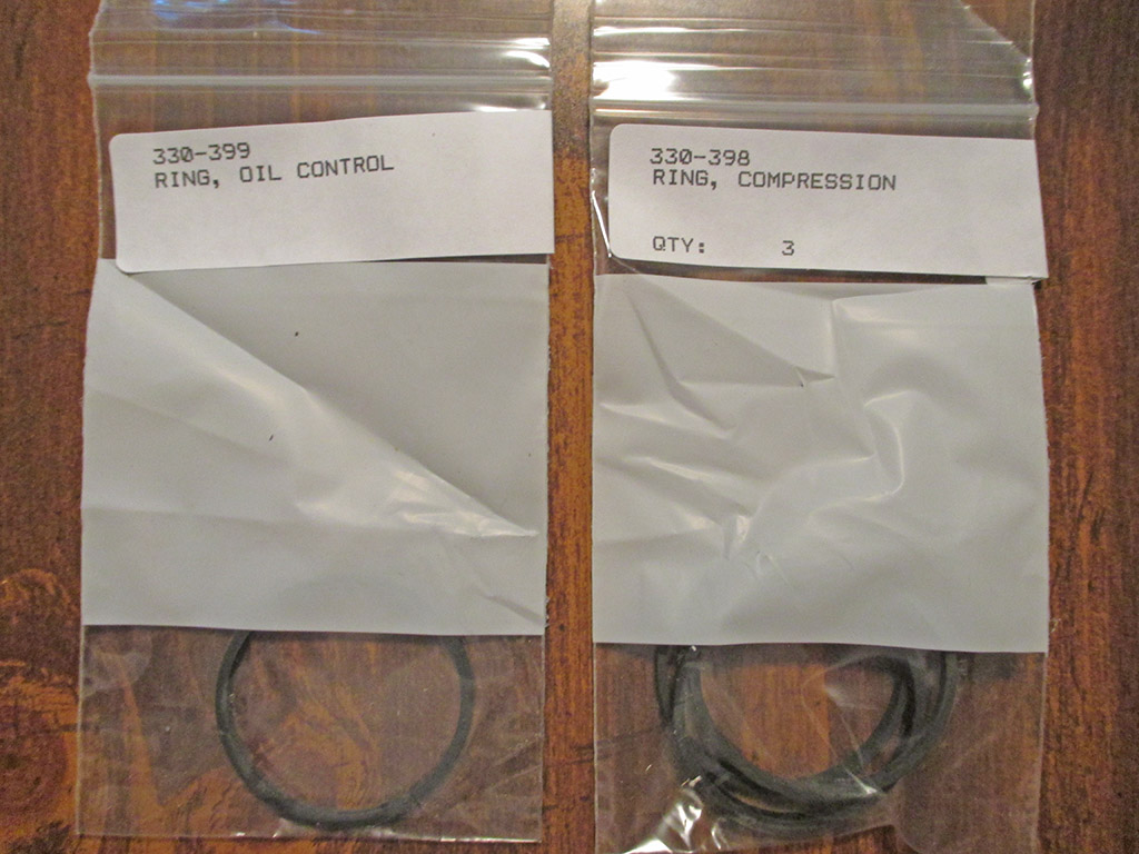
| Woodward Compressor Sales | Piston Rings - (4@ $10.50) + | $56 |
| Lowe's | Copper Pipe/Fittings, Electrical | $205 |
| Fleece Bay | Apollo Ball Valves | $45 |
| Fleece Bay | Solder | $25 |
| Fleece Bay | Wilkerson Pressure Regulator | $50 |
| Fleece Bay | Wilkerson Coalescing Air Filter | $90 |
| Fleece Bay | Wilkerson Brackets | $56 |
| Lowe's | High Pressure Flex Line | $20 |
| Lowe's | Apollo 1/2 Inch Ball Valve | $14 |
| Sandblasting & Painting | Had pump sandblasted | $35 |
| Total | 1,207.78 |
If you want a quality air compressor, you have few choices. You can pony up big bucks for a quality unit like Quincy, Kellogg or Saylor-Beall.
Or... if you have the time/talent you can scrounge up an older "made in USA" unit, roll up your sleeves and refurbish it. This is the path I decided to go down to get a quality machine for minimal cash outlay. Now let's see if I can pull it off.
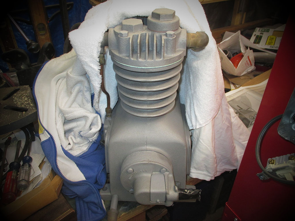
I found an old DeVilbiss unit on the list that is Craig's and dragged it home. All I need now are the proper parts... for a compressor made a long, long time ago.
If you're going to do any sort of work at all on vehicles, it makes sense to work as efficiently as possible. To this end, most folks who do this as a hobby soon discover the advantages of using air tools (less weight than electric tools) and soon add them to their tool arsenal. The key ingredient of course is an air compressor which fills a storage tank with compressed air to run all the air tools. I'm currently using an "oilless screamer" type, but have outgrown the CFM (cubic feet per minute) it can provide. Long story short... I need a bigger compressor.
![]()
1970's home-brewed compressor
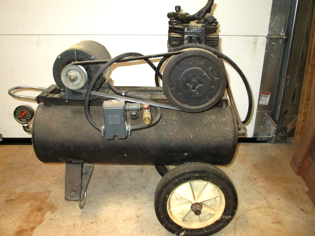
My Uncle Ray pieced this together from a big-rig air tank, a Lincoln A/C compressor and an electric motor. It wasn't much, but it beat filling tires with a handpump, which was all we had at the time. This was mainly for my bike's tires or the tractor tires. If the car's tires got too low, you stopped at a service station and filled them there... for free! A different time to be sure.
The only issue with this unit was trying to start it up again after the first cycle. The electric motor began having issues pumping against a partially full tank. In recent years, I tried to re-power it with other motors, but I didn't have the cash to purchase a new motor and the used ones I tried just didn't cut the mustard. Needless to say, running high-demand air tools was out of the question.
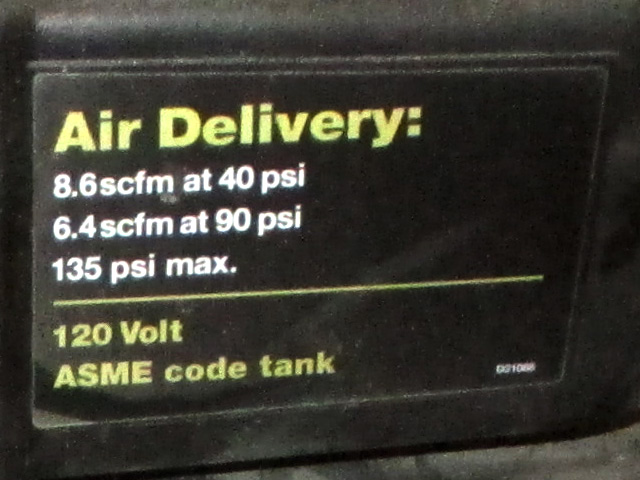
Santa was very generous one year and left this under our tree. This worked pretty good for some of the air tools I'd acquired over the years. The advantage of this compressor was its requirement for 120 volts AC. The downside? Well, for the longest time I couldn't run it continuously due to inadequate circuits in my shop. I cured this with a dedicated 30 amp circuit just for the compressor.
Another thing about this unit was the noise. When running this in my shop I wear headphone style hearing protection. Yeah, it is LOUD! When I used it with my spray gun to lay primer on the roof of my van, it ran constantly. Obviously something had to be done. Unless you have really deep pockets, most any compressor you can find is made in China. Nope, not interested.
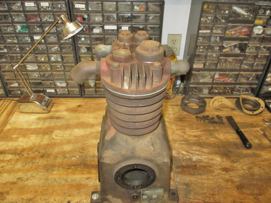
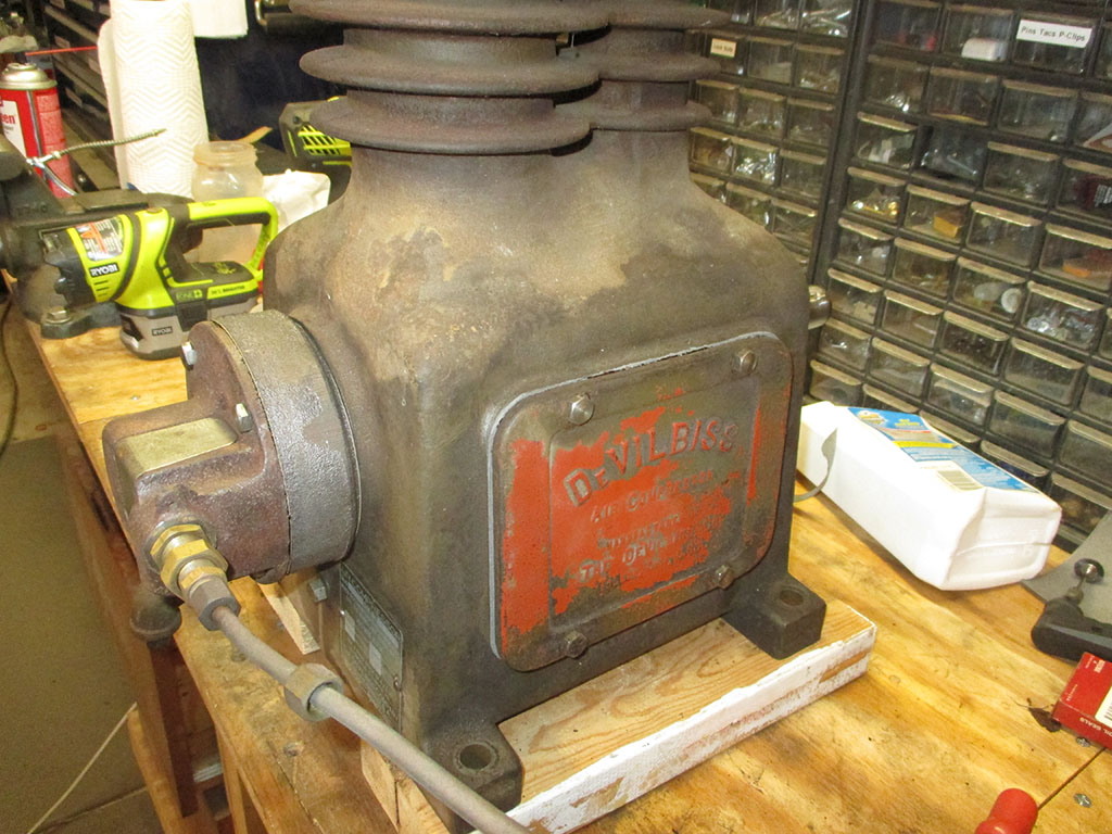
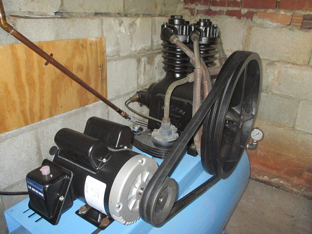
Enter the Devilbiss 330 Compressor
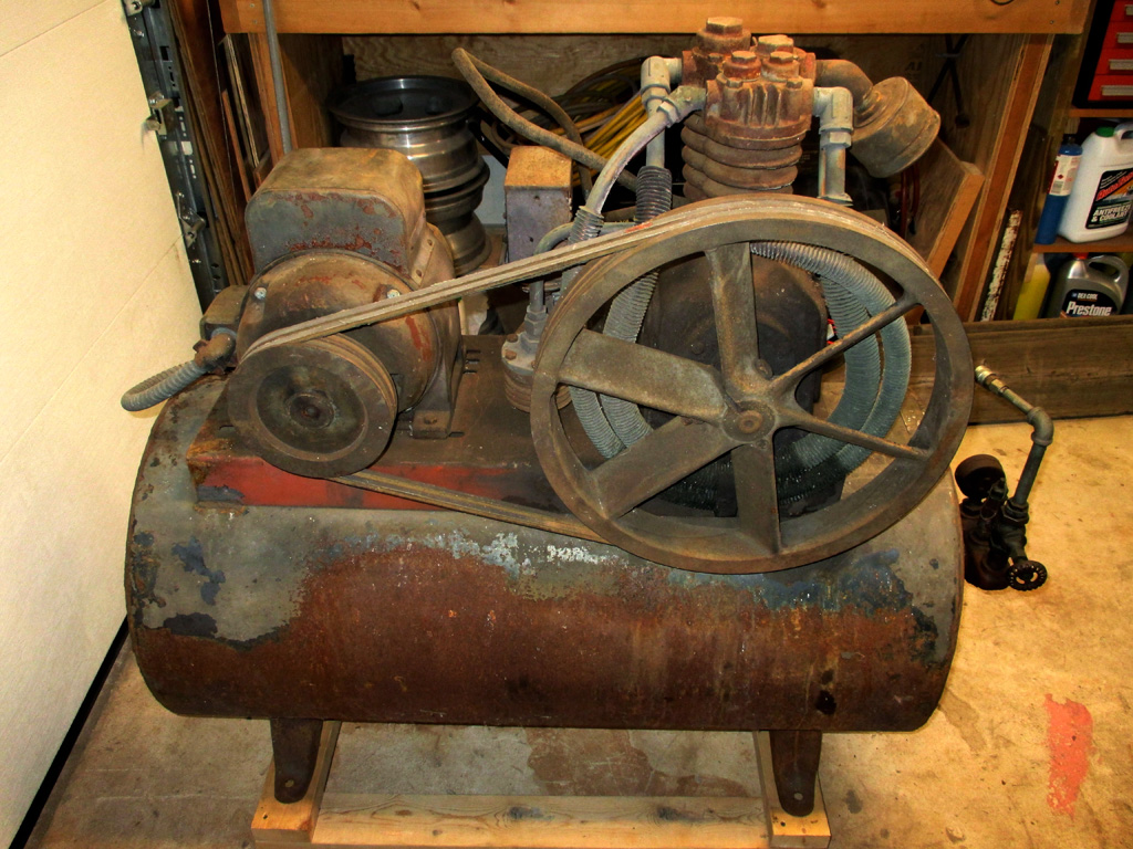
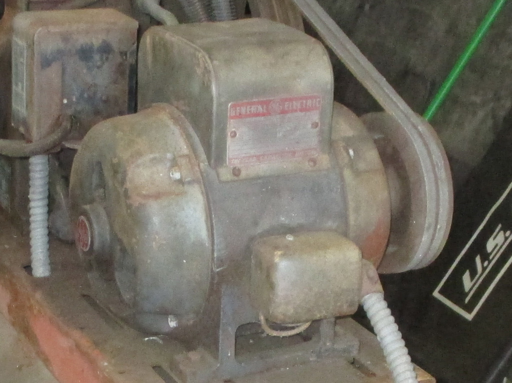
Growing up, my Uncle Ray had a big-ass compressor in his barn. He used all kinds of air tools with it, so my plan was to look for a compressor like I remembered from being a kid. Once again I turned to Craig's list and found what I was looking for. Made back when things were made in America, made with pride and made to last!
I decided the best way to get this running would be to service the rings and the valves. My plan has one fatal flaw. I have to find someplace to purchase parts for a 60 year old compressor! The parts guy at first place said no parts were available, but they'd be more than willing to sell me an industrial air compressor. Funny guy.
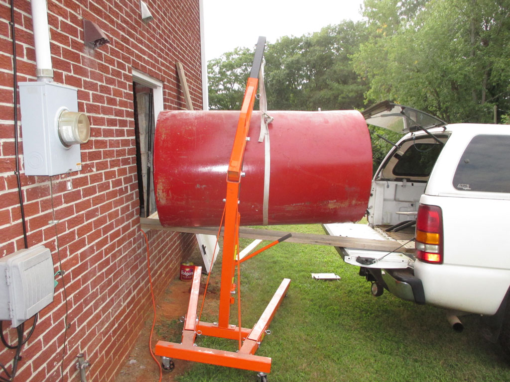
This thing weighs a ton! The seller and I used several poles (about 4-5" diameter) and an aluminum ramp to roll it into the bed of my pickup - Egyptian style! When I got home I unfolded my engine hoist, strapped two ratcheting tie downs around it to lift it so I could drive my truck out from under it and lower it to the basement floor.
This baby runs on 220! The electric motor is so heavy I have to be extra careful lifting it. A two-stage pump that loafs along at 750-800 rpm and should be a lot less noisy than the "screamer". This... this is what I'm talking about MADE IN USA! I wasn't about to pay $800-$1000 for a Chinese made POS made with recycled tin cans and slap-in-the-face tolerances.
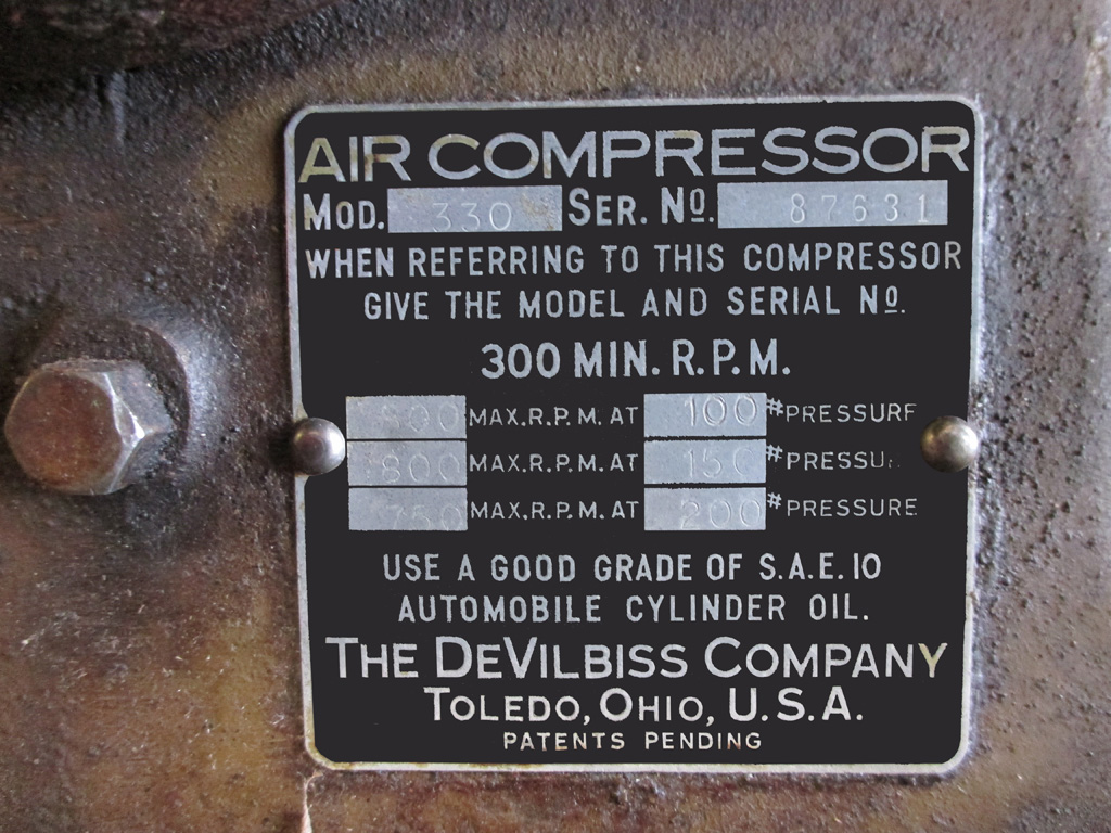
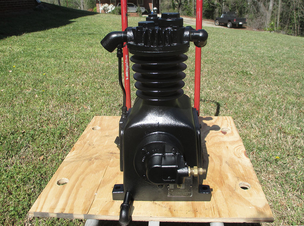
PUMP SPECS
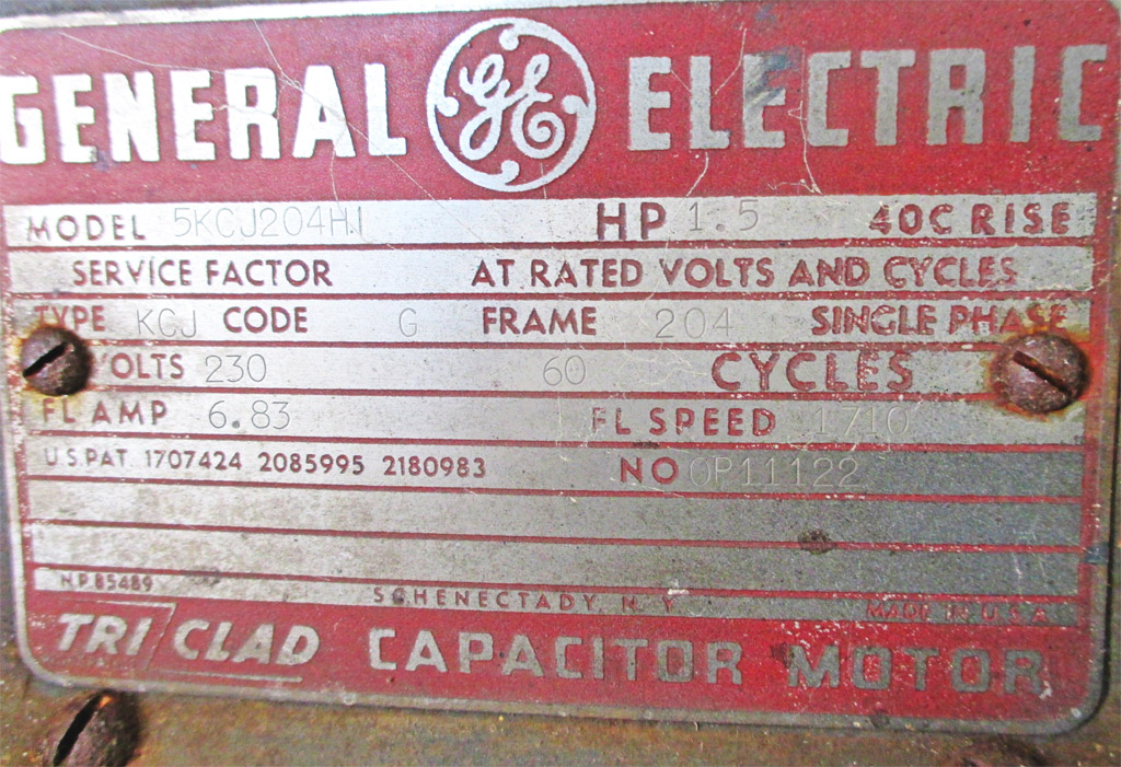
GE MOTOR
Built with stout cast iron, steel, copper and brass in a unit made when quality was valued and the cheapest possible construction wasn't the primary goal. At the end of the day will I come in any cheaper? Time will tell I guess. I'd really love to come in substantially under current retail, but even if I don't, I will end up with (I sincerely hope), a much higher quality machine by taking this approach.
Take a gander at this baby. It is HEAVY! No, make that HEAVY! Heavy enough that thoughts of what could happen should I be foolish enough to drop this monster are truly sobering. In actuality, it probably weighs in at around 100 or so, but I'm not about to crush our bathroom scale trying to weigh it. Damn.
Unbolting and removing the electric motor (keep your back straight, lift with your legs) gave me a real workout. Once I set this little gem aside, the twin V-Belts (a matched set, so I'm thinking: $$$), fell right off and I set them aside for safe keeping. A peek inside revealed that the capacitors had been replaced at some point in this machine's history. I've found a company that can check it out and let me know whether or not its salvageable. Until I can refurbish the pump, this is a moot point.
The big decision will be repair or replace? I've seen replacement electric motors in several stores. Not only are they expensive, you have no idea (but I could probably guess) where they're made. We tried starting the motor with two 110 volt cords (from two differently phased circuits), but the GFCI circuit on one of them tripped instantly at the load. At least we tried.
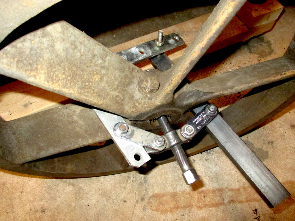
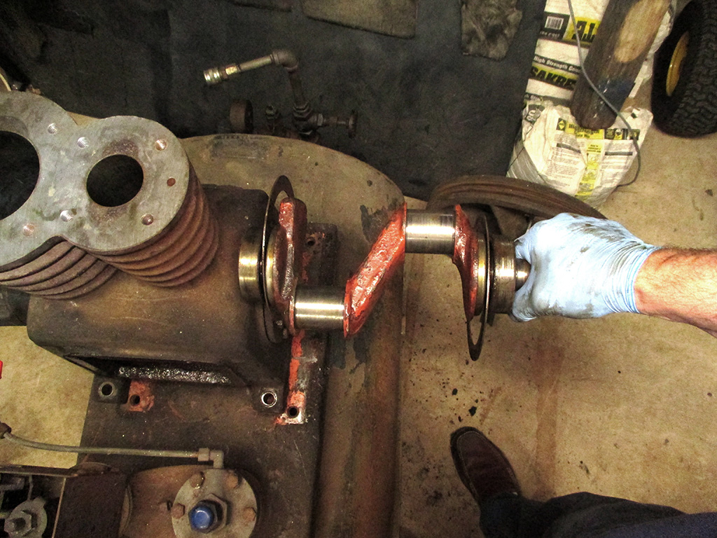
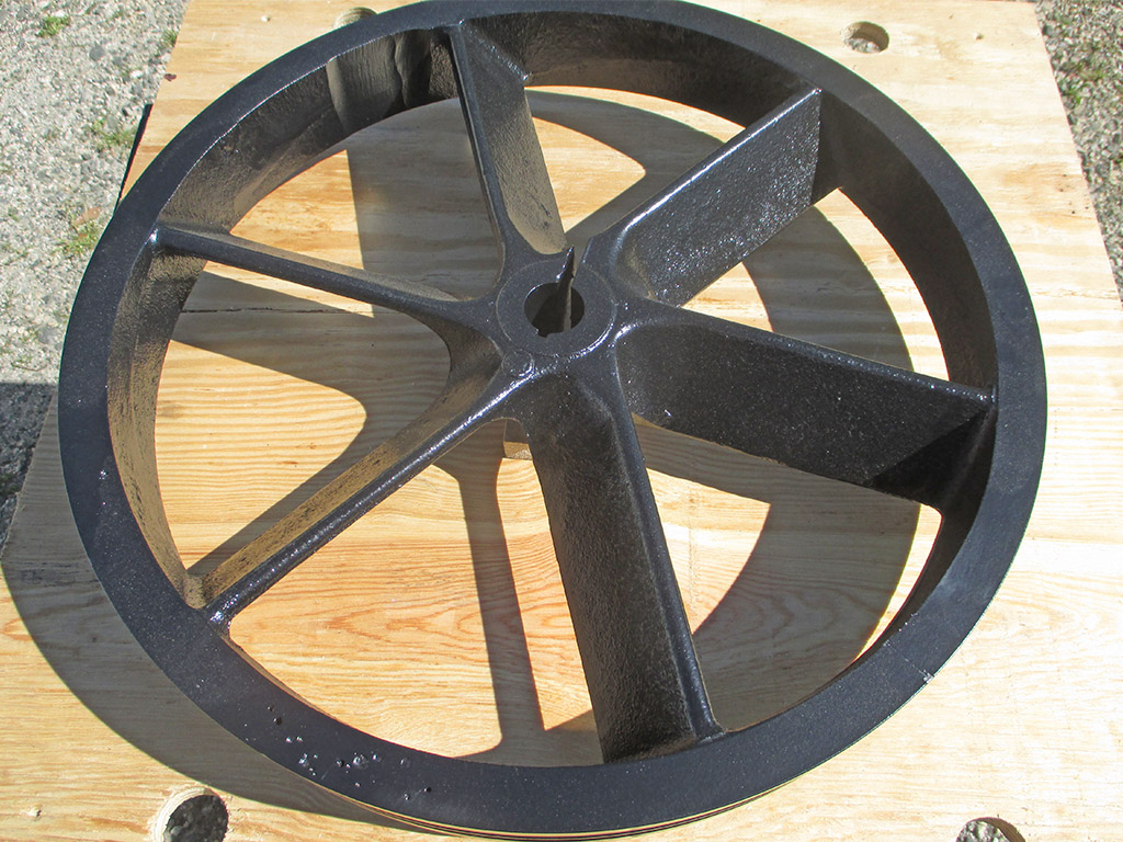
The next challenge came when I went to remove the flywheel/pulley assembly. None of the pullers I have even came close to being wide enough and deep enough to grab the pulley properly. So... I got creative. Step one, soak the crank and pulley with PB blaster. I dug through what I had on hand and bolted a 1/4 curved strap from a garage door opener and a section of 1" angle iron to the puller.
It may sound crazy, but now I could apply the force of the puller to the back of the pulley's hub and as I tightened down the puller on the end of the crank... it actually worked! Hooray for me. I had to be careful not to drop this baby on my toes either or I'd have learned the Irish Jig in about 2 seconds. Like everything else on this machine, it puts the HEAVY in Heavy duty.
Again, I used the PB Blaster (not knowing how whether or not the fittings might be frozen), and carefully set about breaking them loose. Turns out I was worrying needlessly (or the blaster worked really well), because they came apart just the way they should. Quite a few itty bitty spiders scurried about with the commotion I was creating, but a quick pass with my propane torch eliminated the infestation. I carefully set these aside, to be reinstalled at a later date.
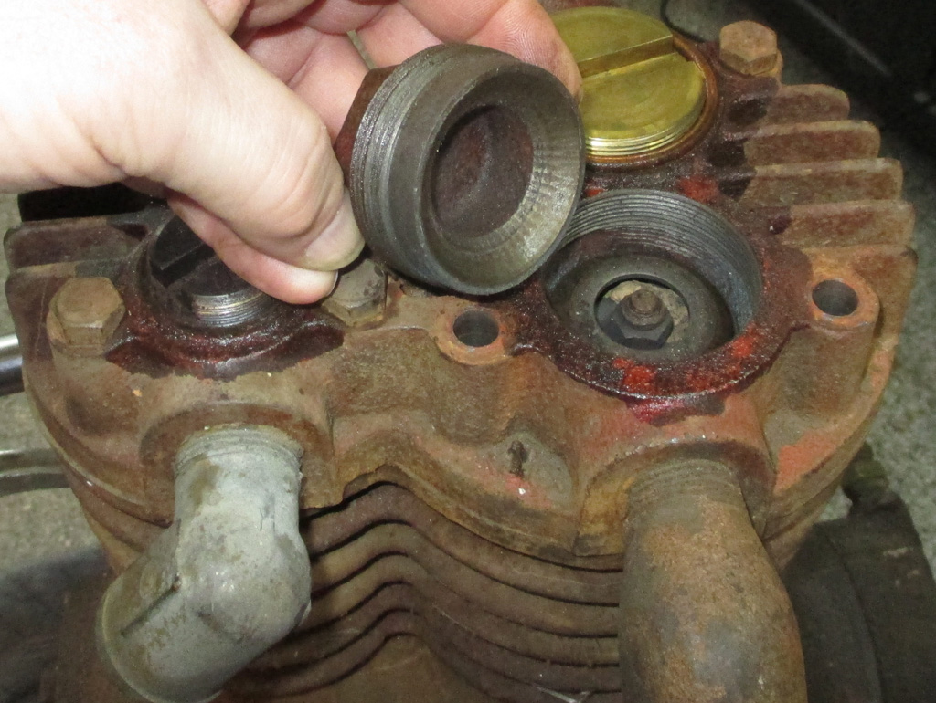
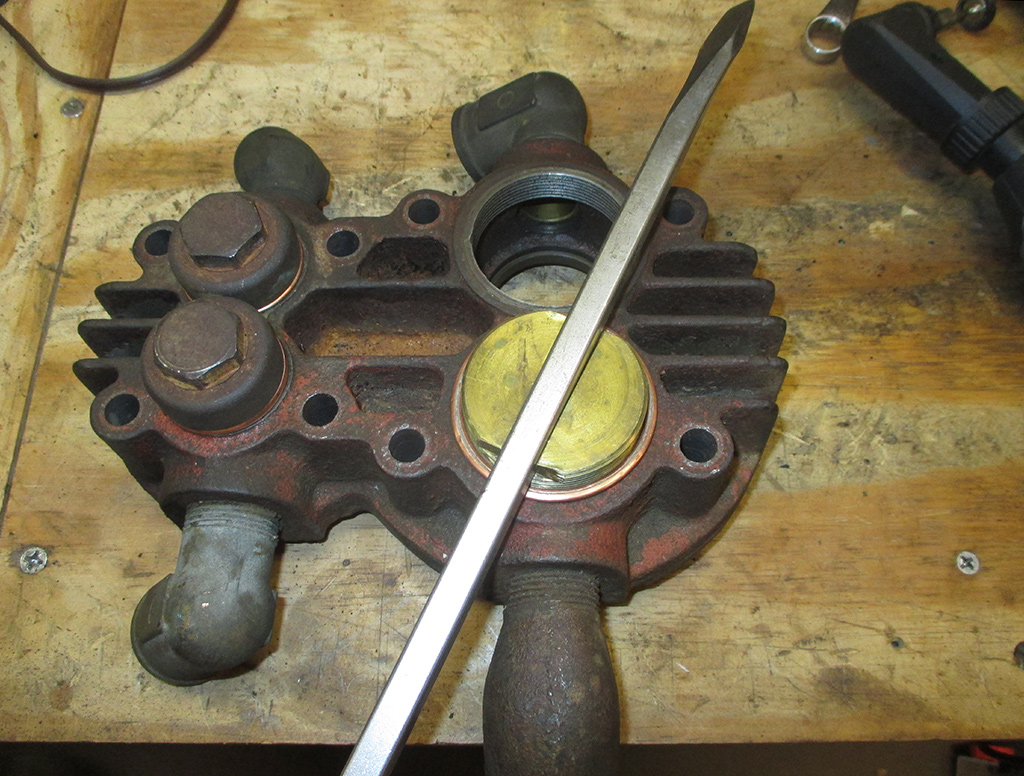
I removed some of the head bolts to gain access to the caps that cover the brass valve retainers. I did this off site so I used some Marvel Mystery Oil in place of the blaster. I think it helped, but the disassembly kept moving forward smoothly, as if the compressor had been housed indoors or (at the very least), in an outdoor shelter of some kind. I kept expecting to find that one fatal flaw (two or more parts fused together via corrosion), that would scuttle the whole project but incredibly, we were able to tear down the pump without incident.
To check out the valves, it was necessary to remove the cast iron caps to get to the brass valve caps (my word) which cover the intake and exhaust valves. The best way to describe them is steel cups with spring-loaded restrictors underneath. The movement of the pistons is enough to overcome the spring, then close as soon as the piston travels in the opposite direction. Similar to an internal combustion engine in my mind, but pulling in air (not air/fuel) then filling the tank with the compressed air, not sending it out a tailpipe. My two stage unit has a large piston to feed the small piston which in turn fills the tank.
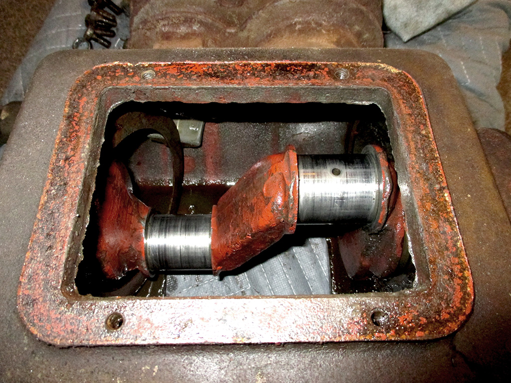
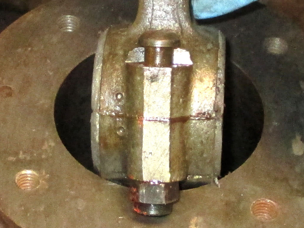
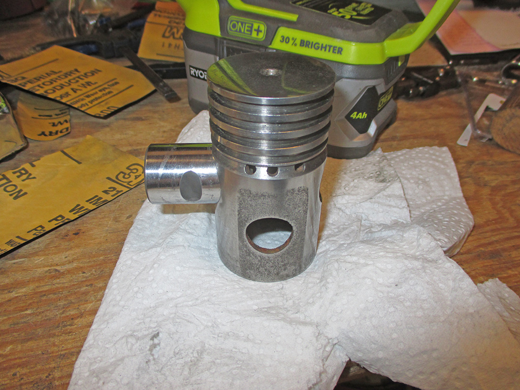
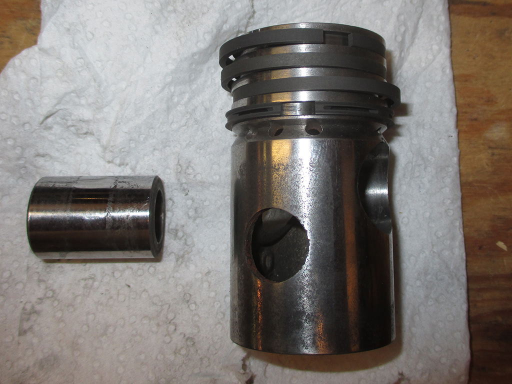
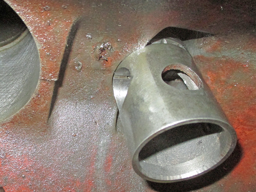
With the topside broken down, it was time to pull the crank. But first you have to take off the side plates so you can remove the connecting rod bolts and caps so you can pull the piston. We soon discovered that this approach would only work for the large piston, because both pistons had the same size connecting rods but different sized bores. The 4" piston came out the top, while the 2 inch one had to go down into the crankcase for removal. I have no idea how we're going to put the small piston back in its bore at this point. Once we cleared that hurdle, we turned and pulled the crankshaft out through the end plate.
More of a reference shot than anything else, lest I forget where everything goes between disassembly, cleaning, painting and reassembly. Whew! What a job. Times like this I really do think I must have rocks in my head or some other disability to tackle such a project, but my automotive refinishing projects hinge on me getting enough air to do the job. I have to keep telling myself that it will all be worth it in the end to have the volume of air I need for my little hobby.
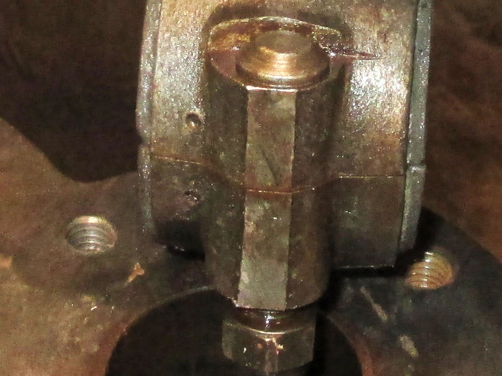
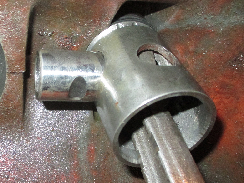
If you're lucky, the connecting rods will have some kind of indexing mark so you can put them back the exact way they came out. In this particular instance, two adjacent dimples were stamped in the side of the con-rod as seen here. Because this has been running for years in the same configuration, you have to make sure it goes back together the same way. There are kits with small dies to create such marks if you happen to pull apart an engine that doesn't have any of its own.
Yeah... that's definitely not going to fit. I think the way this works is the large piston feeds the smaller piston and the small piston is what fills the tank. I think. At this point, what I know about air compressors (other than just using them), would fill a thimble... with room left over. Ah, but I am nonetheless learning as I go, which is difficult with nothing else to guide me other than an exploded diagram and parts list. I am on the hunt for some sort of torque settings so when the block comes back from the machine shop, which I'll need to properly reassemble this.
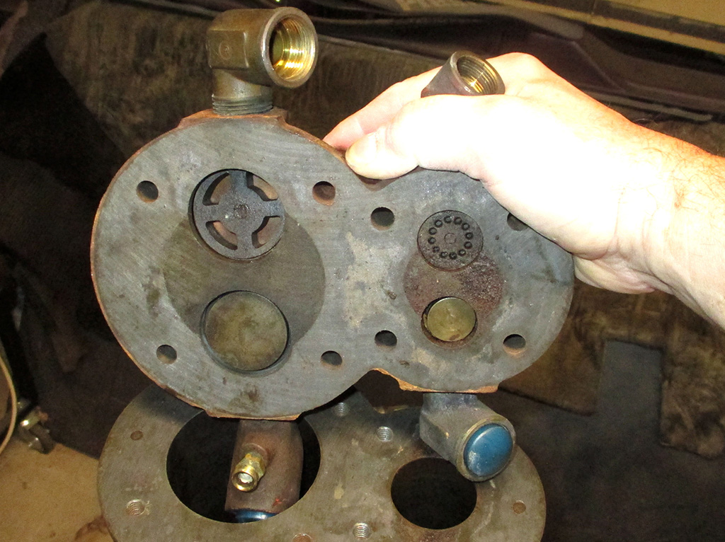
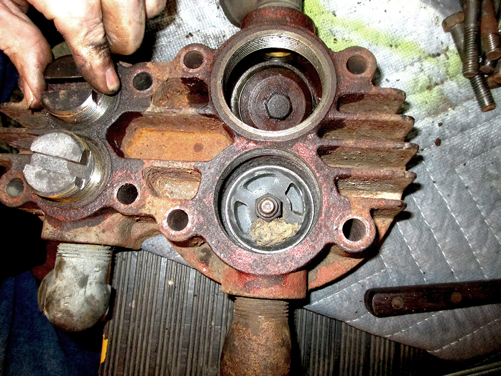
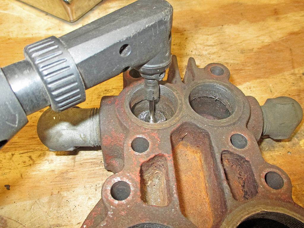
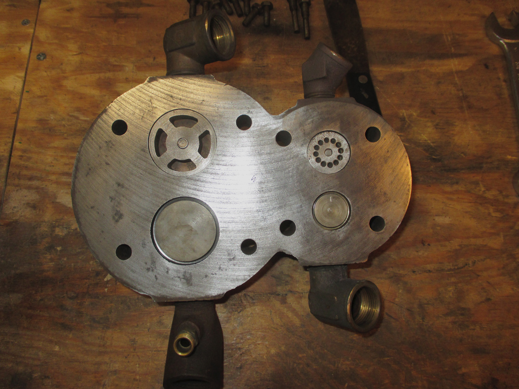
Here's a shot of the business side of the valves in the head. The primary intake (where the air filter was) is in the large bore in this shot. This leads me to believe that both intake sides have the brass valves in this shot. Then the air goes out through the other openings which obviously seal shut from the other side. At least that's my current speculation on how the whole thing works. Once I can find out some information on this I'll revise my theory as needed.
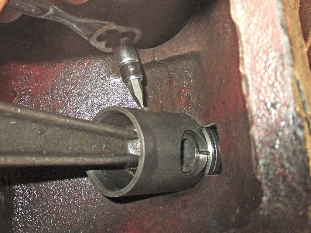
Since the pressure control switch is mounted to this... uh... apparatus, I'm guessing this is some sort of pressure control assembly. With no user guide or service manual to go by, I'm making an educated guess on this. Big time. It's pretty cool looking, with a science-fiction, art deco kind of a vibe going on.
PRESSURE CONTROL
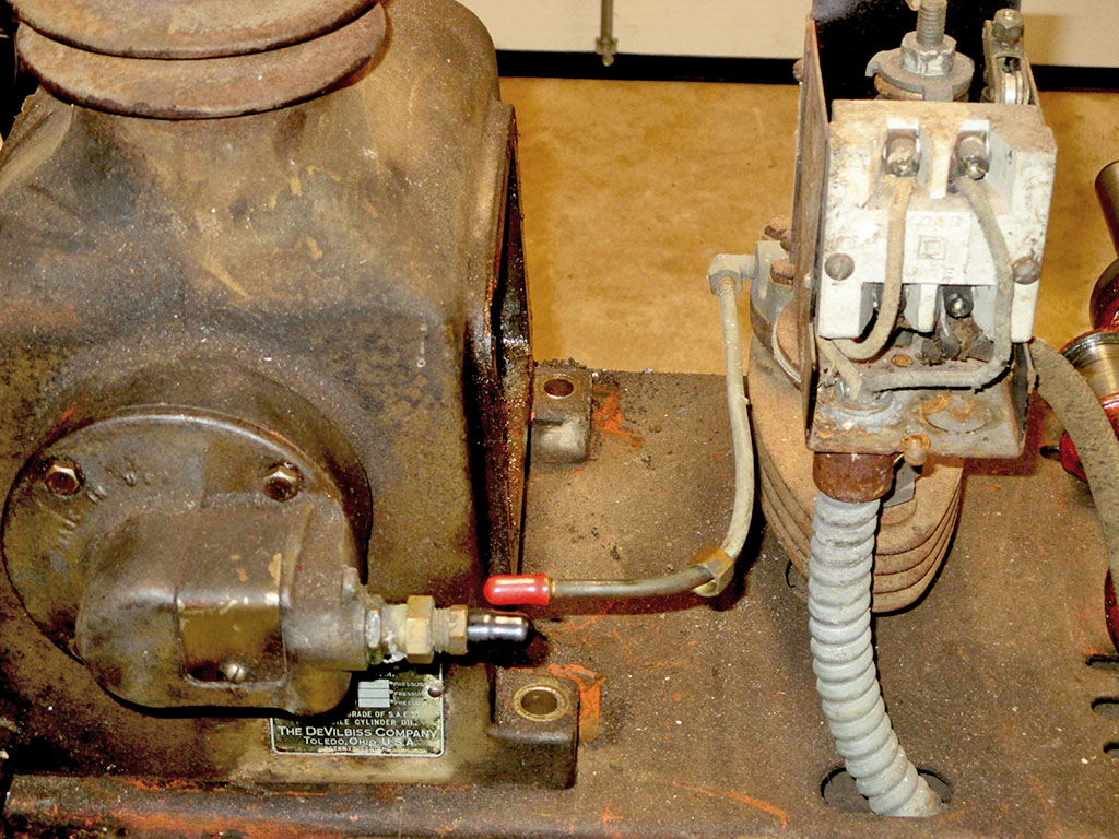
TUBING CONNECTION
The big temptation (for me anyway), is to sand, paint and maybe polish the aluminum on this vs. simply rebuilding it mechanically to get it up and running in as timely a fashion as possible. In the end I'll probably wire-wheel it and fog it black. I cap off every orifice since the south is blessed cursed with tiny flying insects that love to fill holes of a certain size with mud. I loathe the accursed things, hence my obsessive capping off of all such orifices.
After the teardown, the next step was to get the block honed so the new rings can seat properly. Following a word-of-mouth recommendation I settled on this place to press the bearings off the crankshaft (and clean up the keyway) in addition to freshening the block. They're supposed to do good work, so on March 6th, I dropped everything off and began to play the waiting game. At $75.00 an hour, I hope they work quickly.
I tried picking up my block on April 3rd, but the shop was closed tight as a drum for Good Friday. I showed up a week later to pick it up only to find out they had called me on the 20th of March to tell me it was ready. Not sure where the voicemail went, but for $125 bucks I got a freshly honed block (large bore only) and they'd pressed the old bearings off the crankshaft and cleaned up the keyway.

The machine shop foreman told me when I dropped off my block, that I'd have to use a brake cylinder hone for the small bore... he didn't have a stone that small. Uh... okay?
A Saturday morning trip to my local Midway Auto Parts store netted me one for $15 and change. I downloaded a manual for a similar 2 stage compressor and they mentioned honing the cylinder bore for 20-30 minutes. I think I can handle that. The BIG question is... what ring gap is required for new piston rings?
I've spent hours trolling the internet looking for this critical specification. My only other recourse is to call a company called Phillips Air Compresor in Chicago. Legend has it (according to a post on the practical machinist website) that a bunch of old timers work there who may be able to help. If they can't help...
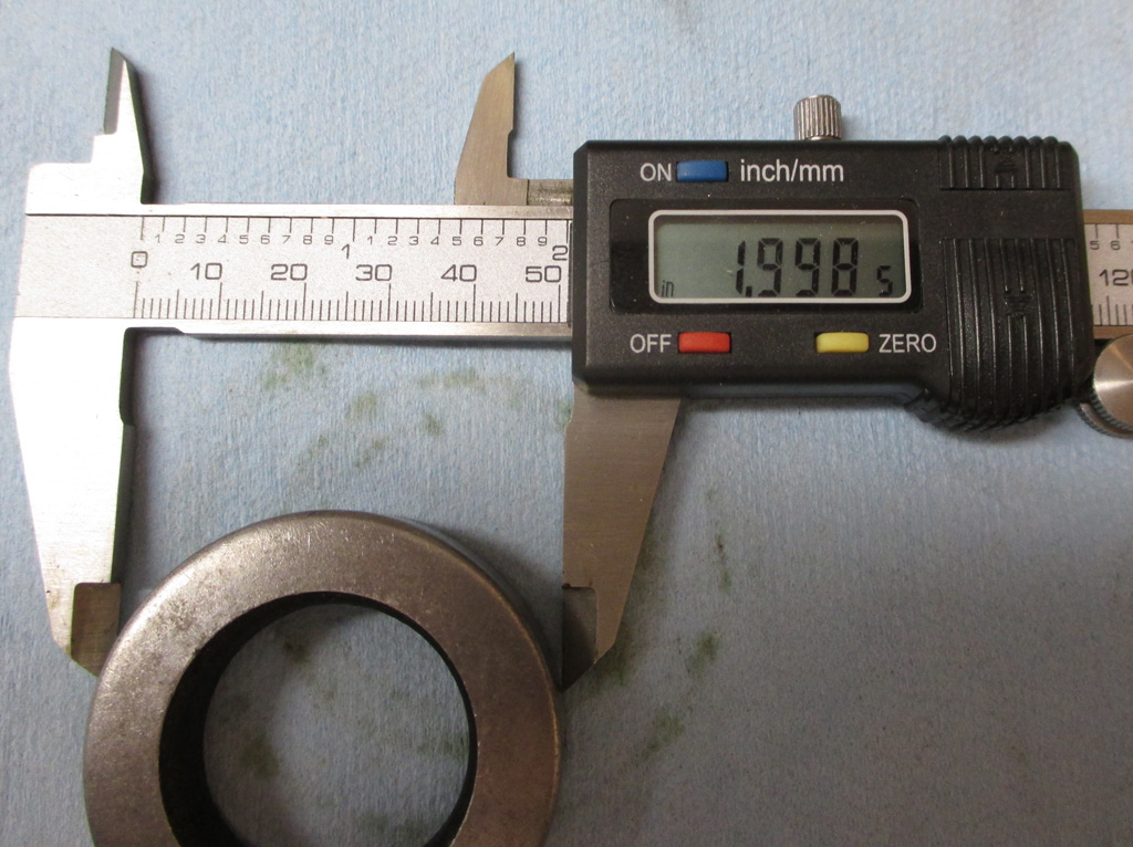
With the whole "ring job" on the back burner, I still have other issues to occupy my time. When we disassembled the pump, one of the bearings felt a little rough. Companies like Grainger or McMaster Carr carry all sorts of bearings, you just need the dimensions of the originals.
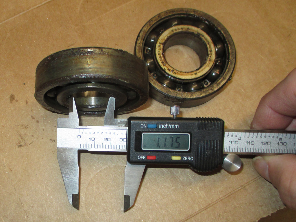
INSIDE (1 & 1/8th or 1 & 3/16ths)
OUTSIDE (2 & 7/8ths or 2 & 13/16ths)
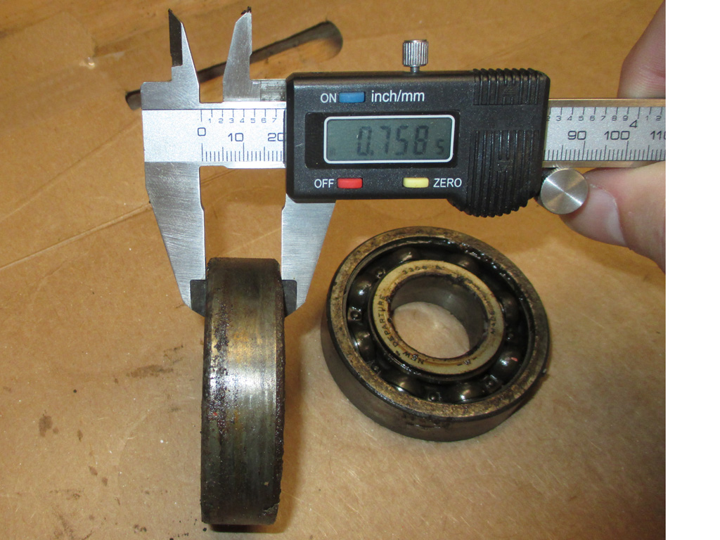
THICKNESS 3/4 inch
So, little-by-little, work continues to move along. I have other things I can do (other than shopping for new ball bearings), including removing the surface rust from the tank in preparation for some paint.
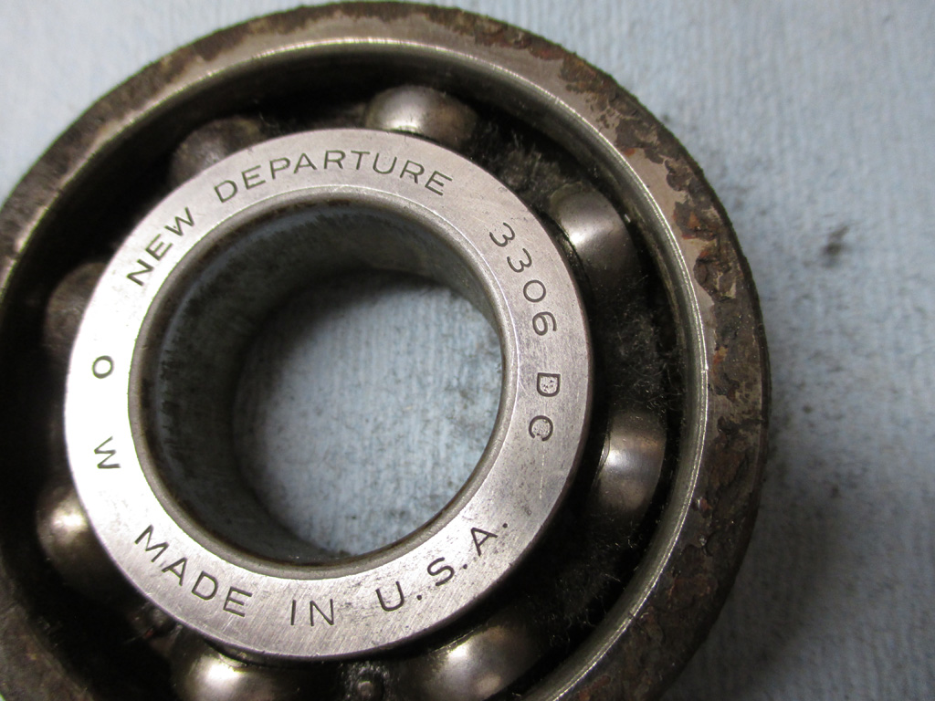
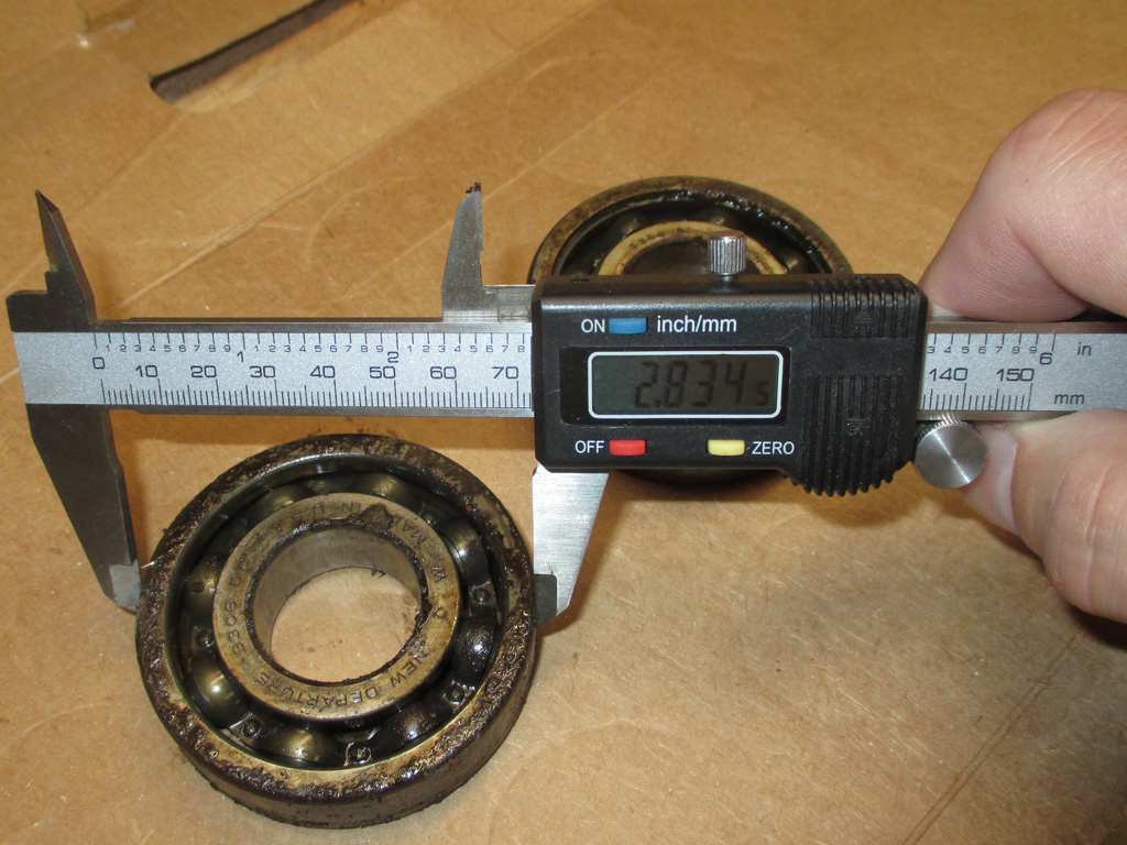
So... here we are. Your basic New Departure 3306 radial ball bearing assembly. I've purchased many of these types of bearings over the years (mainly for my garden tractors), so this should be fairly straightforward. Uh... nope.
I tried McMaster Carr, Grainger & Atlanta Air Compressor. Nothing. Now what? I found a Timken regional sales office in Charlotte, so it may be time for a road trip. But first... I'll troll the bay of E just in case I might get lucky.
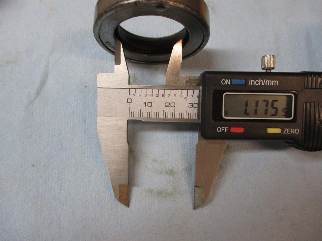
In addition to bearings, I'm going to need a new oil seal. This also had a handy part number on it. Unfortunately, there is no manufacturer name. Is it a DeVilbiss number or some other part number? This is the conundrum I'm facing as I break out the digital caliper once again. This is also a double-sided spring seal, with steel on both sides instead of being open on the inside.
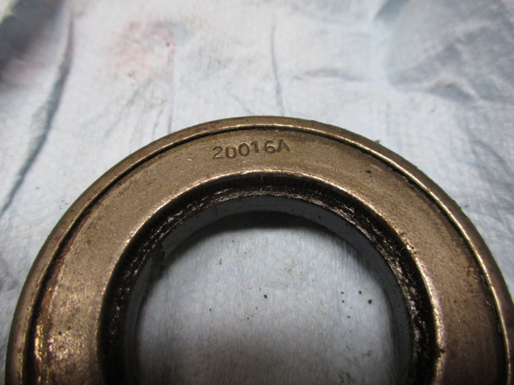
Part Number
Inside
Outside
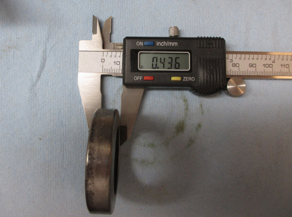
Thickness
The outside measurement was 1.998in. You really cannot get much closer to 2" without actually being 2" can you? I've never been much for dissecting the measurements on a ruler. The thickness came out to 3/8ths of an inch on my trusty ruler. I've done what I can in the name of accuracy, now to see what I can find out there.
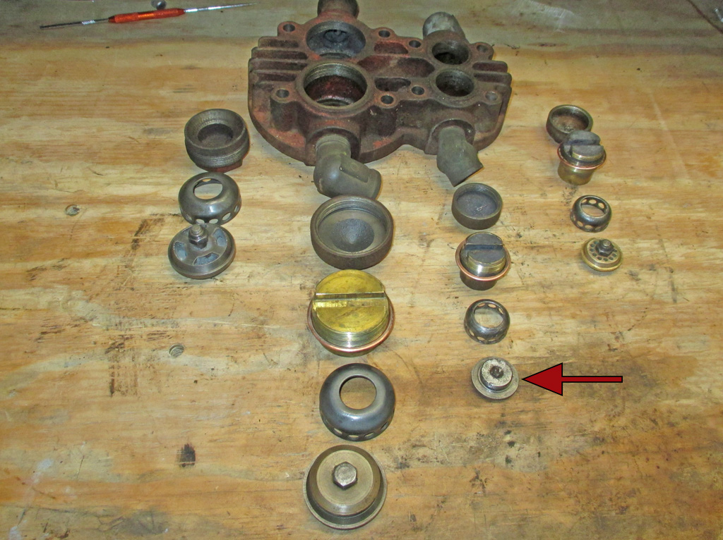
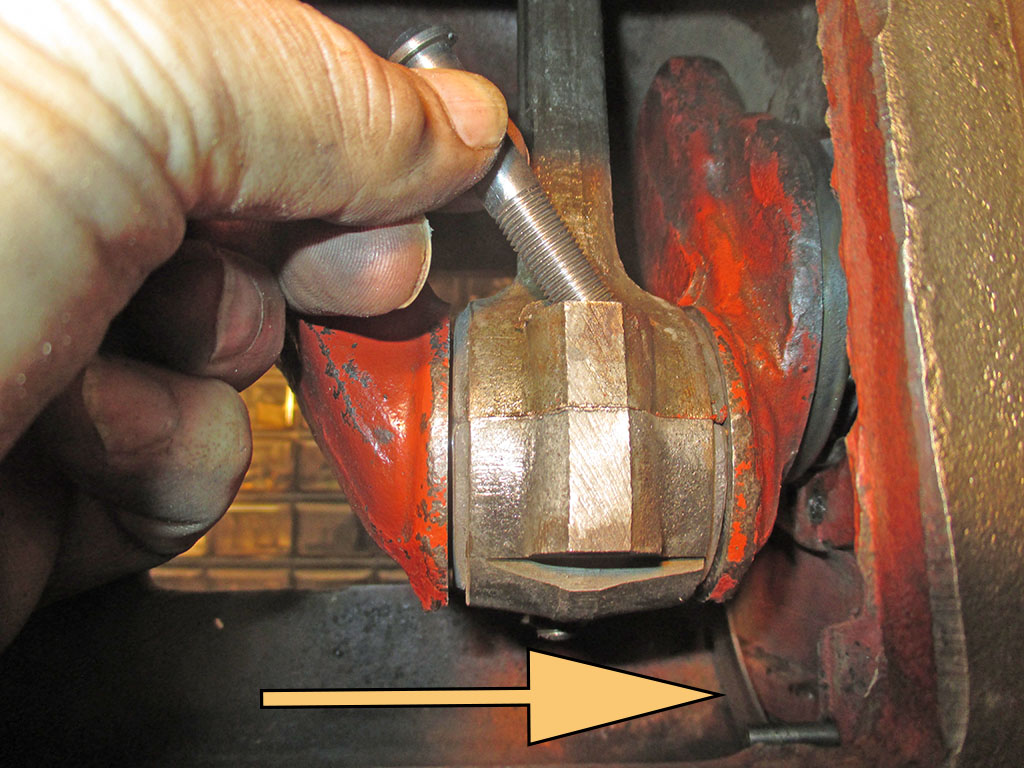
With the bearings finally located (eBay - of course) and on their way from California, it was time to get the head and valves back in shape. One by one, I pulled all the components out (being super careful to keep them in order), and did my best to clean everything up again. One of the smaller assemblies (arrow) had some rust issues but cleaned up pretty well. All the remaining assemblies cleaned up just fine.
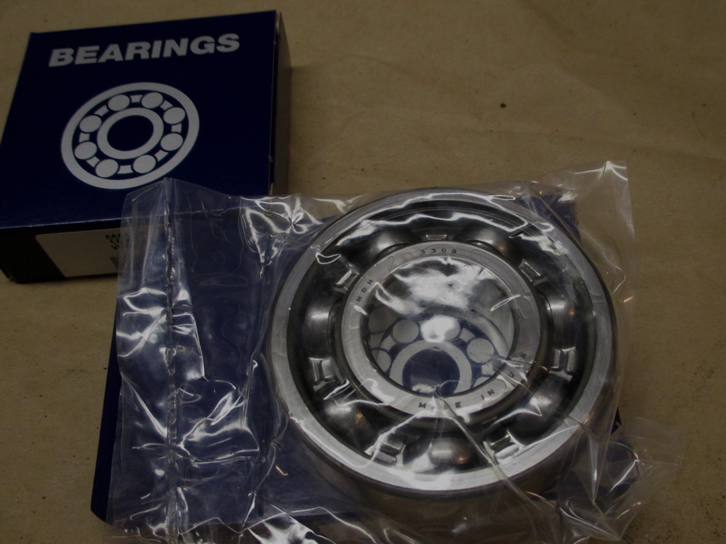
I ordered these from a company called (quite appropriately I might add), Locate Ball Bearings. They had an auction for the same New Departure 3306 radial ball bearing assembly I was looking for.
I emailed the seller a question about dimensions and was told to call for details. I called, asked for measurements, they said they would call me back after measuring one. They actually called me back and the dimensions matched! So now I'm one step closer to reassembling my pump.
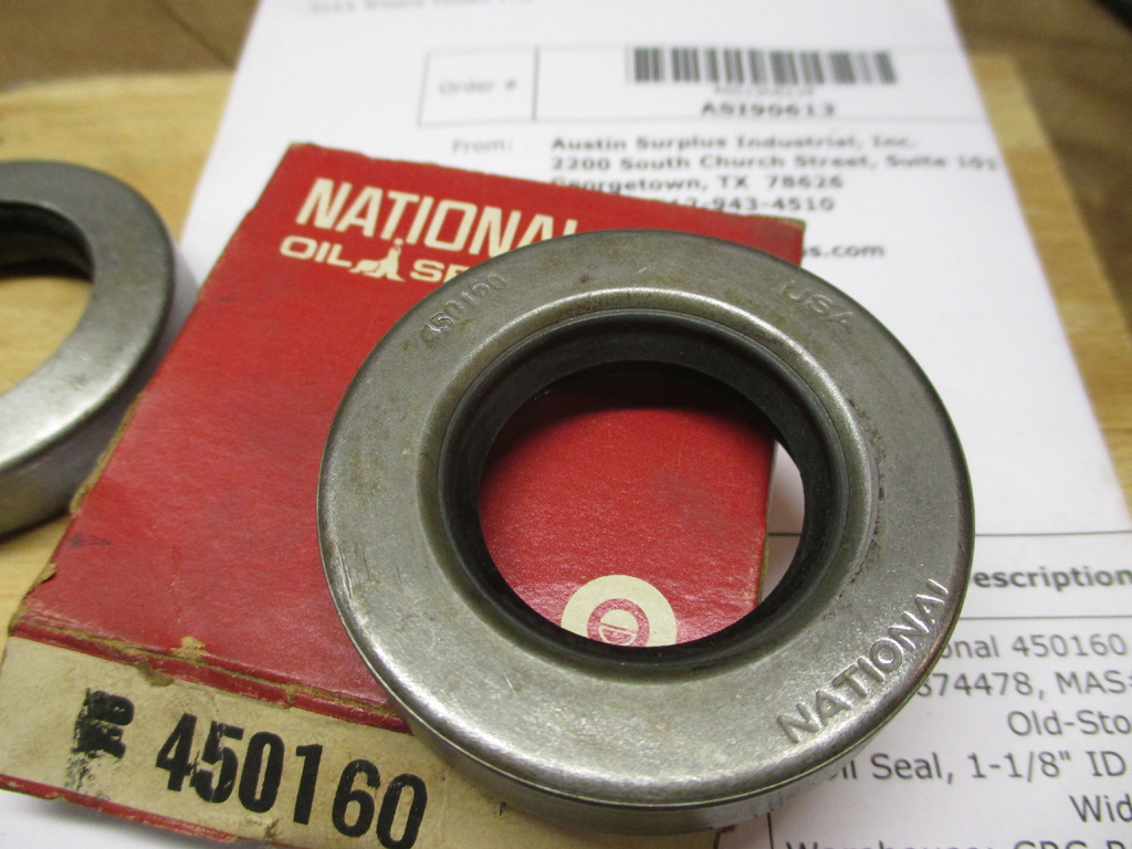
I played detective and located (eBay - again!) the oil seal I needed, this time coming from Texas. One by one, I'm pulling together all the parts necessary to put the pump back together. This is N.O.S. (New Old Stock) new parts sitting on a shelf waiting to be needed.
Next on my to do list is tracking down a set of matched v-belts, since the old ones have had it. Then the biggie... getting the electric motor checked out. Hopefully it can be pressed back into service.
As the machine-shop foreman recommended, since they didn't have a hone this small, (really... you're a freaking machine shop aren't you?) I purchased a brake cylinder hone so I could do that part myself. With the oil seal on it's way, I figured I better quit fooling around and finish the prep work on the block.
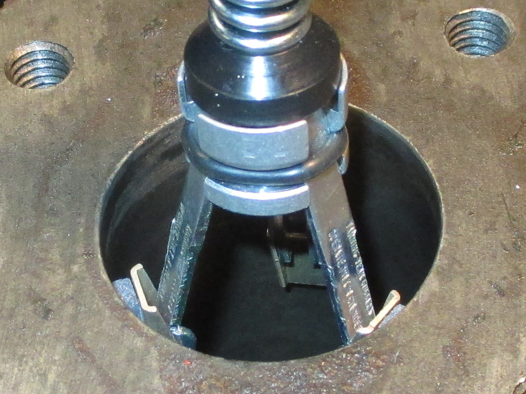
STARTING OUT
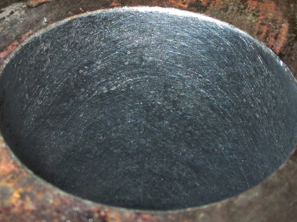
WE'RE THERE
You don't realize how tired you arm can get until you've honed a cylinder like this one for 30 solid minutes. My full-size drill press is on the fritz and my small one doesn't have the travel needed to reach the bottom of the bore, I had only one choice left. I grabbed my trusty drill, chucked up the hone and had at it... manually!
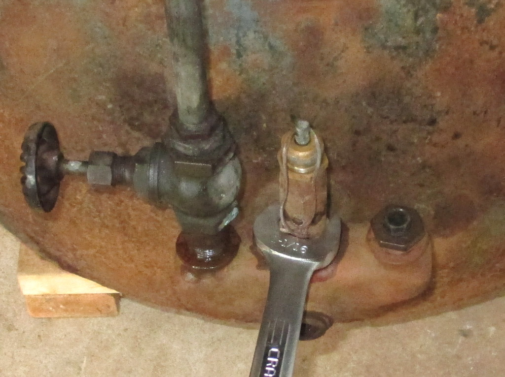
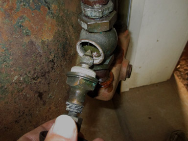
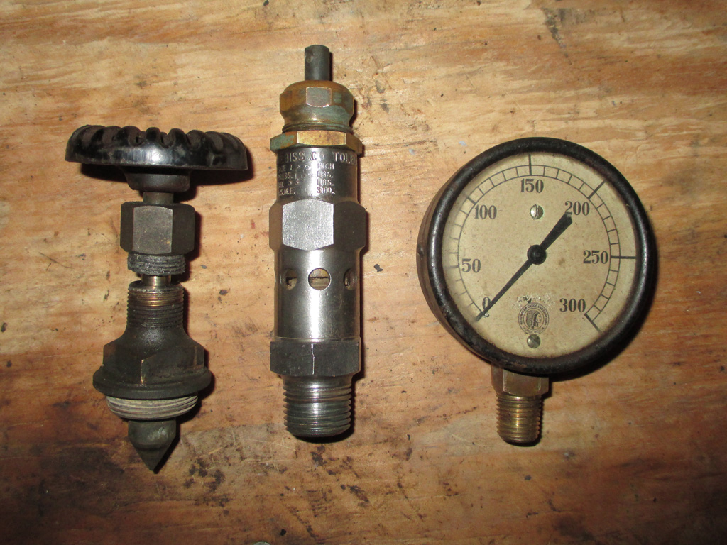
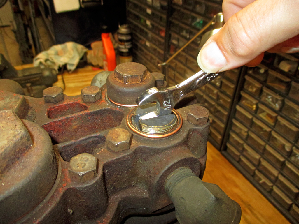
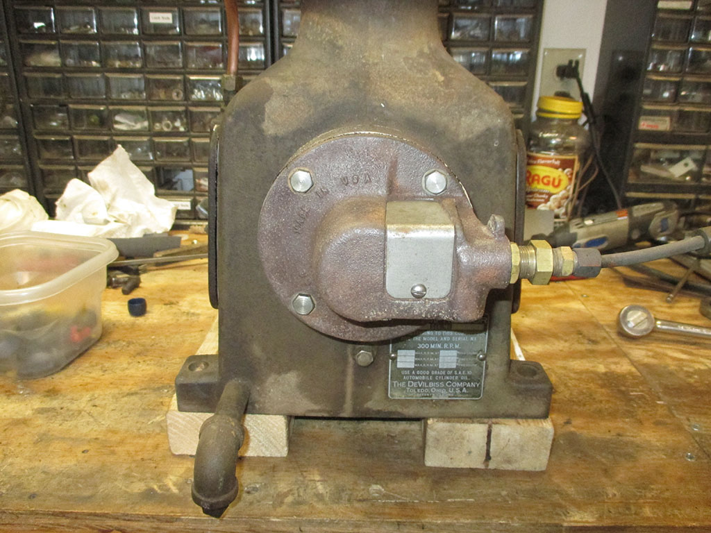
The pressure gauge was pretty easy to remove with an ordinary 1/2 inch wrench. I was somewhat surprised to hear a hiss of air as I removed the gauge. My plan is to re-use as much "old technology" as possible including the air pressure gauge. I do not want to pollute my vintage technology with anything manufactured outside the United States of America.
The over-pressure pop-off valve was next on the list. I needed a length of pipe to use as a leverage bar to loosen the valve. I had to wedge the tank between the garage door opening and my tractor in order to be able to unscrew these pieces. I originally put the tank on wheels so I could move it around my tiny shop, but I now I had to get creative to hold the damned thing still.
Before I could unscrew the valve assembly, I had to take the valve itself apart. I originally thought the packing was a section of threaded stock used as a spacer. Closer inspection revealed I was actually looking at the packing material for the valve.
STEP ONE
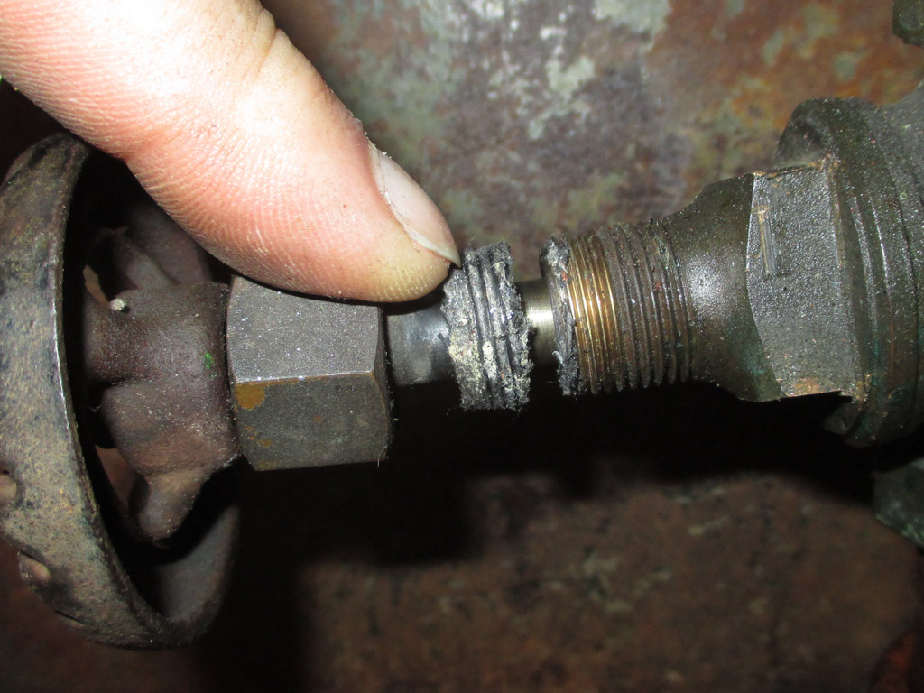
STEP TWO
Realizing my mistake, I put the whole valve, packing assembly back together the same way it came apart. Then I spent some time cleaning (wire wheel in drill and brake cleaner w/rag) all the other parts installed on this end of the machine.
Vintage parts are essential when you're building a Steam Punk style air compressor. Actually though... if you stop and think about it for a moment, this is the real deal. I tend to wax nostalgic when I'm refurbishing vintage technology. The biggest problem? Locating the parts needed in a world that has definitely moved on. I'm an anachronism. I am a rebuilder in a "disposable lighter" society.
Whenever I work with pistons and rings I tend to break a sweat. Always lurking in the shadows is the spectre of broken rings. It doesn't help that the very act of installing new rings is risky due to the fact that you have to spread the rings to get them onto the piston and into their respective slot. Doesn't help that the oiler ring has slots cut into it making it even more fragile. Nuts!
RINGS INSTALLED
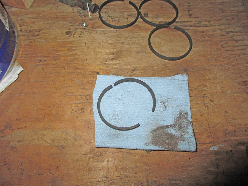
BROKEN RING
So on the pump-rebuild front, the ring-job netted mixed results. The new rings are on the large piston, which went together just like an automobile piston. The small piston oiler ring fought us and snapped. So while I wait for another set to be shipped I busied myself with other things.
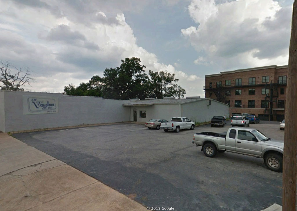
If any readers decide to follow in my footsteps, there are a few things you will need. Make sure you brush up on your "Google-Foo" because you're going to be on the 'net for a while. Next, be prepared to become a detective. Just like Mike Hammer or Sam Spade, you'll do research and follow down leads. I went to a shop that (theoretically at least) specialized in air compressors and drive belts. No dice.
But... just like a rumpled gumshoe tracking down a lead, this place told me of another place several miles away that DID CARRY the matched drive belts I was looking for. I hopped back in my truck and went to this new shop. I showed the guy behind the counter what I needed and in a few minutes had two new Gates belts in my hand. Didn't break the bank either, coming in under $20 bucks.
As I paid my bill I asked if he knew of a shop in town that could check out my electric motor. He referred me to a shop in town that checked out and repaired electric motors. Naturally he gave me a sales pitch if I needed a new motor. I didn't mind, I now had another lead to follow up on.
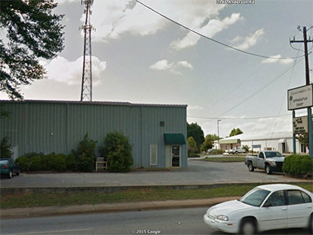
Enter Ye Olde Aparatus Shop. Okay, I added the "Ye Olde", but could there be a shop name any more vague than Aparatus Shop? My dictionary defines Aparatus as: a tool or piece of equipment used for specific purposes. After spending some time inside, I realized that if they'd put "Electric Motor Sales and Service" on their sign the shop would be much busier that it was.
As I stepped through the door, I also stepped back in time. The Coke machine I passed was every bit as vintage as the two guys working there. One guy was in his 80's, the other in his 70's one of whom had been working there since they were 17 years old! The shop was full of electric motors in various states of repair. They hooked my motor up to an ancient workbench with a foot pedal and tapped the pedal.
Amazingly, my motor cranked right up! I was amazed. They put oil in the two spring-capped access ports and tested it again. It has some play in the shaft, but they said bushings stopped being available 30 years ago. A replacement would be either $380 (for a 3hp) or $480 for a 5hp replacement motor. Then I'd have to fab up a mount to match the mount on my tank. I'm going with the original and see how I make out.
Regardless of all the other components (like the pump and electric motor), vying for my attention, there's a pink elephant in the room that's been ignored up to this point. I guess I really can't put it off any longer... there's one key component I really need to get moving on.
It's... the TANK! As I've tinkered with this, there's been this nagging thought at the back of my mind that maybe (even though I'm up-sizing my equipment), just maybe... it wasn't quite large enough to meet my needs either. A truly sobering (not to mention horrifying after all this effort) thought if ever there was one.
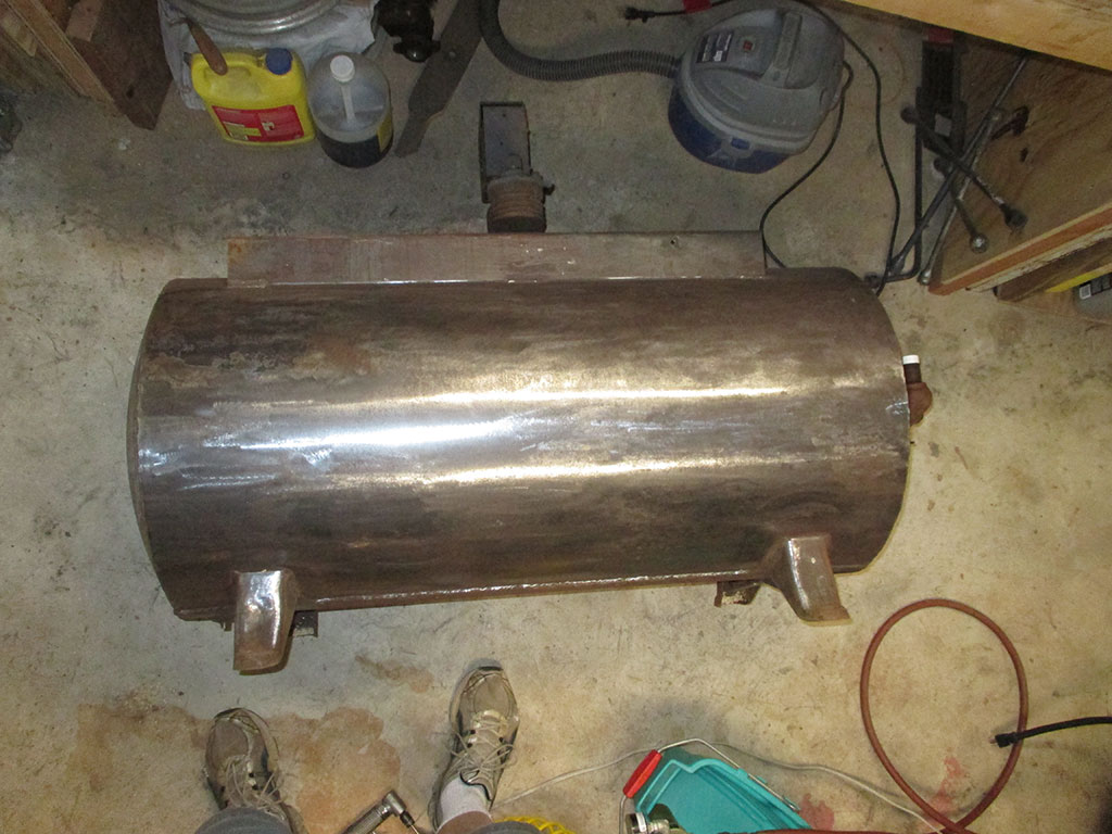
Then I started sanding it. I started with one of those poly-web/abrasive paint removing disks. It worked, but it was taking forever. It took me four hours (in our nice, balmy SC heat and humidity) to get to this point. Oh yeah... she's plenty big alright.
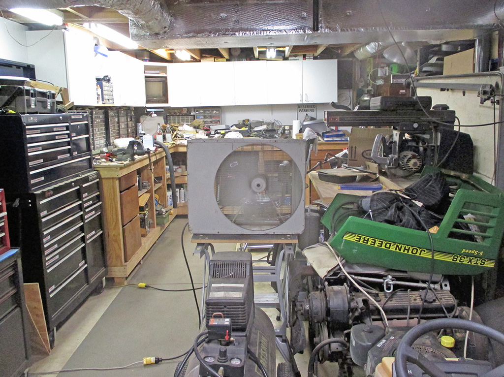
In order to combat the heat and humidity (to say nothing of the huge, brown cloud of rust dust I was creating), the situation demanded a serious solution. Enter my BIG ASS fan. I bought this at a flea market shortly after relocating to the South. For $20 I had a unit that would move some serious air. A word to the wise... never take a 40+ year old appliance and blindly plug it in to see if it works. I plugged it in, there was a loud POP, a flash of light (I immediately jerked the plug back out) and the shop went dark.
After re-setting the circuit breaker (and pondering the freshly melted/scorched electrical outlet) I determined that the original 50 lb. motor must've had a dead short. Stupid. I replaced it with a lighter unit, taking care to use the same size pulley as the original motor to keep the pulley ratio right. I stored the two sliding panels that came with it (to install it in a window no less) so I could have a portable wind machine.
Here I've positioned it to blow the cloud of dust I'm creating with my sanding out the garage door of my shop. Since the die grinder I'm using makes my Craftsman air compressor run almost constantly, I positioned the fan to blow over the compressor in an effort to help keep it cool. Not sure how well this works, but it sure can't hurt.
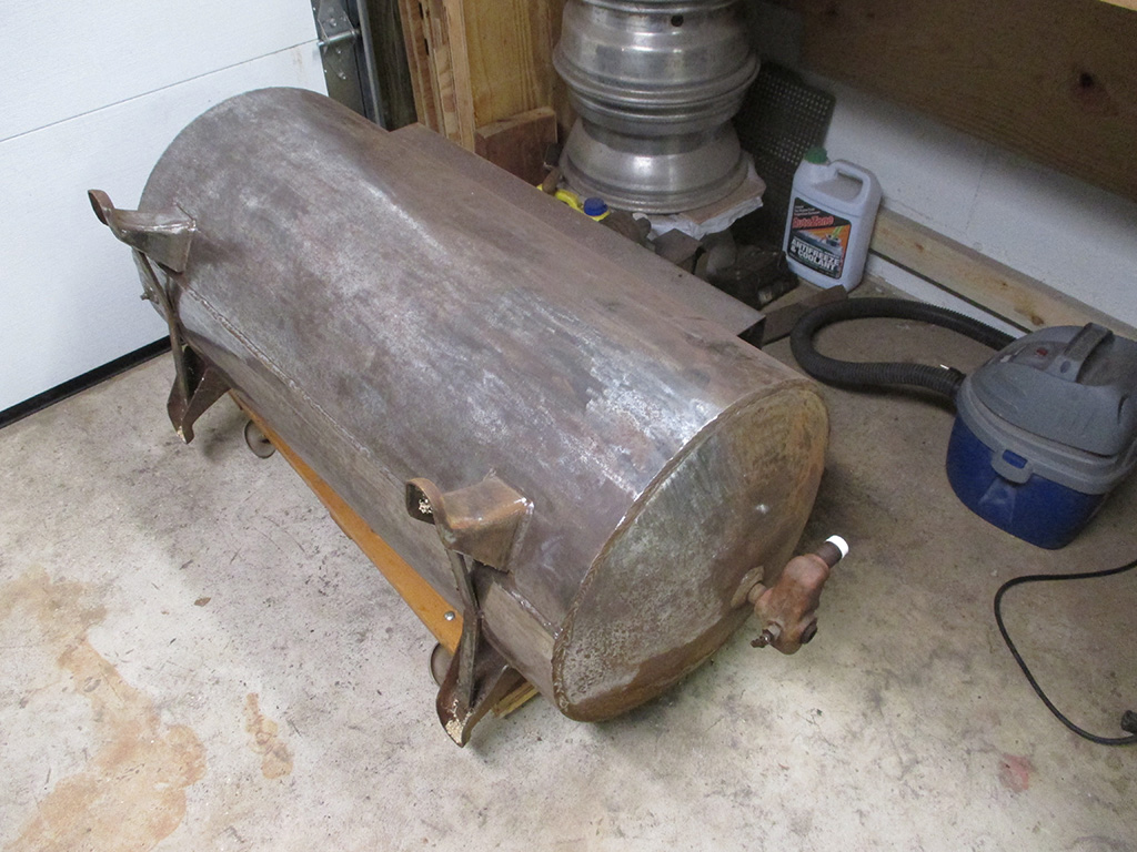
Day two saw me switch over to actual sandpaper, 100 grit to start. Still not making enough progress, so I switched to 40 grit on a 5" adhesive backed pad. Much better, but the 5" pad bogs down the die grinder unless you use a real light touch. In the few spots where the original paint is still there, it's REALLY ON THERE! This was made in 1945 according to the tag welded to the top of the tank. The original paint was dark blue and it is some tough stuff. The abrasive pad only polished it!
I knew that switching to a 2" sanding disk would take forever, but also not be bogging down all the time. I found some 36 grit 2" sanding disks and got to work. This helped to make the job go reasonably quick, especially where the rust was heaviest. I came across some areas of heavy pitting where I'll be pressing my sand blaster into service. Boy has this turned into a job and a half!
Day three found me waiting for a service call to fix an issue with our home's central A/C unit. Never one to squander time, I put on my dirty shop clothes and got back to work once again. I made more progress on the very bottom of the tank, so I'm almost to the point where I can flip the tank over and work on the opposite side. I figured the bottom of the tank would have the most rust, so I started there. I used my old creeper (minus the head rest pad) as a roll-around for this. Back in the day I over-built this with thick plywood and planks, so I could use it for jobs like this.
So far I've discovered some pitting on the lower half of each end of the tank. The length of the tank along the bottom only has some surface rust, so this is a good sign of the condition of the tank. Since the pump was pumping oil into the air it compressed due to failing seals/rings, the inside of the tank should be in pretty good shape. There were signs of oil weeping out of the connections on the tank where the air lines come out, supporting this theory.
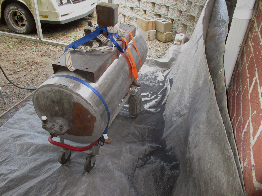
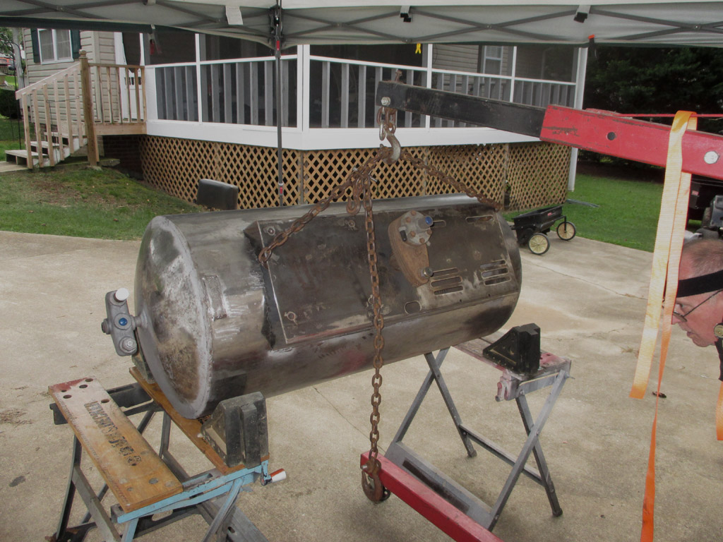
Sand blasting. A true love-hate process which requires much preparation and just as much cleanup. Love: It does remove rust completely and leave you with a perfectly prepared surface for primer and paint. Hate: the mess. This process will make the biggest, nastiest mess you've ever been in the middle of. I used my shop crane to load the tank onto my hand truck which has pneumatic tires that can roll across the gravel floor of my carport. I backed my van out into the driveway to give myself enough room in which to work.
REAR
FRONT
I laid down a tarp in my carport in an attempt to corral the impending mess. This will catch most (but definitely not all) the blast media, so you can recycle it. You need to wear a blasting hood that covers your head/neck and a dust mask. If you wear short sleeves, your arms will be covered with whatever media you're using. I took a break so my compressor could catch up because I was using a lot of air. I took the opportunity to get myself a soft-drink and snapped a couple of pictures.
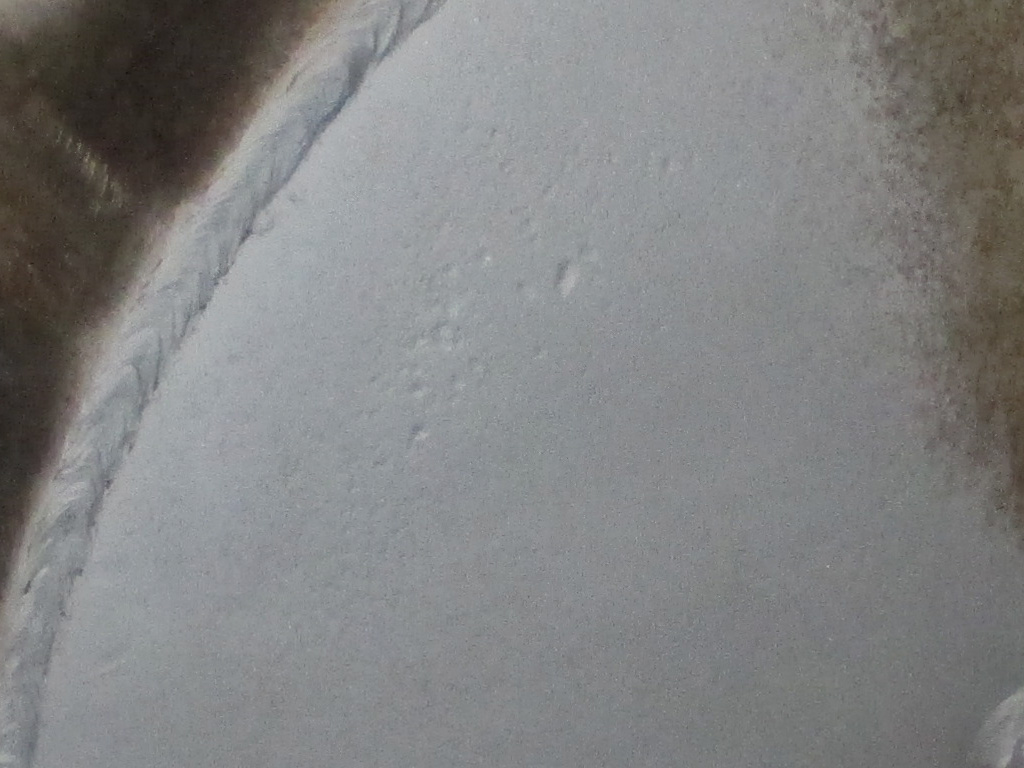
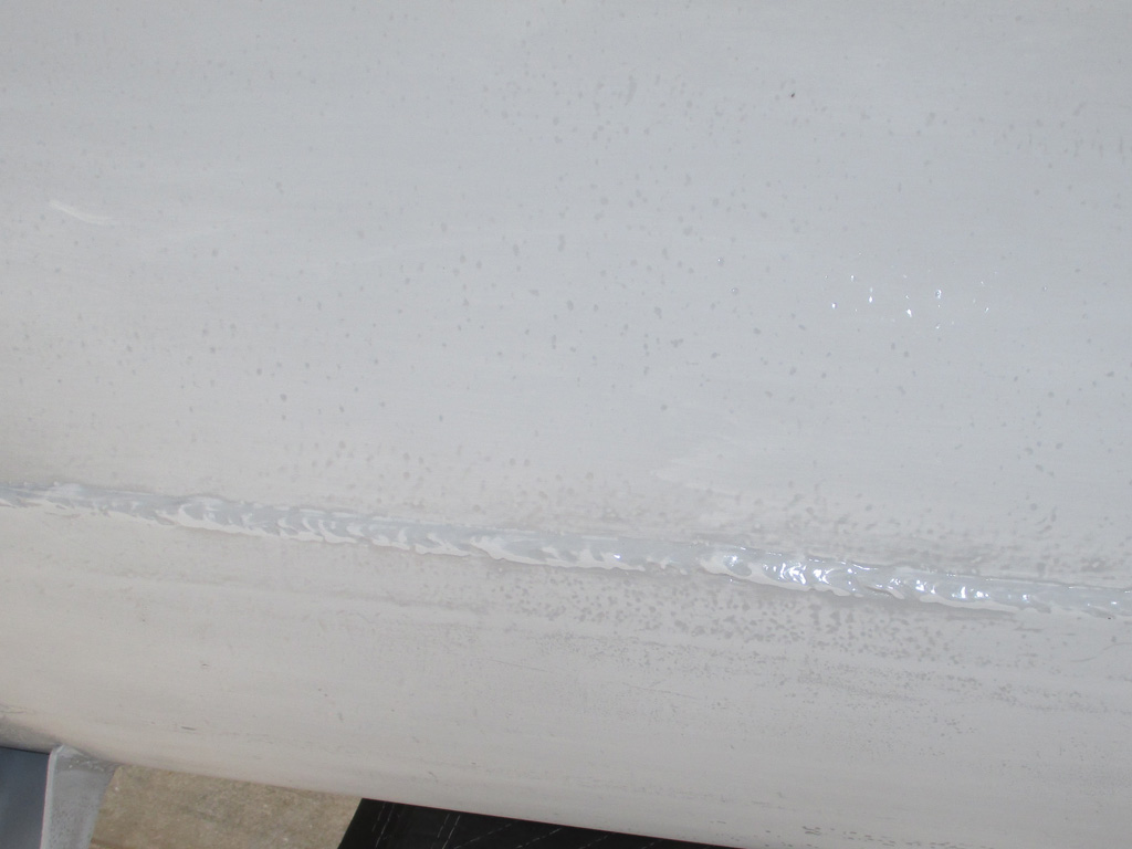
In order to ensure maximum "tooth" for the primer to adhere to (and remove as much rust as possible), I focused my sandblasting activities on the areas that had the deepest rust pits. I also paid attention to the circular welds on each end of the tank and the bottom of the tank.
In a related but failed experiment, I attempted to use soda blasting on the rust when I ran out of the Black Beauty abrasive I'd been using. This material is far to gentle to remove rust. It did an ok job on removing paint, but I'll stick to Black Beauty (coal slag) or other course material in the future. If you can see occasional sparks and feel it hit your arms, you're using the right stuff.
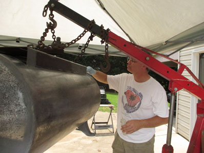
When loading or unloading this beast, it becomes a battle of wills. Will you manhandle the tank or will it manhandle you? I don't know how much this thing weighs, but I sure don't want to be in the way if it starts to fall. To that end I used the engine hoist (or shop crane if you prefer) to load this into my truck. My truck has a cap/shell, which makes this task challenging to say the least.
I need the cap to keep the weather off the tank, but carefully maneuvering the tank beneath it took 30 minutes. In the end, I put the front two feet on the creeper, disconnected the hoist, rolled the tank forward a bit and re-hooked the hoist the the rear of the tank instead of the center. Then I shoved the hoist forward until the lift arm was up against the cap back window. It just fit in the truck enough to close the tailgate.
The tank was sanded, sandblasted and then we used a grey Scotchbrite scuffing pad and some of Eastwood's Prep & Etch metal conditioner. I quickly wiped up the excess Prep & Etch with a white shop towel after scrubbing with the Scotchbrite pad and was amazed how much brown rust came off during this step.
The following day, as a final preparation, we wiped the tank down with Acetone to make sure we'd neutralized the Prep & Etch. So if you decide to do likewise, be forewarned... this is where "sweat equity" really comes into its own. I didn't tally up my hours to see what the true cost (based upon what I earn hourly) of this preparation was. I think I like it that way.
So it's a ton of labor, but in the end, I know what I've got. This was manufactured in 1945 by the Buckeye Boiler Co. in Ohio. I was thunderstruck to discover that they are still in business, have been since 1939! Their website has a picture of a modern-day Dev-Air (the company Devilbiss Air Compressor later became) compressor. I may have to drop them a line and let them know I'm restoring one of their vintage units. Would they swap out a new one to have this as a display unit? I sincerely doubt it, but stranger things have happened.
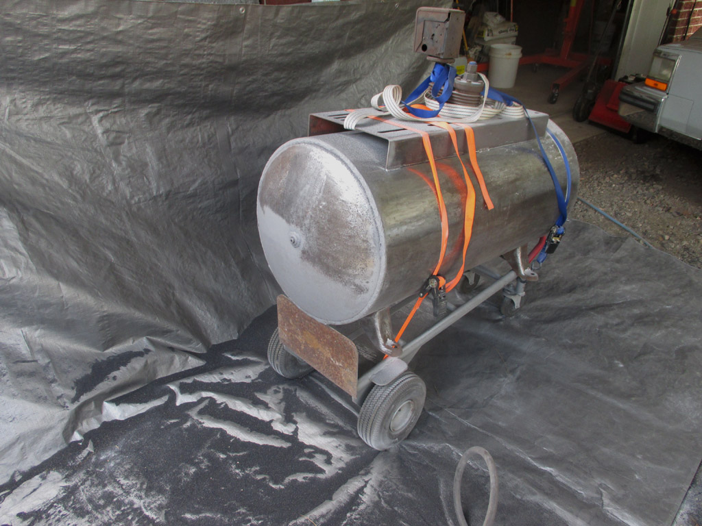
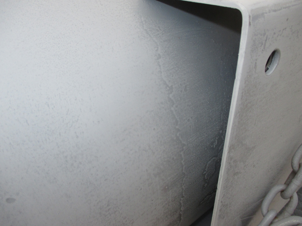
Hip, hip hurrah! Here she is, resplendent in grey epoxy primer. This was the shortest part of the operation time-wise. After all the sanding, grinding, wire-wheeling, media blasting and prep & etch scuffing we're finally ready. We had to mix the paint with the activator and give it 30 minutes to kick, but then it was time to shoot some primer!
FRONT VIEW

REAR VIEW
Now that we've got her primed, we'll let the paint cure for about 5 days or so, then it's time for a topcoat of color. Then I can take the tank and install it in its new home and make the rest of the preparations to complete the install. Seems like it took me forever to get to this point. One step at a time.
Once again we hung the tank on the lift, then slowly lowered it onto the hydraulic table cart and tipped it onto its side. The rust pits that were really prominent right after priming began to diminish somewhat as we went over the surface with 220 grit. I knew they'd never disappear completely, but that wasn't my goal. My purpose was to remove as much corrosion as possible and prevent future corrosion.
Is it perfect? Nope. Is it serviceable? When I'm finished it will be. I'm doing everything I can to be sure I have a "refurbished" durable, quality compressor. I could have shot the tank with some high-build primer (to fill in the pits), and made it perfectly smooth (with a lot more sanding) but would be purely cosmetic. I've got jobs waiting for this compressor to be up and running. So this will be good enough for my needs.
I sanded all the original paint, (what little was left) off the tank to have a good base for the epoxy. The plate that the pump and motor mount to was simply scuffed, since the original baked-on finish was plenty tough and obviously had a tremendous bond to the steel.
There was no way to get under the mounting plate, so I blended new paint into the old. The oil leaking from the pump actually helped prevent corrosion in this inaccessible area. I didn't see any surface rust beyond just under the lip of the mounting plate.
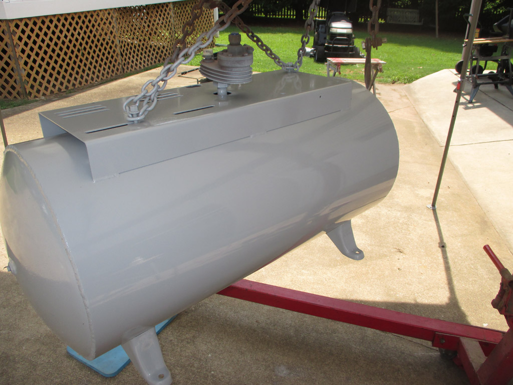
We used automotive grade urethane paint. The color was left over from a custom van paint-job. The original tank color was dark blue. Close enough. I'm trying to work on a strict budget and every little bit helps. I'll probably rattle-can the electric motor, since I don't know how long it will last.
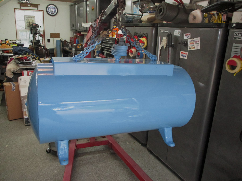
FRONT VIEW
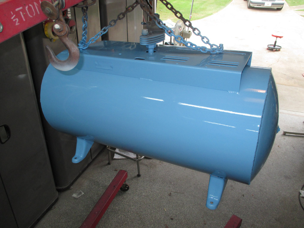
REAR VIEW
I've read dire warnings on other sites about never (lest it explode and level your entire house), using an original tank. I rapped my knuckles on a new Porter Cable and Ingersoll Rand compressor in a big box store. Ping! Ping! Ping! When I rap on this baby... dunk, dunk, dunk. This baby is thick. The pump leaking oil inside the tank should've inhibited internal rust to some extent. So yeah, I'm going to use it.
![]()
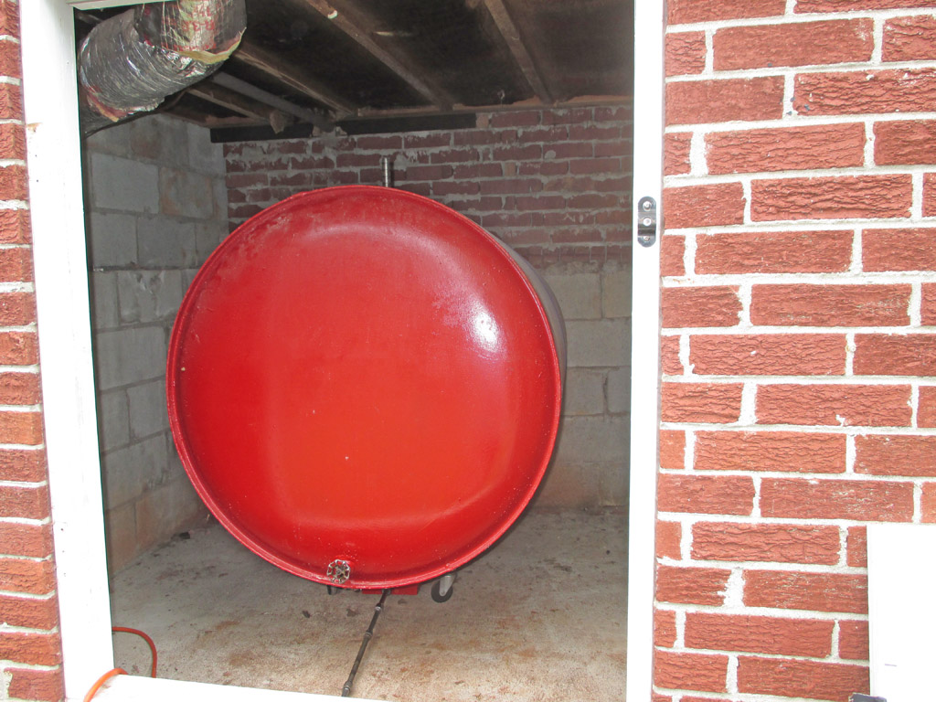
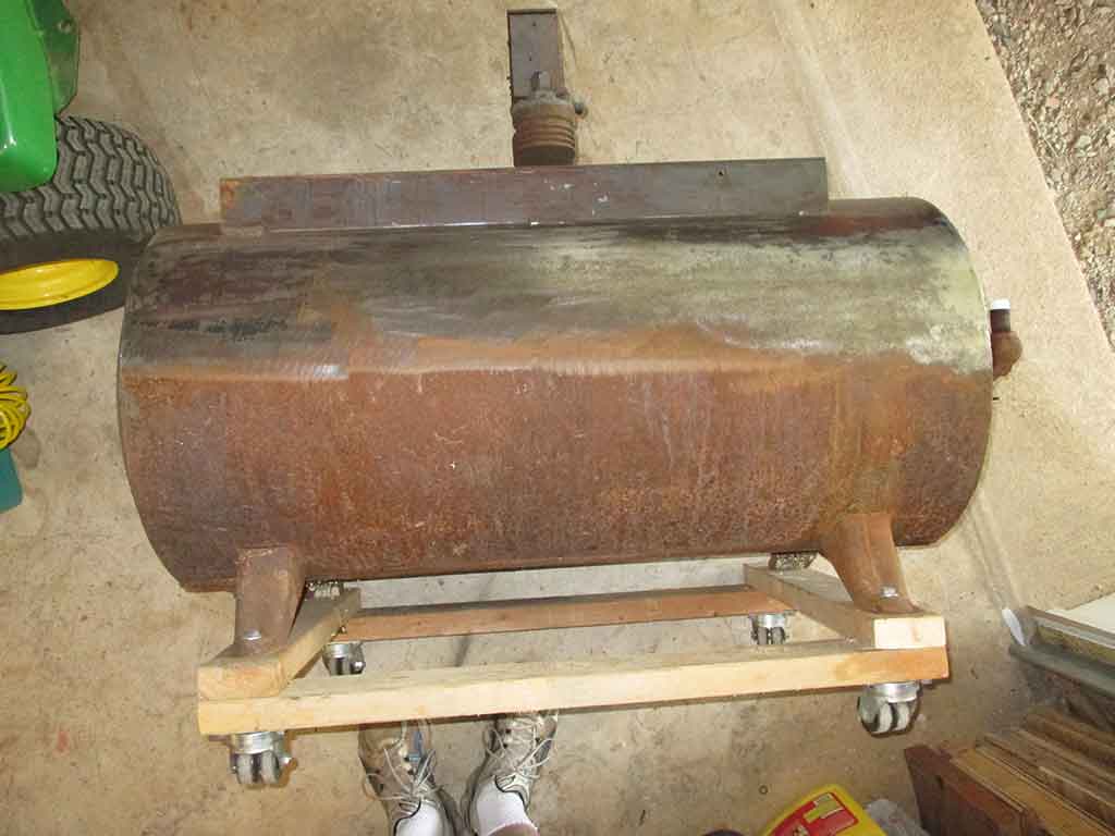
With the compressor tank curing, it was time to get cracking on the storage room where the compressor will be installed. Our house was built with a carport on one end with a laundry room comprising the back wall of said carport. Beneath the laundry room on the same level as our basement (but separated by a cement-block wall) is a separate storage room where the oil tank for the old oil-fired furnace once lived. This will be the new home for my air compressor.
Before that can happen, I really need to evict the current tenant taking up space there. We haven't used it in years, but there it sits. This needs to change. I really should have done this a while ago, but other things kept coming up and I never quite got around to it. I drained the left over fuel oil (about 15 gallons worth) one Folgers coffee can at a time. Once I did that, it became easier to move the tank without the extra weight of the fuel oil sloshing around inside.
I picked up a transmission jack at a thrift store for $30 bucks. It had a tractor seat bolted to it, so the previous owner had used it as an adjustable chair for purposes unknown. I removed the two bolts holding the seat to the jack and decided it would be just the ticket for this particular situation. Once again I used what I had on hand.
The tank was rather unwieldy until I emptied it. Even then, with a ratcheting tie down strap wrapped around it, I had to work to keep the tank from rolling off the jack, or simply rolling over and taking the jack with it. I realized I needed to remove the tie down strap in order to slide the tank off the jack and onto my tractor skids. Once I did that, the process went smoother than I expected... for once.
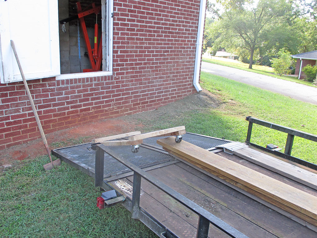
Did he say tractor skids? I backed my pickup close enough to the threshold of the storage room so I could use my tractor skids to make a bridge between the tailgate and the opening of the storage room. The jack rolled forward until it hit the inner wall, then the tank slid off it and onto the skids. My original plan had been to drain the tank once I got it up on the skids, but I quickly realized I couldn't move the tank by myself if it still had oil in it.
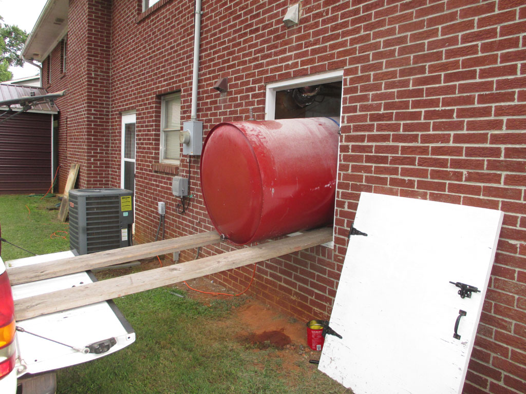
HALFWAY
ALMOST THERE
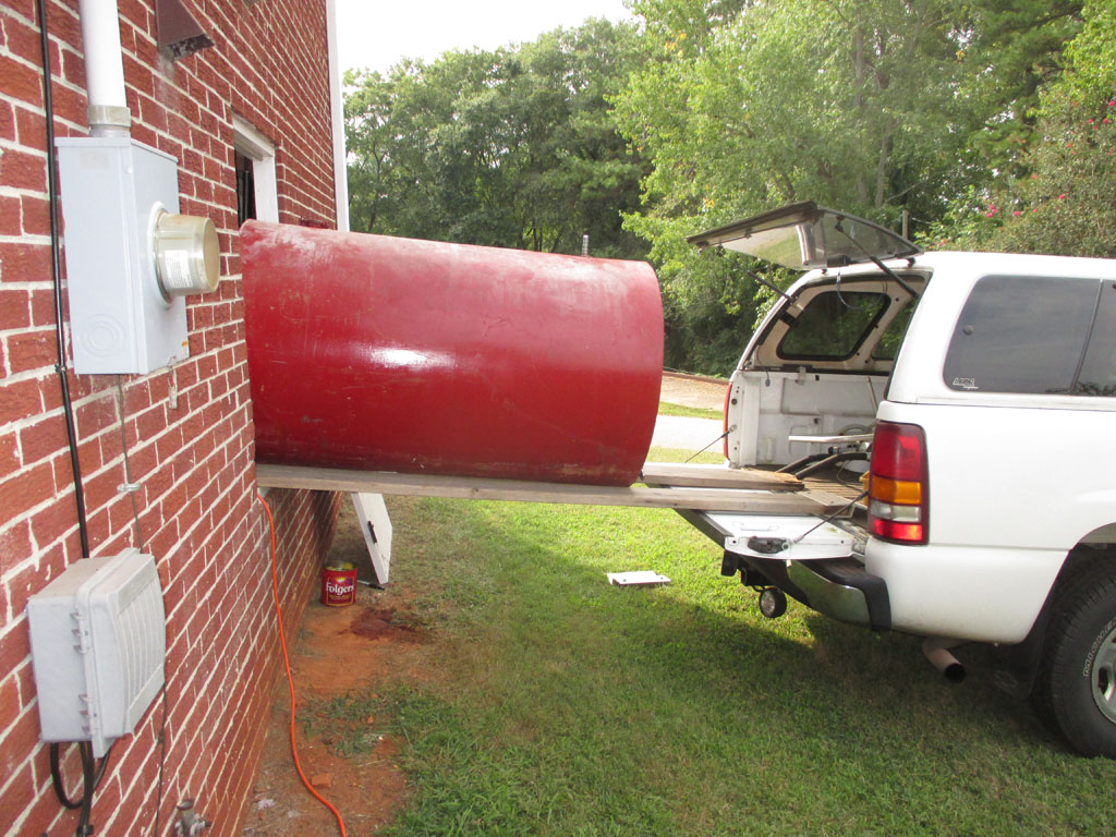
If I didn't have a cap on the bed of my pickup (and if the bed wasn't full of crap), I could've slid it into the truck bed and taken it to the metal scrappers. Instead my plan is to drop it on my utility trailer and get the job done that way. To use the pickup, I'd have to take off the cap and that's not exactly a one man job. I could rig up a couple of planks to slide beneath the cap, screw some eyebolts into each plank and use my engine hoist to lift it up and off the bed of the truck. Nah, much easier to just use the trailer.
The next step was to break out my engine hoist and lift the tank up and off the skids. Thankfully the ground was nice and solid here, some of that red Georgia clay actually came in handy for once.
Along about six o'clock, this phase of the operation came to a close. Granted I did take about an hour and a half break (if you can call mowing the lawn a break), another little chore that doesn't get done if I don't personally take care of it. Thankfully the weather cooperated beautifully for this little adventure in home ownership.
The old oil tank took a trip to the local metal recyclers. Hardly the best organized folks, they used a claw-crane big enough to grab a whole vehicle to lift the thing off my utility trailer. This left the way clear to transport my air compressor tank to its new home.
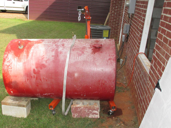
We used two sets of tractor ramps, a ratcheting tie down and a scratch-built dolly with heavy duty casters to move the tank. But first, we assembled my engine hoist in the storage room so we'd have a way to lift the tank off the ramps. A little at a time we ratcheted the tank up, pulled more strap through and ratcheted it up a little more.
As the tank reached the tipping point from one set of ramps to the other, we moved the engine hoist into position, attached the chain we used to suspend it for painting and slowly raised it up. Then we pulled out the ramps and attached the rubber feet purchased previously before slowly lowering the tank to the storage room floor.
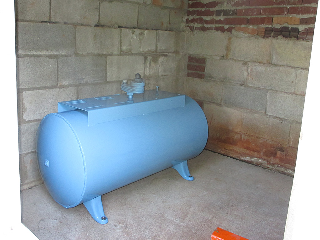
So here we are. Granted I still have a lot of odds and ends to take care of, (power for the electric motor, piping for the air) but this is a major achievement nonetheless. The backordered high-pressure piston rings are finally on their way and then I can re-assemble all these components back into one fully functional unit.
![]()
The following Monday, the high-pressure piston rings arrived! So once again I will tackle this most delicate of operations. Think I'll have at it in the morning after a good night's rest and a full cup of coffee.
Although it might be difficult to believe, each of these babies ran me $10 and change. If I can just get them onto the piston intact (particularly the ultra-fragile oil ring), I'll consider it a major accomplishment. Automotive rings being larger at least have a little more flexibility.
With cold weather settling in and the new tank in place, I returned my focus once again to the small or "high pressure" piston. First I took Mr. Dremel (equipped with a wire wheel attachment) to all the grooves in the piston since the old rings were practically glued in place. I tested each ring groove with a ring until I had them all fitting like they should. I then polished the wrist pin and the piston with some Crokus Cloth so everything was as clean as possible.
Tedious tasks like this lend themselves to soaking up some suds as the TV plays in the background. With absolutely no pomp or circumstance I simply worked each ring into its appropriate groove including the dastardly oil control ring. This time everything went smoothly and nothing broke. Yes!
In the end analysis, pretty much as anti-climactic as they come. I rotated each ring so they were 90* from each other before I move on to the next step. With no assembly guide to work from, I now had to deduce how exactly this assembly could be installed.
The piston had to be installed from the top or head side of the pump, because there was no way to do it from the bottom with the con-rod already installed due to the taper of the rod, getting wider as it mates to the crankshaft. From the topside, I could not get the connecting rod to come up high enough to install the wrist pin, then install the piston.
This left me no other option other than I would have to install the piston (from the top side) and CAREFULLY push it down into the cylinder just enough to access the wrist pin hole from inside the crankcase. One push too far and the bottom ring would come free and I'd be starting all over again. Time for another brew.
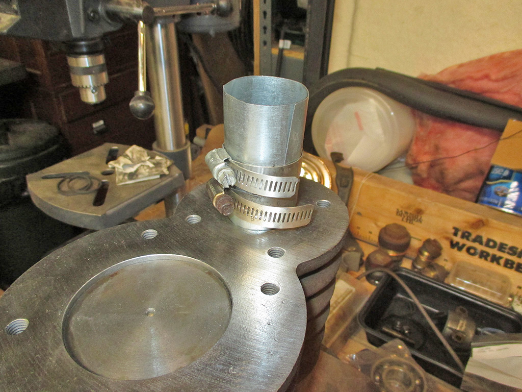
The only ring compressor in my tool-arsenal is designed for automotive use. If I wanted to install a small piston I would be needing a small ring compressor. I cut some sheet metal twice the height of the piston leaving myself enough width to go around the piston twice. I formed the sheet metal around a deep socket I had laying around and I was in business.
Then I grabbed a couple of stainless steel clamps and slowly ran each in until they were about to compress the rings. I squirted some motor oil on the walls of my ring compressor, tightened the clamps, placed the ring compressor at the top of the cylinder and gently tapped it with a wooden hammer handle. It went smooth as silk and presto, my small piston was installed!
A progress shot. Pretty much as close as I could come without courting disaster. Now, all I have to do (all- ha ha) is hold the connecting rod in place and work the wrist pin into place without disturbing the piston too much. Absolutely no pressure whatsoever.
There are actually 3 holes in the piston. Two are used for the wrist pin. The third provides access to the screw that you have to tighten to clamp down the split wrist pin end of the connecting rod. Now, while you're doing that, you have to line up the chamfer in the wrist pin with where the screw will come through.
Still with me? Good. With the wrist pin in place (hoping the screw chamfer is still lined up), I need to rotate the piston assembly so I could get the screw started. Said screw kept getting its threads boogered up, requiring removal, cleaning the threads with the appropriate dye, then trying again. Only took me about six or seven tries before it caught the threads properly. Then all I had to do was find a way to tighten the screw.
I spent hours working on this. I cobbled together a ratchet, an adapter and a screwdriver tip and tried my luck. Eventually I discovered that if I move the large piston down in its bore, then the con-rod for that piston dropped out of the way a bit giving me more access. After much trial and error, I used a long screwdriver (no pic) and found just the right angle to complete the job.
Pistons in. Wrist pins in. The crankshaft is next, but first... I have to bolt the head down in case (and I know it would happen), somehow during maneuvering the crank and rods a piston would go beyond the top of the head. Then I'd have to break out the ring compressor to fit the piston back in... much better to simply bolt the head back in place first.
Because I'm super anal about such things, I just couldn't resist cleaning off the surface rust inside the valve chambers of each valve. Was this really necessary? Considering the amount of rust flakes and dust I vacuumed up after using a variety of wire wheels/brushes I would say yes. All it would take is a rust particle to jam open one of the spring-loaded plates and I'd be in deep doo-doo. So I grabbed a cold one and got to work. Didn't take all that much time and I have more confidence in the job now.
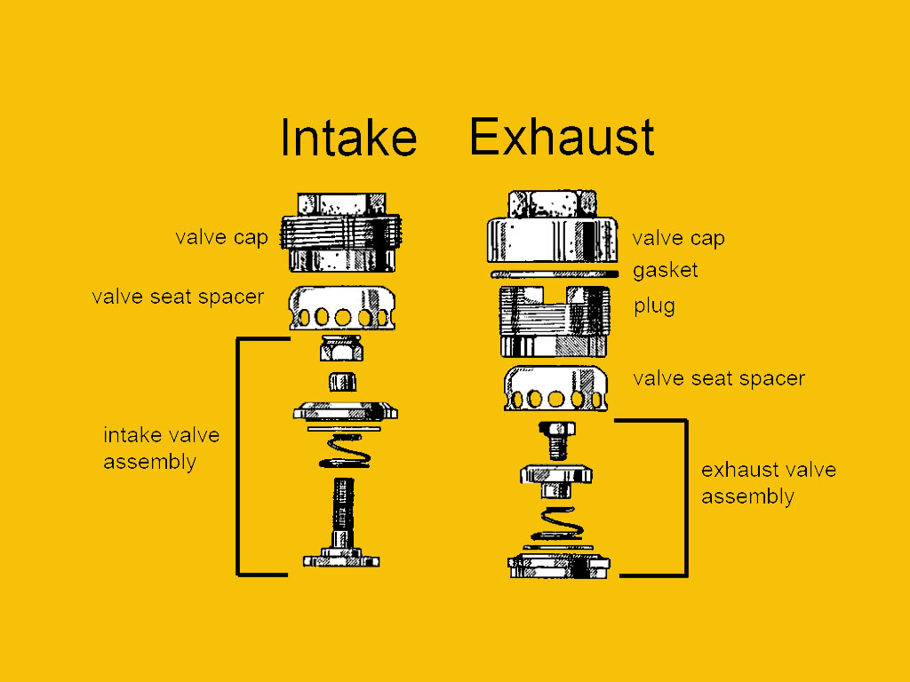
Each valve is held in position by a dome shaped cap technically called a "valve seat spacer." Three of these valve seat spacers are held in place by some really beefy brass plugs, capped off with a copper gasket and cast iron valve cap. Only the low pressure intake valve (pictured left) is held in place by a one-piece flush valve cap.
Not only am I lacking a screwdriver big enough to tighten the brass plugs, but each slot is perfectly square while all my regular screwdrivers have tapered tips. What to do, what to do? So... I got creative. Looking at the screwdriver in my hand, the little light bulb went off.
LARGE BRASS CAP
SMALL CAPS
By using the square shaft of the screwdriver, I now had a tool I could use. It was a perfect fit and gave me the leverage I needed to tighten everything down! I discovered that my 1/2 inch open end wrench was a perfect fit for the smaller caps and added a second wrench as an extension for more leverage. What can I say... it worked for me.
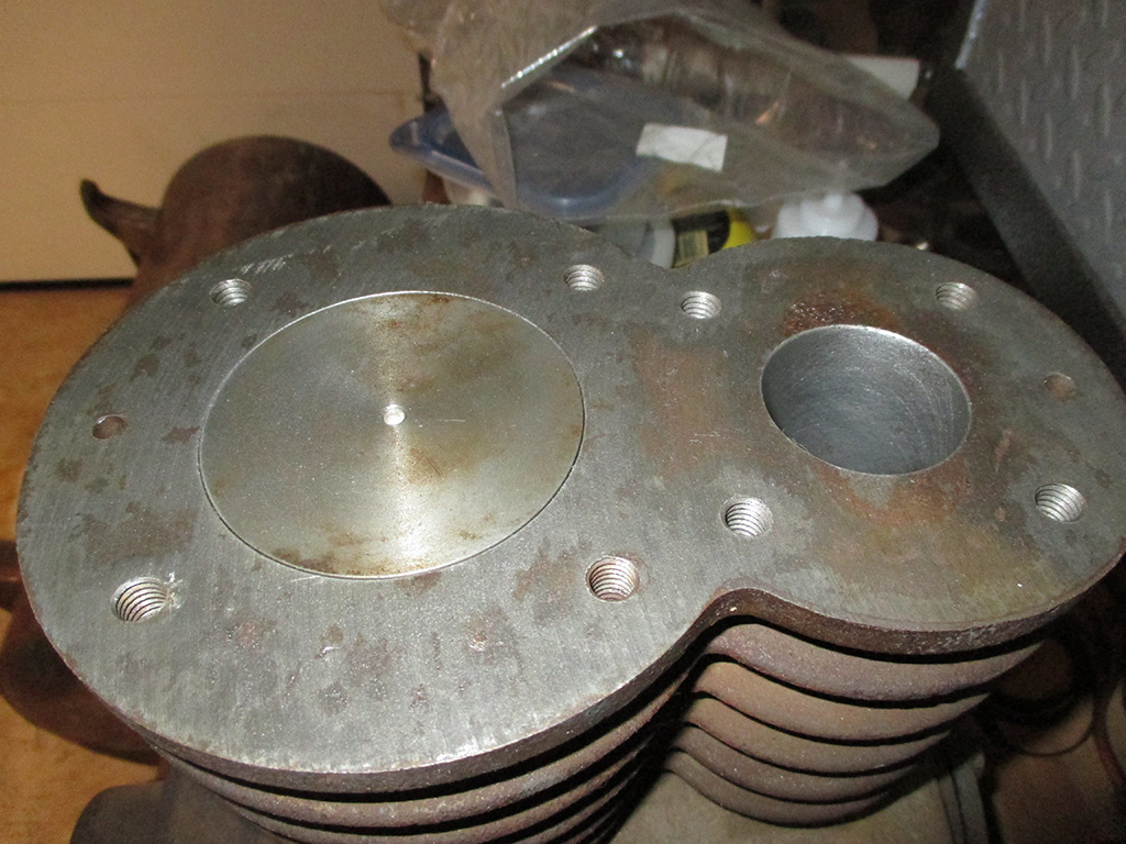
It took awhile to get to this point. Wire wheels, course steel wool and a final wipe down with brake cleaner left me with a head about as corrosion free as I could get it. I used the same basic process on the pump "block" to get the best gasket mounting surface possible.
One other downside to restoring a machine as old as this. The only source I found for parts had valve rebuilding kits and that was it. No other parts available, don't even ask. So... what do you do about all the gaskets necessary to put it all back together again? You order some gasket material, break out the old Exacto knife and get to work making your own custom gaskets. It's a bit time-consuming, but it's the only choice in situations like this. However, you can use this opportunity to make sure everything fits with precision.
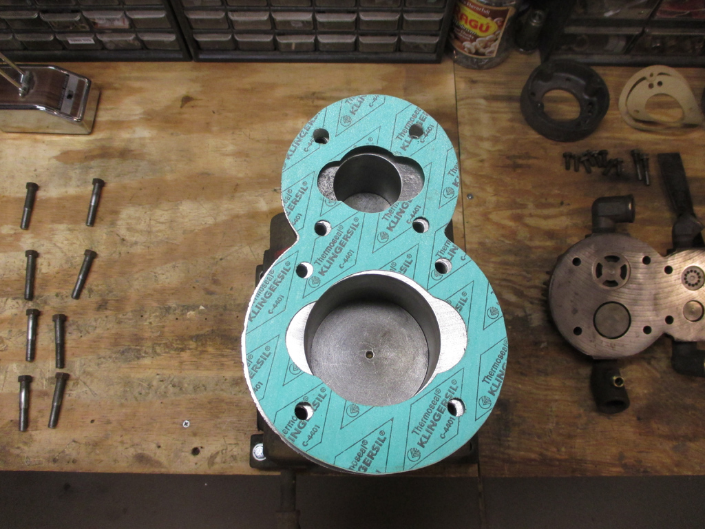
HEAD GASKET
THE REST
When I removed the head bolts and pulled the head, I found a handmade head gasket that blocked part of the valves. I made certain that my gasket fit as exactly as I could, so the valves could work as efficiently as possible. The original gaskets crumbled to bits during disassembly, so I had to measure each part requiring a gasket and make those from scratch too. The two plates that hold the crankshaft bearings in place used 1/128 thick vegetable material for gaskets. After much deliberation, I used 1/64 gasket material, which should be close when compressed.
Really rolling along now. At this point I have to find some specifications to tell me how tight to make all the head bolts as well as the connecting rod nuts. So far I've downloaded an exploded diagram of the pump and a parts list, but no torque specifications. Just one more hurdle to cross.
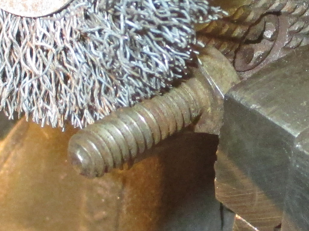
Now that reassembly is in full swing, I like to make sure all the hardware is nice and clean. To that end I put each bolt in my vise and hit it with the wire wheel in my drill. Doesn't take long at all and in case you're wondering, the greasy bolts get blasted with brake cleaner first so there's little chance of me spraying myself with millions of tiny little grease blobs. Nope. Not me.
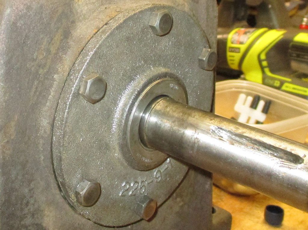
I had to carefully thread the cleaned and oiled crank back into the block, holding the connecting rods out of the way and making sure the "oil splash rings" (arrow) were in the right place at the same time.
I found some specifications online(for a similar Army air compressor found on the net), the connecting rod nuts = 25' pounds. I torqued the head bolts to 45' pounds only to discover the numbers 35 stamped into the heads of a couple of the bolts! That figures. At least none of them snapped, so in the end... I left them as they were and moved on.
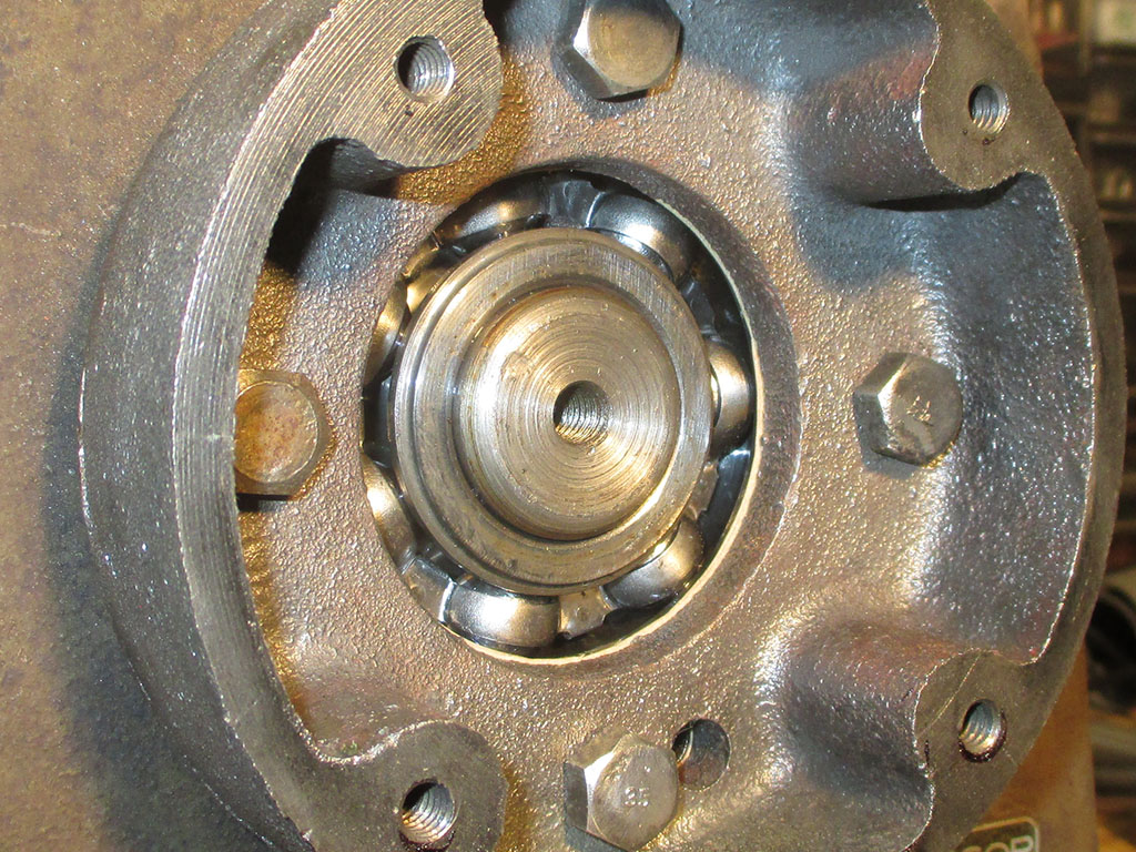
I used a rubber mallet to carefully seat the new ball bearing into the rear pump race. I had some High Tack gasket adhesive (a super-sticky, stringy, purple-colored goo), laying around that I applied to one surface, giving me enough time to assemble the parts.
I didn't have a socket or pipe on hand to install the new oil seal, so I took a brass drift pin I had laying around and carefully tapped all around the circumference of the seal, slowly working it into place in the front cover.
I put a dab of oil on my finger and spread a very light coating on the outside of the seal as well as the inner rubber inner lip of the seal to ease the installation. When the sound changed I knew it was fully seated. Job done!
So... crankshaft in place (check), connecting rods torqued to the specs I'd found online (fingers crossed), front cover, gasket and oil seal installed (check) it was time to move to the rear of the pump and begin reassembly of the "centrifugal pressure release" unit. bum BUM BUM!
I pulled everything apart and cleaned every piece thoroughly before reassembling the various parts including 10 pea-sized steel balls that fit into openings in a gear-shaped brass "ball cage." (Ouch!)
Below left is the assembly that goes inside the centrifugal pressure release housing that I bolted to the back of the pump in the previous step. My hand made gaskets kept wanting to curl back up even though I kept them pressed inside a book after making them. Once again I broke out the High Tack gasket adhesive and installed the remaining components.
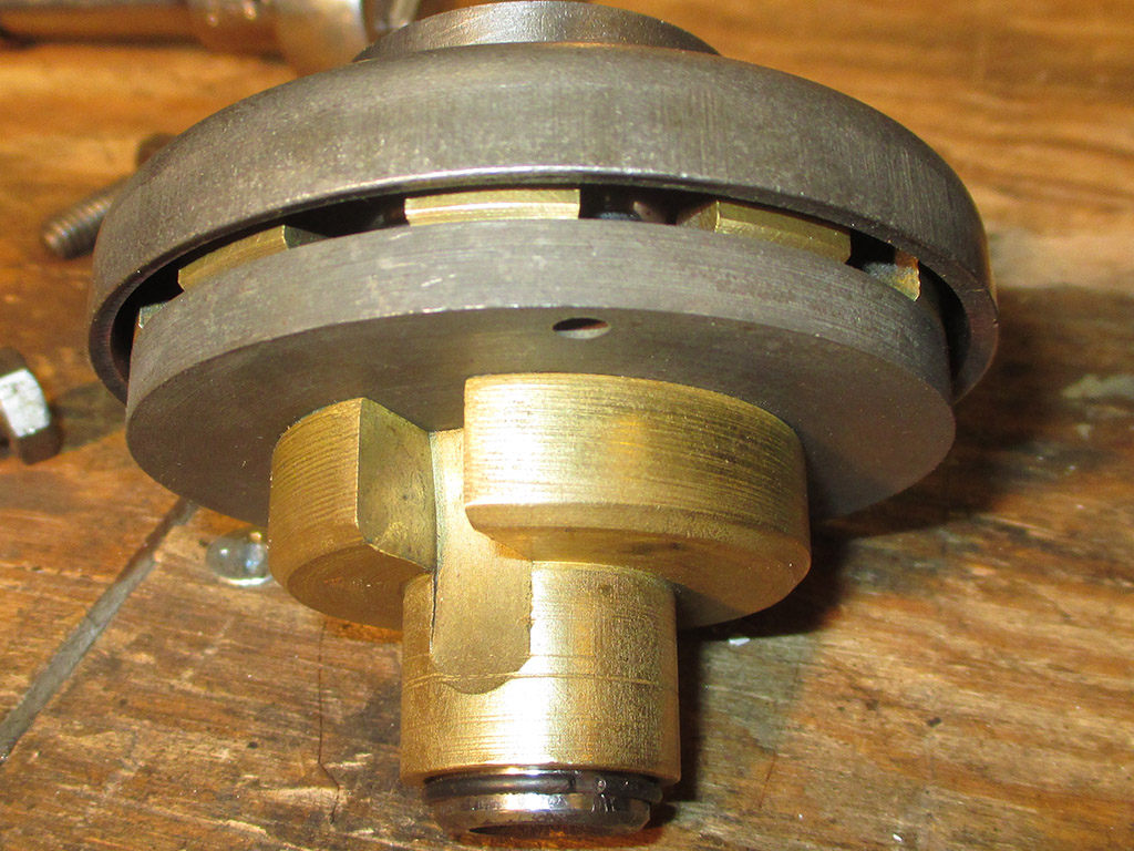
CENTRIFUGAL ASSEMBLY
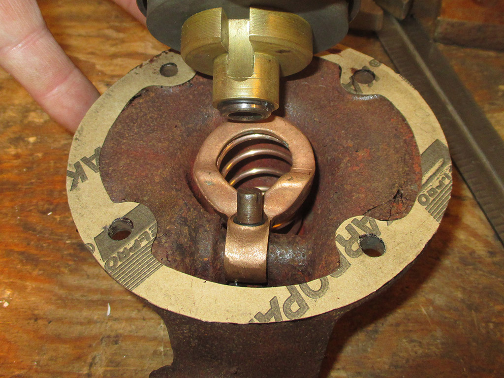
CENTRIFUGAL HOUSING
The notch in the brass piece aligns with the screw holding the copper spring unit. I did not remove the spring-loaded assembly. I sprayed it with brake cleaner until it was clean and shiny and called it done. The hard part was holding the assembly in place while trying to get that first bolt started. A long thin screwdriver (as third hand) helped me hold things in place.
Despite my best efforts at cutting and trimming out all the holes necessary, the bolt holes were still just a bit off. The gasket adhesive wasn't about to let me remove the gasket, so I came up with another solution that worked just fine.
"Captain - the centrifugal pressure release is about to blow!"... not the way I put this baby together! All I had left at this point was the installation of the "hand hole" covers located on each side of the pump.
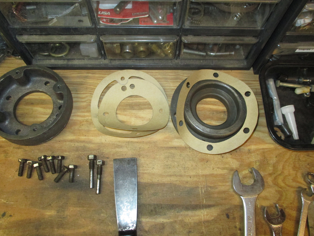
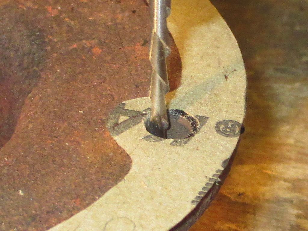
When I disassembled things originally, these plates had maybe 1/8" thick cork gaskets. The gasket material I had on hand was thinner, but designed to be gas and oil resistant. This required much measuring and intricate Exacto knife work. Making curves in the material requires using the tip of the blade. I snapped off three tips in the process. This is why I buy my replacement blades in bulk.
The gasket material I used here had been rolled up in a drawer, probably for 20 years (give or take) so I had to put weights on the material to cut out the openings. I used a step drill bit at a slow speed to make the bolt holes in each of these gaskets. The gasket adhesive really earned its keep here. Arrows = gaskets replaced.
It had been so long (hey, I'm a busy guy) since I first tore this thing down that initially, I had the centrifugal pressure release installed improperly, with the copper tubing facing straight up. Thankfully I'd taken many pictures of the compressor prior to disassembly, so I easily fixed my little goof. All that remains is to clean the pump and paint it.
![]()
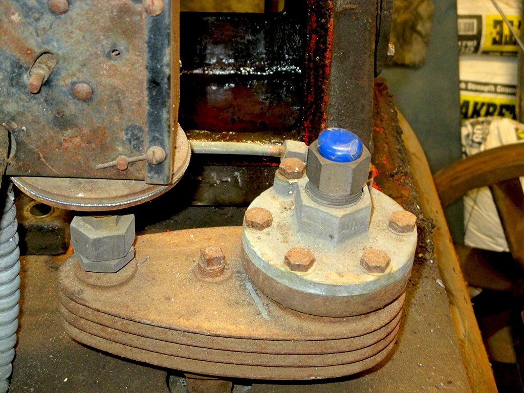
The Hook Up:
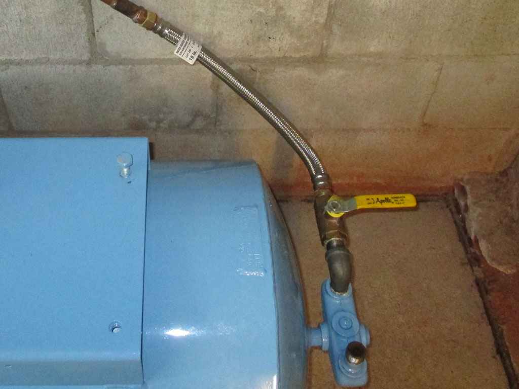
With the tank mounted on rubber feet, a certain amount of movement is possible. To avoid unnecessary movement which might adversely affect the copper joints, a section of high pressure water heater hose was selected to address this issue.
Using a 90* elbow & a pipe nipple, the new valve was added to the system. With 2 other ports available, I plan on using one for the air pressure gauge and the third will be used for the pressure relief valve as originally equipped.
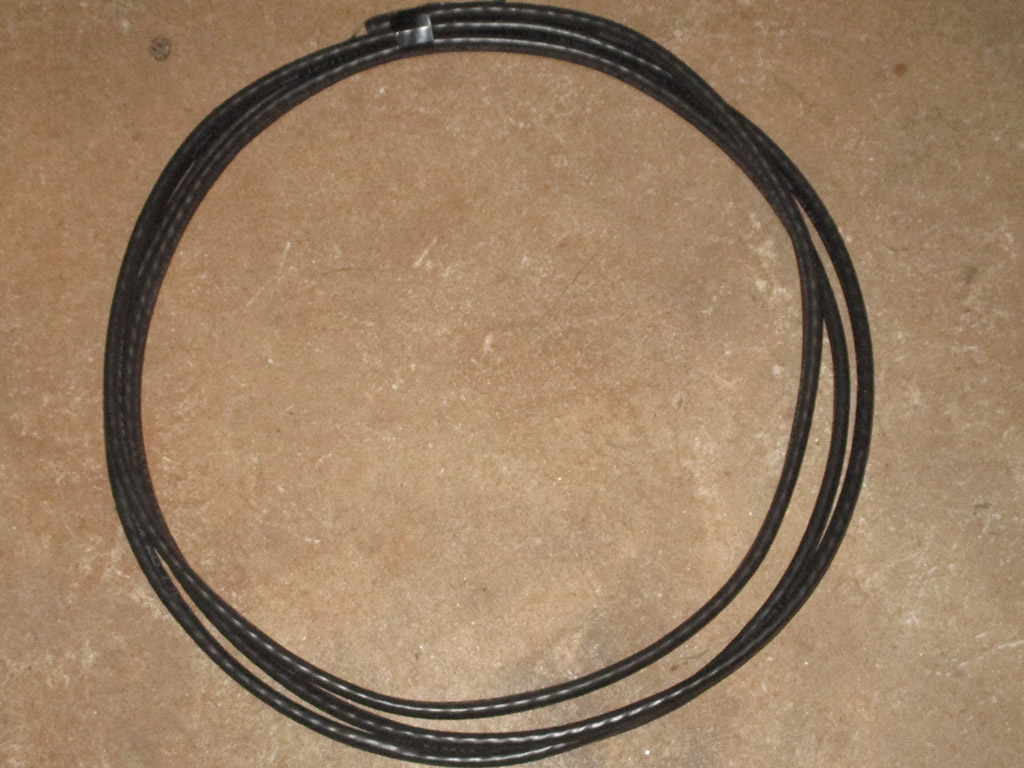
The air compressor is only part of the equation. Once compressed I have to have a means of getting the air where I need it. After exhaustive research, I concluded that copper pipe (type L thick wall) was still the cheapest way to go, coming in significantly cheaper than black iron pipe or galvanized pipe. I spec'd out a rigid blue (not the coil that never straightens completely out) compressed air piping kit with 3 20' sections, 2 unions, drop fittings, 90* elbows and outlets for compressed air and came in right around $175 dollars. The coiled systems I found were all 100' minimum and I only needed 50 feet.
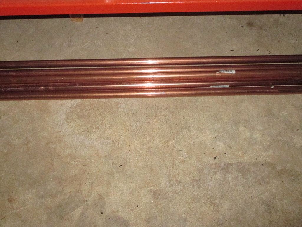
PIPE: $140
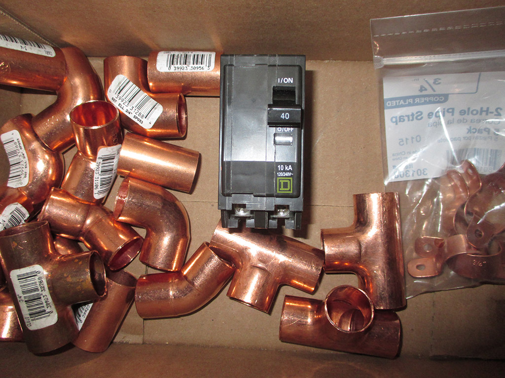
FITTINGS: $26
BREAKER & WIRE: $30
Although these aren't directly related to the compressor rebuild, I decided to calculate them into the overall costs at the top of the page, since they are essential to having a fully functional compressed air system. At $205 dollars total (tax included), I did exceed the price of the rigid pipe kit, however my trip to Lowe's also netted me the electrical stuff so at this point it's Apples to Oranges, and who knows what other stuff I'd have needed with the other system. Decision made, job done.
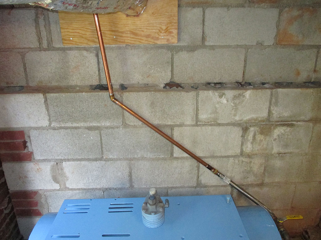
A union, a 45 and a 90 enabled us to run the copper from the compressor into the basement where the bulk of the piping will be run. Since this will never be seen or displayed, we chose function over form in running the copper pipe through the plywood.
I installed the plywood as a dress-up for the hole someone made in the cement block wall (from the looks of it they must've used a sledge hammer), for the heating duct and water supply lines. A little insulation and plywood on either side of the wall gives a more finished appearance as well as a point of entry for utilities such as copper pipe and electrical lines.
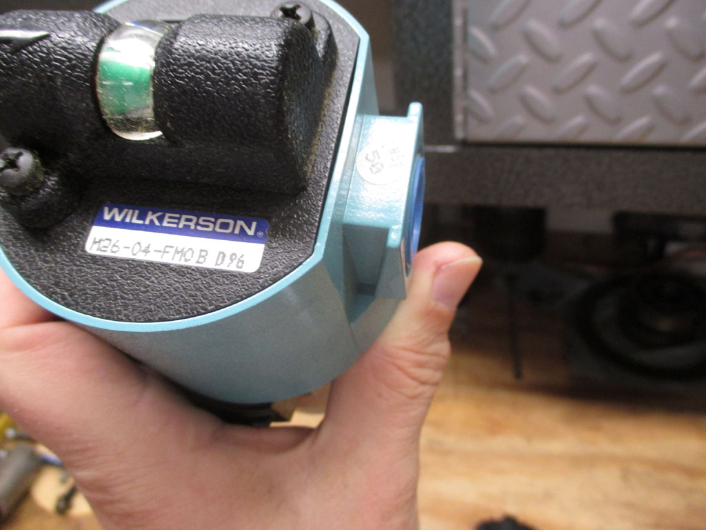
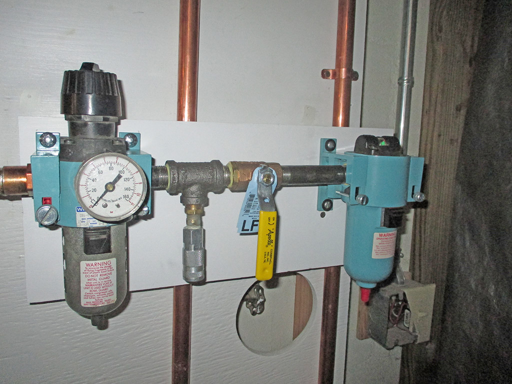
As always my goal was to purchase quality equipment to use for this project. When comparison shopping for compressed air components, you soon discover there's a wide range of prices from ludicrously expensive to suspiciously cheap. I finally settled on the Wilkerson brand made (of course), in USA. I chose what I could afford, hoping I've chosen good "middle of the road" quality equipment.
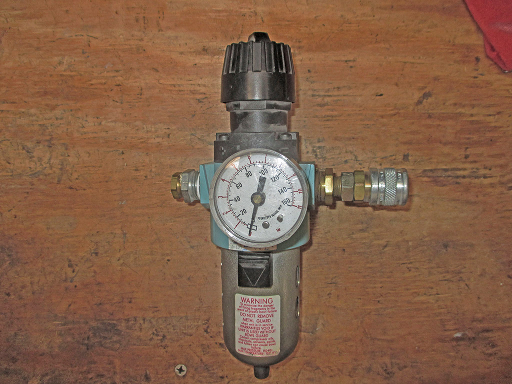
REGULATOR: $50
FILTER: $90
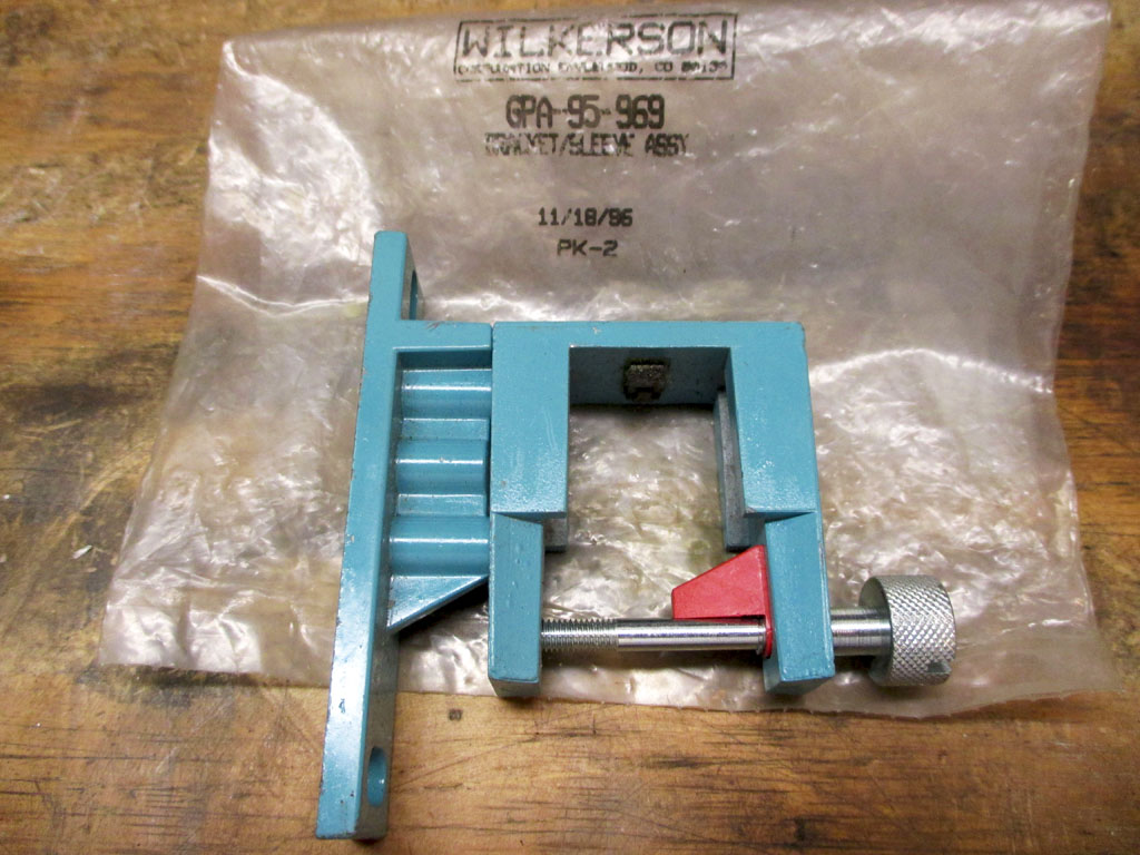
BRACKETS: $55
The only downside I discovered is that every item is sold separately. There are two mounting brackets for the regulator and two for the moisture filter. The range of prices for these brackets (see price list at page top), varied wildly from cheap to steep, but they are proprietary and I didn't want to rig everything up with hose clamps and zip ties. My goal was to make a professional looking installation, but this is getting ridiculous!
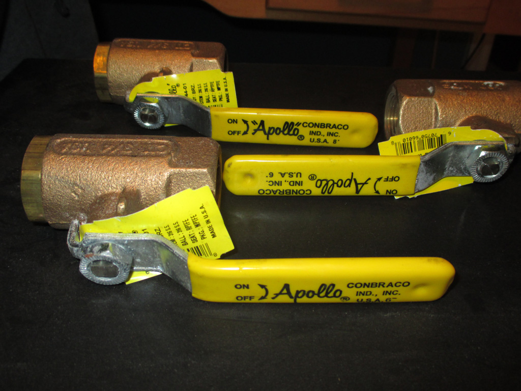
Costs continued to spiral as I blew another $45 bucks for 3 made in USA ball valves. I originally planned on using all three on the "control panel" I plan on building. Instead we used one as the master shut off valve right at the tank.
My original plan did not include drainage for water that will condense in the pipes as the hot air from the compressor cools. With this in mind I decided I better put my ideas down on paper instead of trying to design everything in my head. I'll probably need another valve (maybe two), before all is said and done.
With 50' of copper pipe between the compressor and the outlet, I figured I only needed 2 loops to cool the air and help get rid of moisture. I only have a tall narrow space to use so the feed line will be on the right, with the loops to the left. The last down length will have a T fitting angled forward so the regulator and moisture filter can be mounted horizontally in front of the copper pipes.
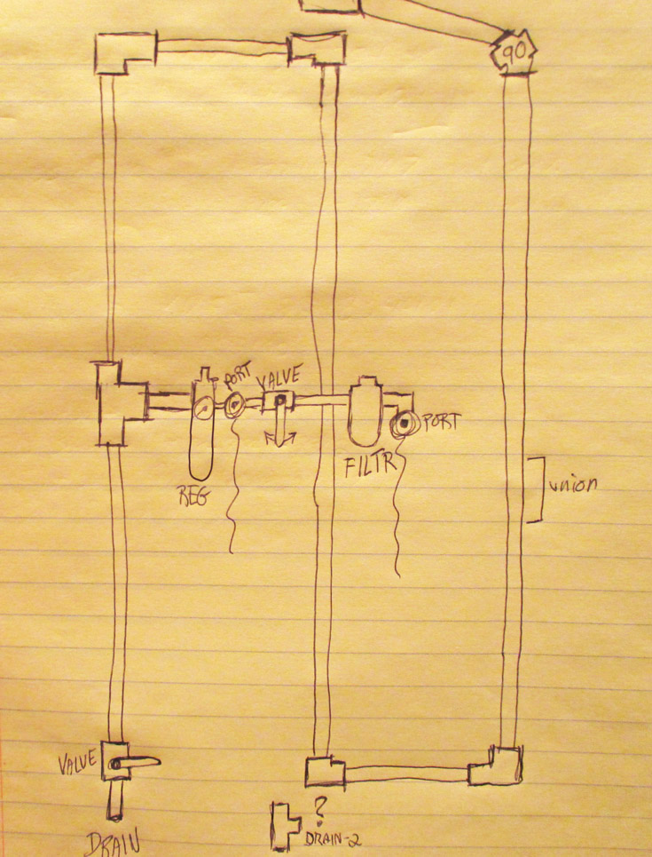
THE PLAN
THE EXECUTION
I used two short sections of 2x2 as standoffs to which I will mount the horizontal 1x6 board that will serve as my control mount. Space is at a premium as I only have a 20" width to work with for the regulator, port, ball valve and moisture filter. I may need to modify this plan, but hopefully sketching things out first will make the actual construction process go smoothly.
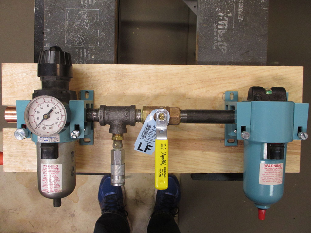
From concept to reality. This work-in-progress is 20" wide, which is the total width of my copper pipe mounting area. These fittings are nice and tight and I used pipe dope to ensure a proper seal. Before doing that though, I spent a lot of time seeing which combination would work best. I tried all short connections but couldn't tighten them due to interference with the brackets on the regulator and filter. A 4.5" length of black pipe was needed in front of the moisture filter, to allow enough room to swing the ball valve handle from off to on.
I've had to make several modifications to the mounting board of this fiendish conglomeration of parts so far. First I bored a hole for the feed line to come forward to the regulator. I'm a novice at sweating pipe and probably would've burned the board had I stuck with that design. I changed that to a slot so I can slide the board into the pipe after I sweat everything together. Oh, I almost forgot, the valve seen here... another $14 bucks shot in the ass.
After wasting 2 hours blasting just the head of the pump (due to the inadequacy of my current air compressor), I took the pump to a sandblaster local to where I live. After bringing it back home, I kept it covered to help prevent flash rust while waiting for warm enough temperatures to paint. Amazing how fast a task can be completed if you just have the proper tools.
It seems like it's been forever since I first brought the "Monster Compressor" home to my humble little shop. My stubboness at wanting a Made In USA unit led me down this path, and the restoration of the compressor has taken an inordinate amount of time to complete. When you're a home owner you really have to deliberately carve out the time to get things done.
The pump was originally dark red, later over-sprayed black. When I painted the tank blue I felt that a red pump just wouldn't look right. The new electric moter is basic, industrial black, so painting the pump black to match was a no-brainer.
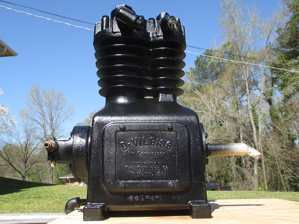
NAME PLATE
CENTRIFUGAL PRESSURE RELEASE
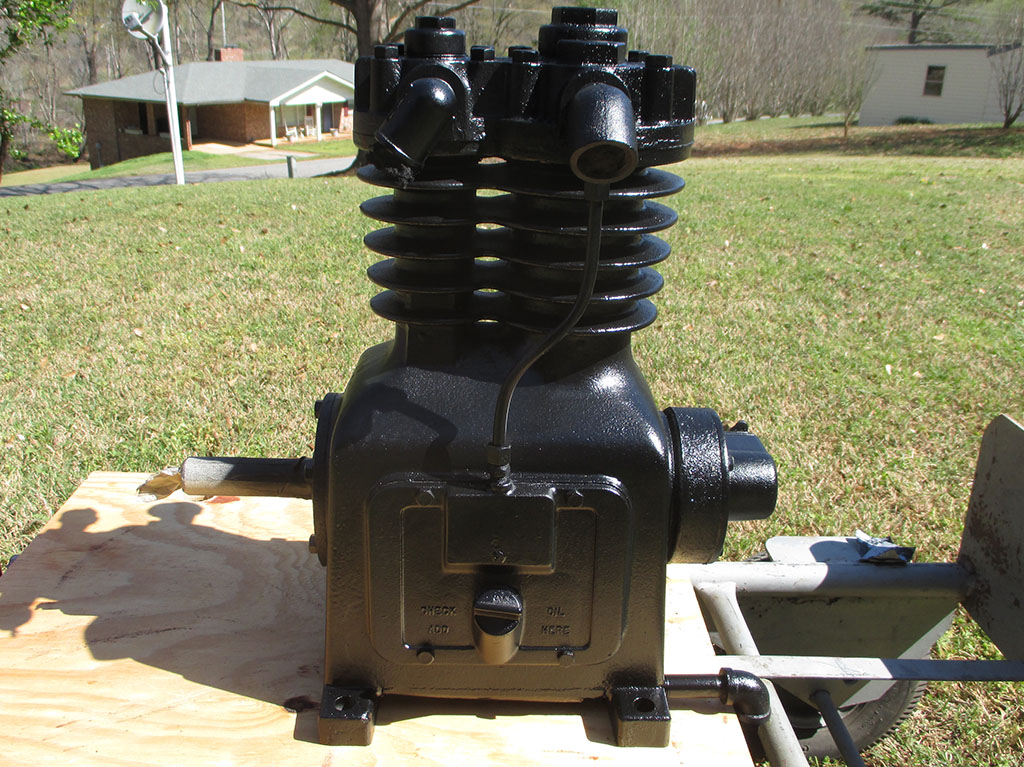
OIL FILLER
All that remains to be done at this point it to source a new key for the flywheel shaft and I can actually mount the motor and pump back onto the tank! I'm really looking forward to having enough air to run all the tools in my shop including my paint gun and sandblasting cabinet.
The sandblaster I stupidly took all my parts to (in retrospect), also paint what they blast... for an additional fee of course. As incompetent a job as they did on my small-block Chevy cylinder heads (sand literally in every nook and cranny of the head), I really can't fault them for the job they did here. Maybe they do better work if they get the job of painting the item as well, who knows.
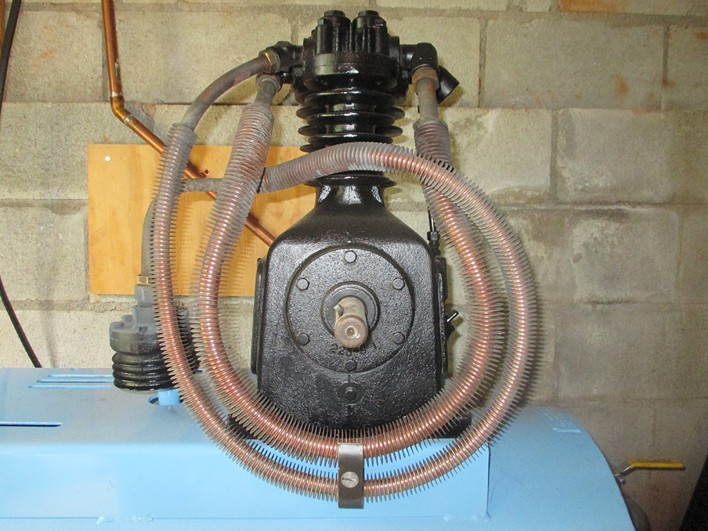
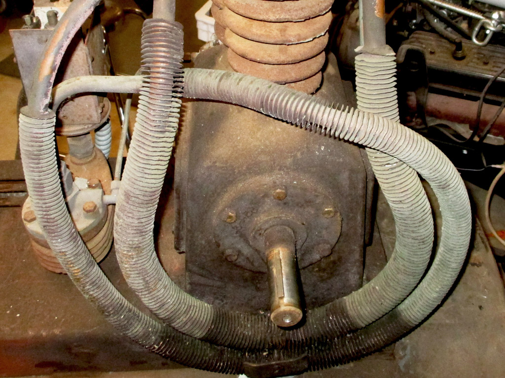
It took me the better part of a day to clean off the cooling coils. The oil seal around the shaft had worn out and oil flowed down the shaft and was flung onto the coils by the flywheel/cooling fan. My goal wasn't to have them be bright copper, that happened when I discovered the best way to clean them was a spritz of brake cleaner followed up by a wire brush to get in between the "disks" of each cooling tube.
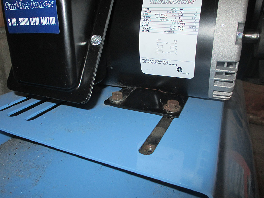
This is the new electric motor I will be using to power the pump. Compared to the original (1.5hp) this is a 3hp rated 220 volt motor. I had the original electric motor tested and it still works fine. My plan is to move forward with the new motor and hold the original in reserve just in case. I was able to reuse the original threaded plates for the new motor bolts needing to only drill two new slotted holes in the compressor's mounting plate.
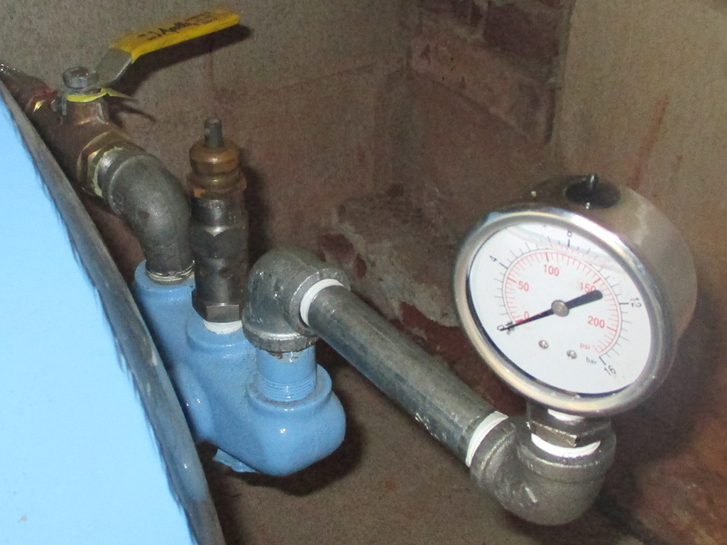
Along with the shut off valve, this side of the tank has provisions for a safety blow-off valve and a pressure gauge. The plan is to re-use the original safety valve, which can be adjusted although I'm not sure exactly how that's done. My goal was to keep the original pressure gauge, but it probably needs to be re-calibrated which I plan to do as soon as I find a place that does that sort of thing. In the mean time I have a Harbor Freight import serving temporary duty. I looked for an have been unable to find a new USA made gauge so far and this will at least get me operational.
At the end of the day this is where we stand. Plumbing of the tank is completed. Original flywheel installed. New electric motor, pulley and belts installed and initial adjustments made. Fabrication of new motor mounts ate up the clock as well as making a run to Lowe's for some electrical wire to complete the wiring in of the motor.
Below is a schematic of the OEM air filter housing. All I have is the housing and the baffle. My efforts at finding the appropriate filter media and felt (not to mention the retainer wire) have netted me butkus. From what I've been able to gather, the purpose of the filter is air flow not necessarily extreme micron filtering.
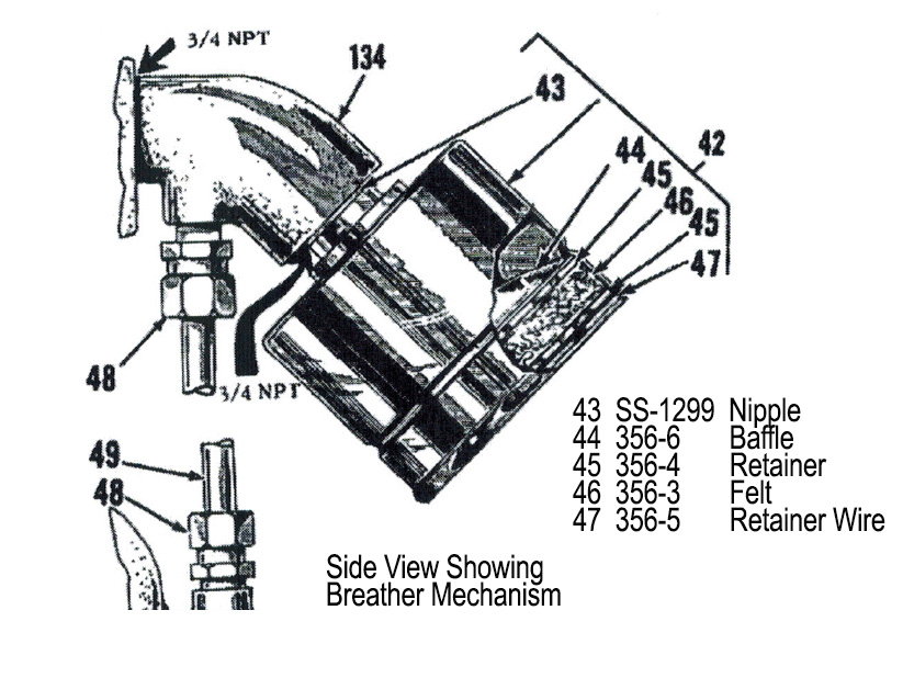
ORIGINAL
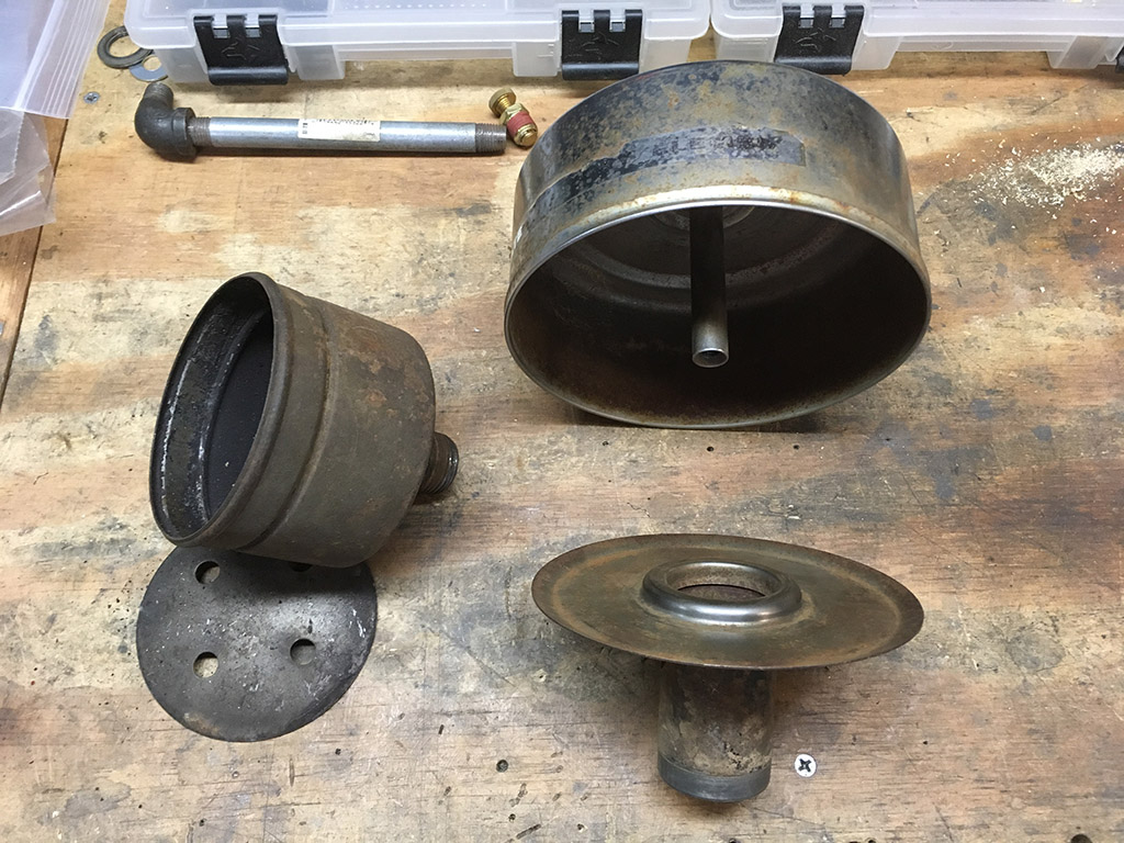
REPLACEMENT
MODS BEGIN
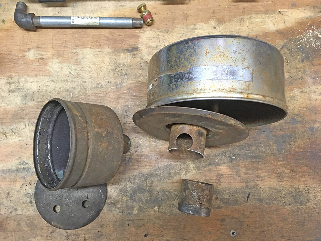
I rooted through my junkpile parts stash and came up with a small engine air filter housing. The neck was too tall for my application, so step one was to cut off what I don't need.
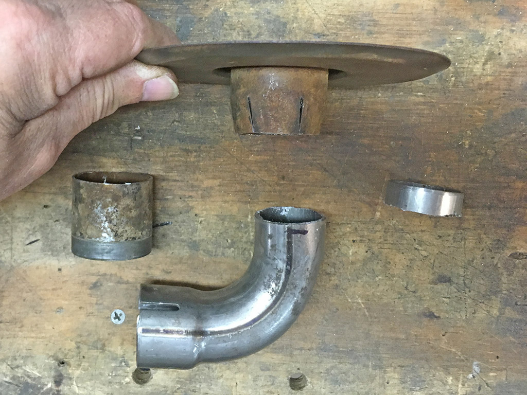
I found a 90* exhaust elbow leftover from some other project (also too tall for my intended use), to make a transition from the "too big" air filter neck to the 3/4 NPT pipe that goes into the pump. This necessitated some small pie cuts out of said air filter neck so it would mate with the elbow. My goal will be to weld the pie cuts closed and then weld the result to the elbow. Admittedly a convoluted approach, but I'm using what I've got laying around to get the job done.
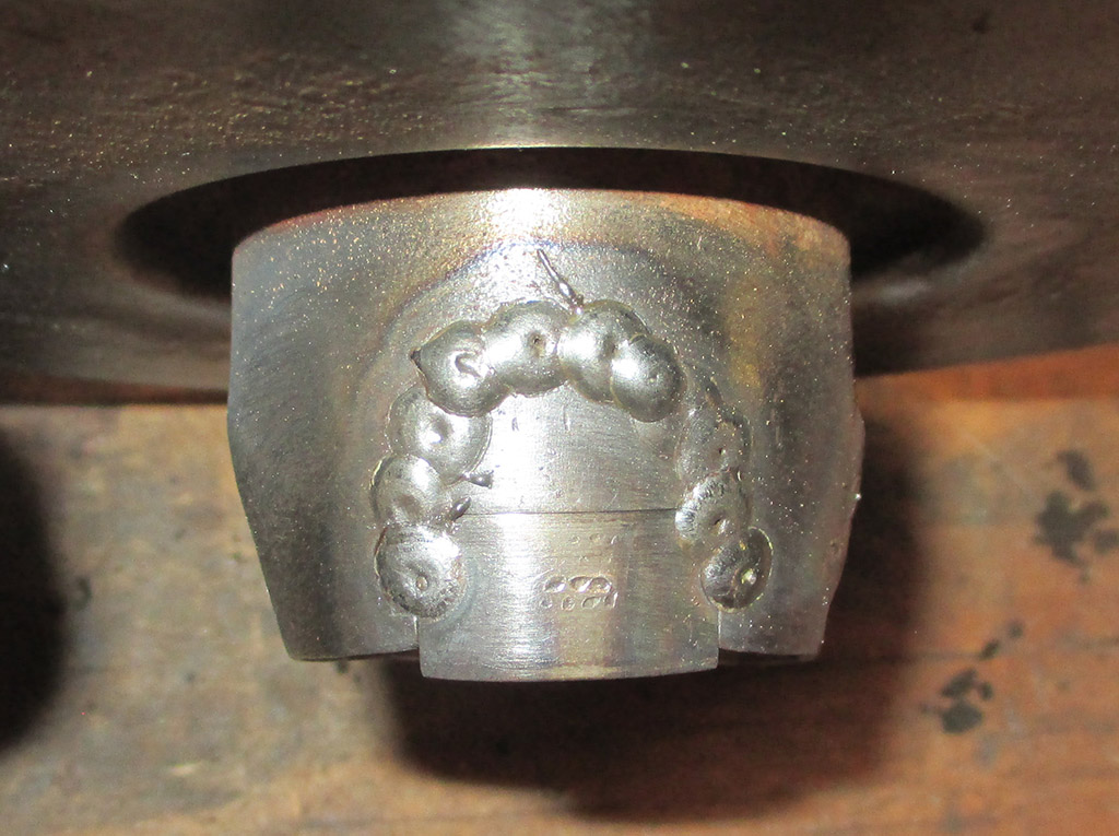
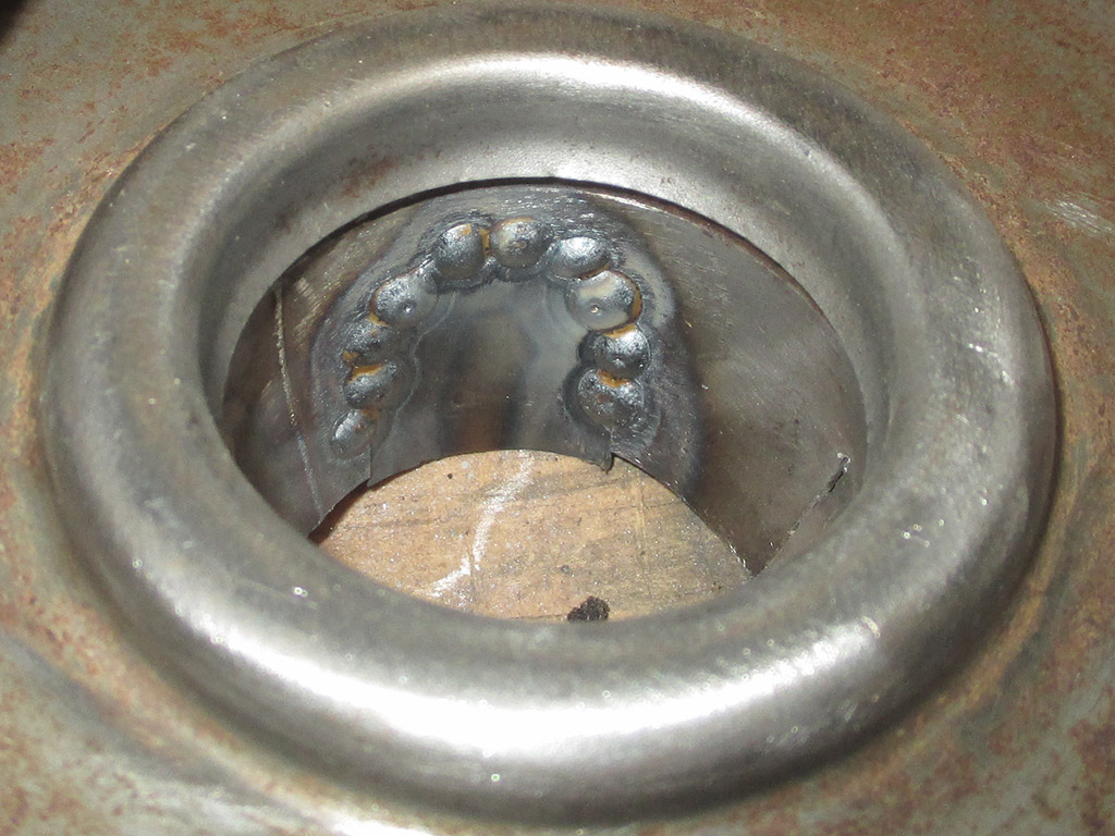
After finally stealing a day for myself, I was actually able to make significant progress on the air cleaner housing project. I cut a patch out of the section I removed and trimmed it to fit where the original engine had a crankcase breather tube attached. Since I was working with the same gauge steel as the van intake tube, I used that as my starting point. A setting of 3 on the speed and E on the voltage gave me good penetration on all the welds.
PATCHED
SOLID
ASSEMBLY
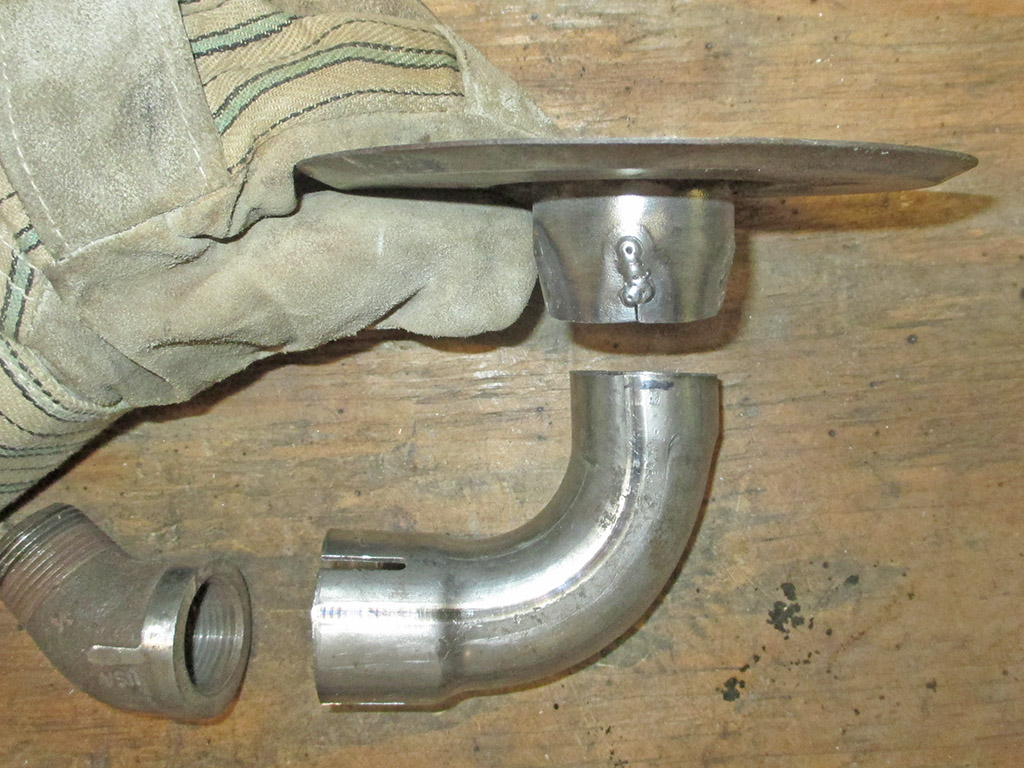
Next I worked on the fitment of all three of the pieces I am using to create my new air cleaner housing. With some judicious grinding, I was able to get the 45* pipe fitting to fit inside the 90* tube. I have a bit more to do then a I can clamp my new assembly to the cast iron pipe. All I have to do then is procure an air filter element and I'll be in business.
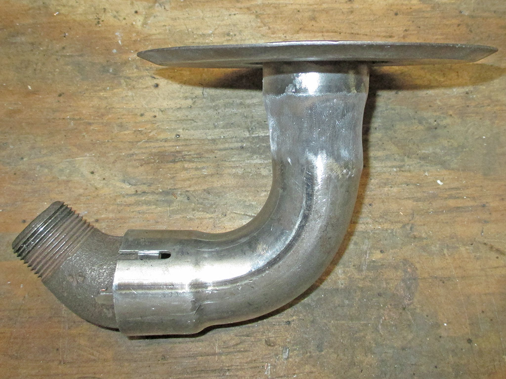
What you see here is the result of roughly 4.5 hours worth of fitting, welding and grinding. I ended up with a concave section where the wide air cleaner neck mates up with the exhaust elbow. I could clean up the transition with a coat of Bondo, but I'm not sure if I want to do that at this point.

© Copyright 2009 Brian Petruska | Top | Body Shop | Upgrades | GM Performance Parts | HTML Now! | Apple | Comments |