
87 monte ss - Stable Mates

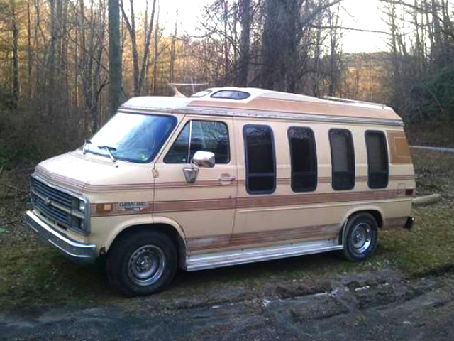
Spring 2013 So... I've had cars, I've had trucks, so what other type of mid-life-crisis mobile (laughingly, semi-seriously) is a car nut expected to drive? Well, I decided to go retro and buy myself a rolling time machine of sorts... what could possibly be better for that late 70's vibe, than a VAN? OK, so it's a conversion van instead of a true '70's built from scratch "shagin' wagon" but I think it's cool.
I was cruising Craig's Lust (a truly freudian type-o if ever there was one), thinking about the issues that revolve around transporting my elderly parents, so I found myself in the van section to see what was out there. I found a conversion van for $800 with a rod knock. When I went to pull the trigger later in the week, the ad had expired.
After pointlessly driving around the small mountain town listed in the ad, I reluctantly threw in the towel and moved on. In moving on, I actually came across a better deal. It was almost twice the price, but was drivable and seemingly had unusually low (later verified to my satisfaction), mileage for a 1984 vintage vehicle.
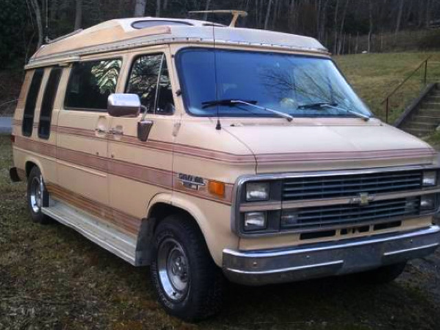
What we have here is one 1984 G-20 Chevy Van, that received the full high top conversion courtesy of Quail Creek Custom Vans (Levonia Georgia long since defunct), back in the day. High top, custom interior, power windows & locks... a real highway cruiser.
The trip home from where I purchased the van was a good 2 hour trip (not including stopping for dinner), that was as uneventful as possible. The van drove well, didn't try to hesitate on taking off from a light (or try to stall sitting at one), essentially driving just as it should. When going up a grade the transmission downshifted smoothly with little pressure on the gas, then upshifted again at the top of the grade, situation normal.
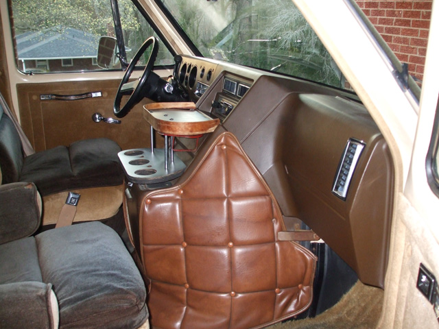
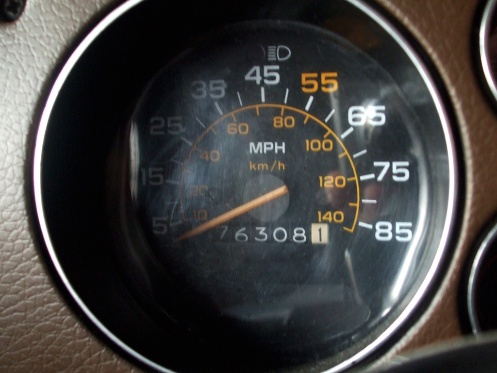
The cockpit, illustrates why I believe the sellers statement regarding 76k original miles to be true. The upholstery isn't excessively worn, the carpeting is in good shape and the brake pedal pad, although old isn't worn through on one side or the other, usually indicative of a high mileage vehicle.
The dashboard isn't cracked or excessively worn and the instrument panel functions normally. One issue I found was that the passenger side safety belt had been replaced at some point with a universal shoulder harness. At some point the mid section of the belt had been cut almost completely through by a razor blade or something.
A more direct shot of the dash. I lucked out in this arena as well, since (by all accounts) the full instrumentation seen here was optional equipment. I've never understood Detroit's preoccupation with idiot lights. I much prefer knowing something is going wrong vs. HOLY SHIT BALLS... SOMETHING JUST WENT WRONG! If I can just get the temperature lever freed up (my trip home was a real foot-roaster) I'll be a happy camper.
UNMOLESTED DASH
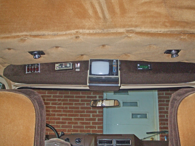
OVERHEAD CONSOLE
My current plan is to keep the overhead console, but rearrange the placement of some items. The Jensen stereo the van came to me with is obviously a newer after market unit with a digital clock built in. This kind of clashes with the built in clock in the overhead console. The van was probably delivered to Quail Creek Custom Vans without a radio, which would be cheaper and let them offer their own options.
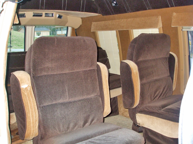
Row 2 captain's chairs. Conspicuous in this particular shot is the rear airconditioning unit, located above the rear bed/3rd row seat. I've never had one of these before (but I've never owned a van before either), according to the previous owner it's a necessity in the hazy, hot & humid summers the south is famous for. Again, the upholstery is in pretty decent shape, no holes, no tears, no cigarette burn marks. The elastic of the pocket of each seat back has sagged a bit over the years, but I may decide to change things in the future, so not a big concern for me. I'll give it a good going over with my shop vac and we'll be ready to roll in no time.
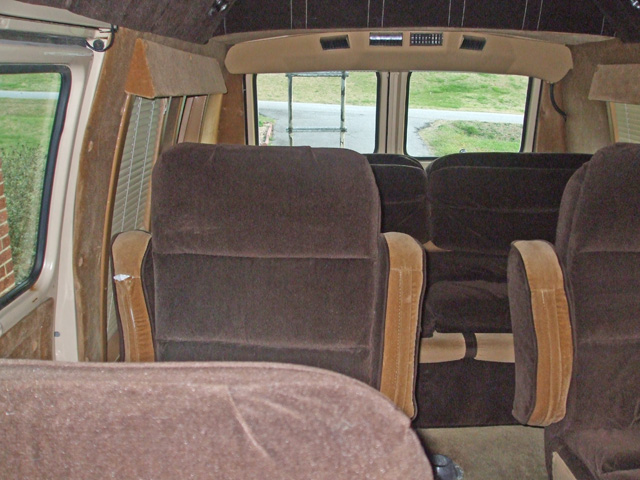
The third row of seating is actually a convertible rear bed/3rd row seating arrangement, currently configured as a third row of upright seats. I've seen some vans where this unit is all electric, but then you have the added worry of electric motors, screw drives, gears and whatnot all of which add weight to an already heavy vehicle.
The "shakedown" drive did turn up a significant issue. After a few miles together, I learned that there seemed to be a time lag between stepping on the brake pedal and the point where before actual real braking began. A good grip on the wheel is also a good idea as this baby becomes a real handful (veering unpredictably from side to side), at that point.
Custom Touches
Valve Covers
July 2017
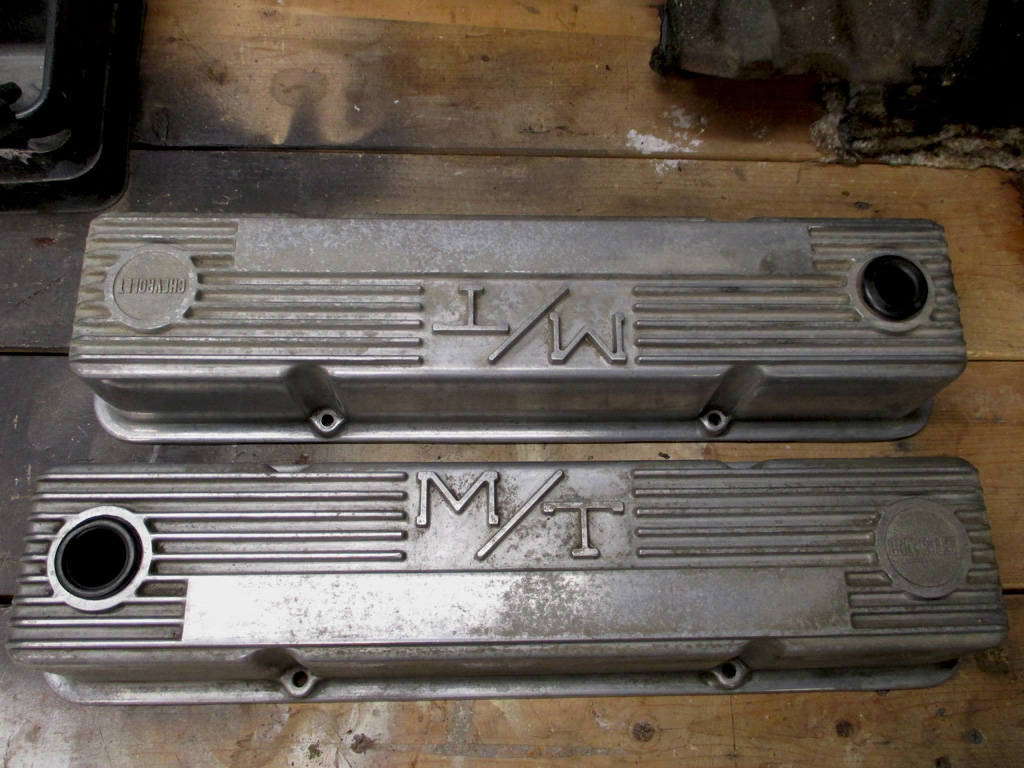
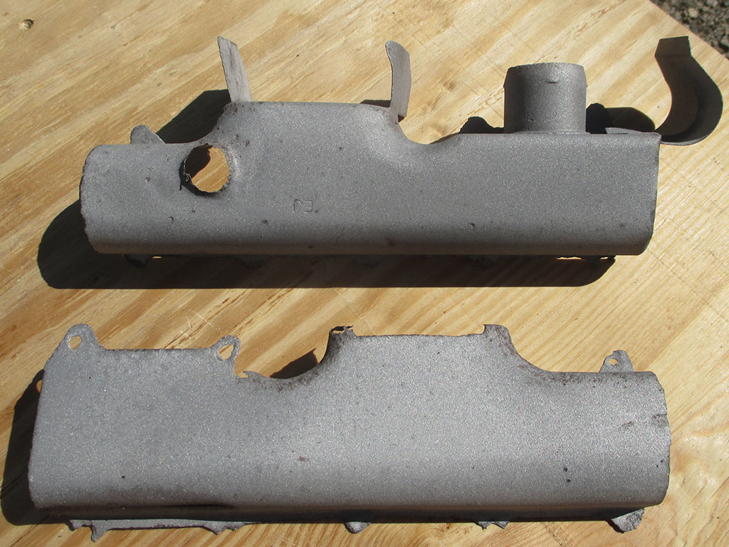
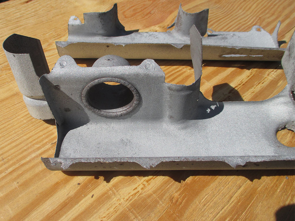
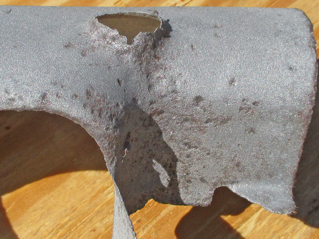
What do you do when you discover rust holes in the gasket mounting flange of your valve covers? I suppose you could weld 'em up, paint 'em up and slap 'em back on... but what if they were pretty much beat up anyway?
Rather than go that way, I decided it was time for another upgrade to the engine compartment. I picked these up used, since I thought they'd go with the retro theme of my van. Once I polish these up, they should set off my freshly painted heads nicely.
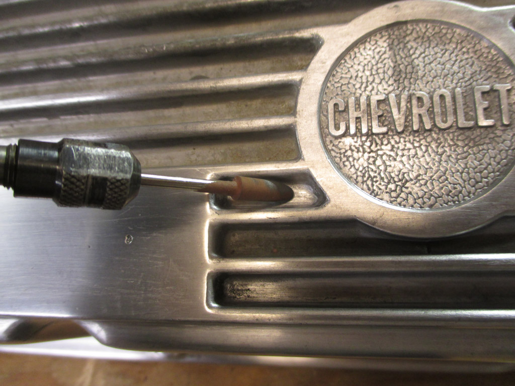
Shortly after unpacking my new bling, I briefly pondered leaving them as purchased with the "patina" of age they had. Needless to say, that idea was short lived. My next idea, restore them and use some "Chevy Orange" paint between each rib as a nice added detail. Of course, the more detail you want to add, the more time you have to spend on the preparation of the part.
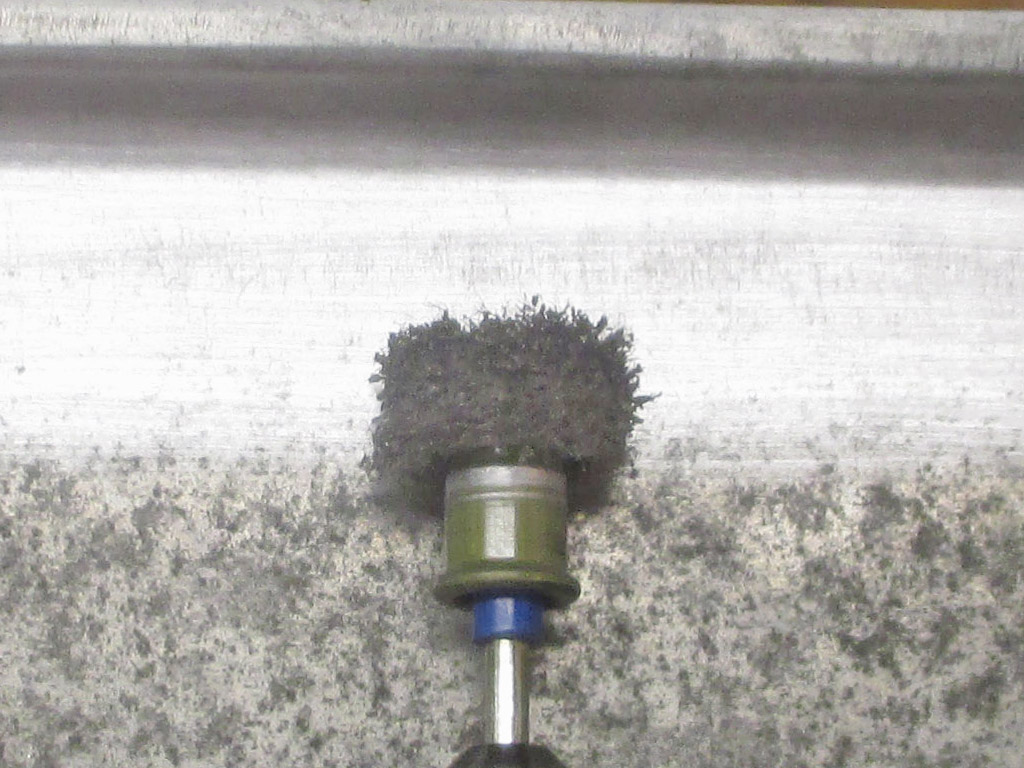
ABRASIVE BURR
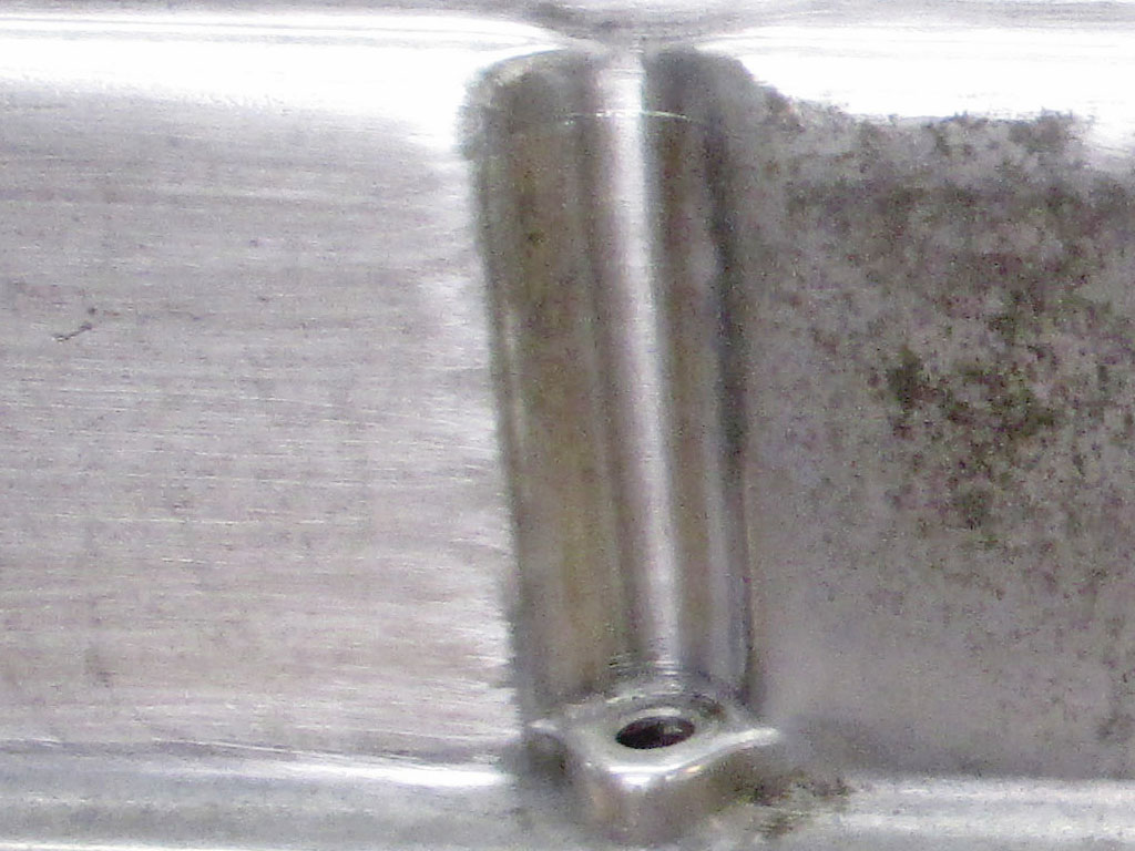
PROGRESS
I would need to scuff between each rib, mask off each outer rib plus the flat sides of each cover, and shoot it with some VHT Chevy orange. Give each cover a couple of coats, then carefully rub the paint off the top of each rib with some Lacquer Thinner. That's a lot of extra work, but would give me a vintage custom look if I could pull it off. First I have to get everything clean. To that end, I broke out my trusty Dremel, installed one of my EZ Lock coarse abrasive buffs and went to town removing the dark stains from the aluminum.
I could still see some of the staining after using my Dremel, so I decided to see what some 600 wet/dry sandpaper would do. The 600 grit eradicated the last of the stains but left me with a satin finish. I fully expected this, resigning myself to make subsequent passes, moving to a finer grit with each pass. I also did all my sanding wet, which cut down on the dust and extended the life of the sandpaper.
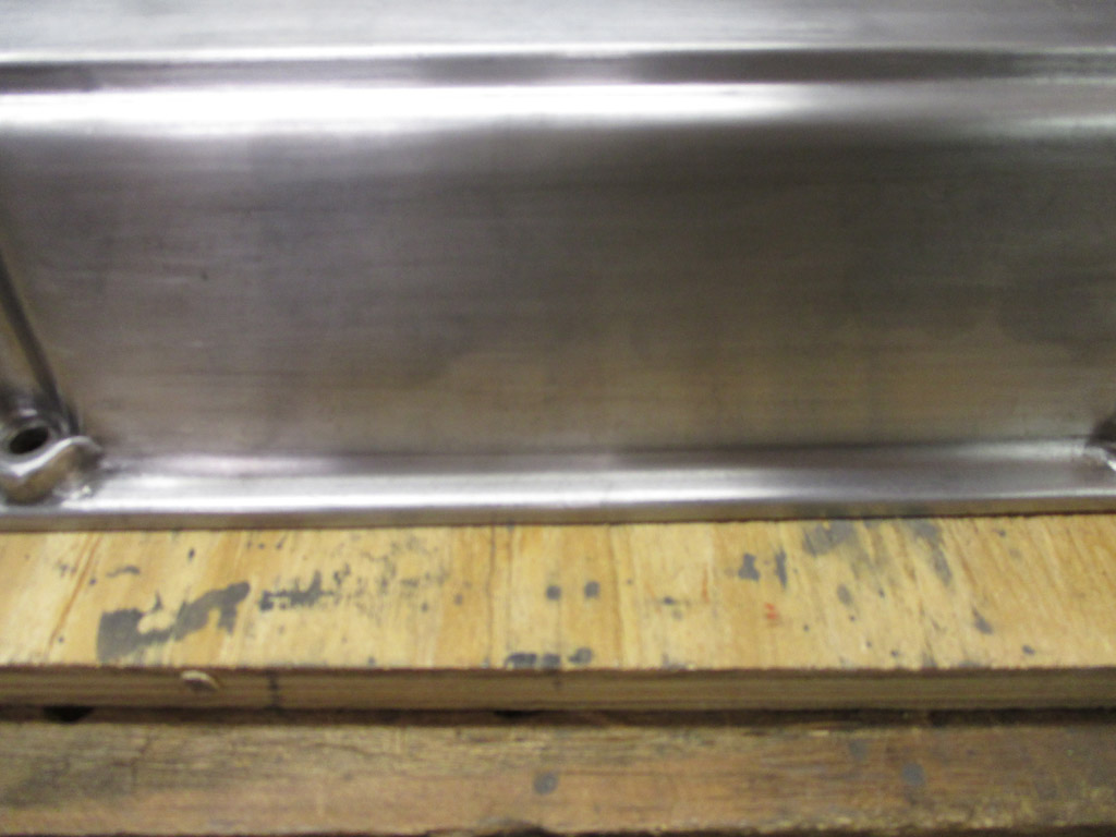
After the 600 grit, I moved up to 1500 and finally to 2000 grit sandpaper, each round of sanding removing the scratches left by the previous one. The finer the grit of paper, the higher the gloss of the aluminum.
I could probably call it good at the 2000 level, but I'm going all the way with some Mother's aluminum polish to cap off all my efforts. That'll give me a high gloss and hopefully keep the aluminum from oxidizing too quickly.
With all the vertical surfaces at the 2000 grit (wet/dry paper) level, the rather tedious job of working between the ribs was staring me in the face.
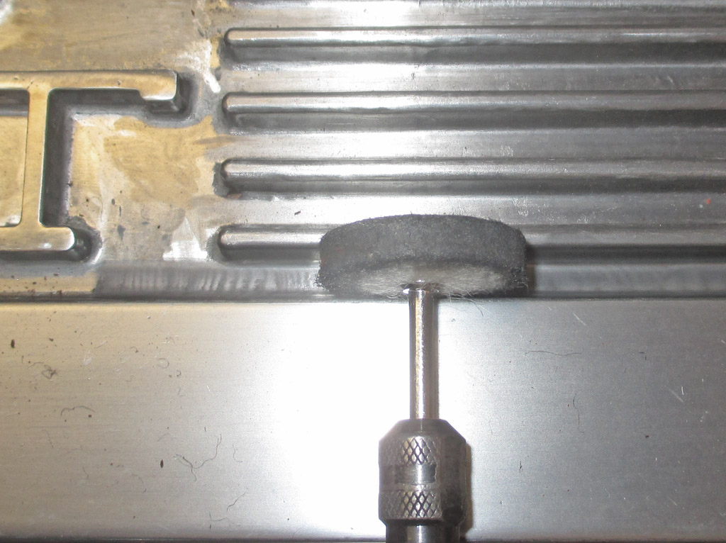
I did some research and discovered a whole world of jewelry polishing instruments. Hmmm. I found all sorts of shapes available in "diamond impregnated" silicone. These tools are specifically designed to polish metal no matter what the shape. Just the ticket for a project like this with all the little nooks and crannies needing attention. I need to get this area completed and masked off before polishing the sides with my air-polisher.
When I bought these valve covers, I thought I was saving money. If we're talking initial investment, mission accomplished. Highly polished aluminum valve covers ready-to-install were going for around $150 or so, even more if they were "RARE!" I don't think I was fully aware of what I was getting myself into. My initial objective was to just clean these up a bit, but it quickly exploded into a full-on restoration project. I have to install both rocker arm covers so I can install the plugs and wires and carburetor. And here I am piddling away hours and hours polishing aluminum. Clearly not my best decision.
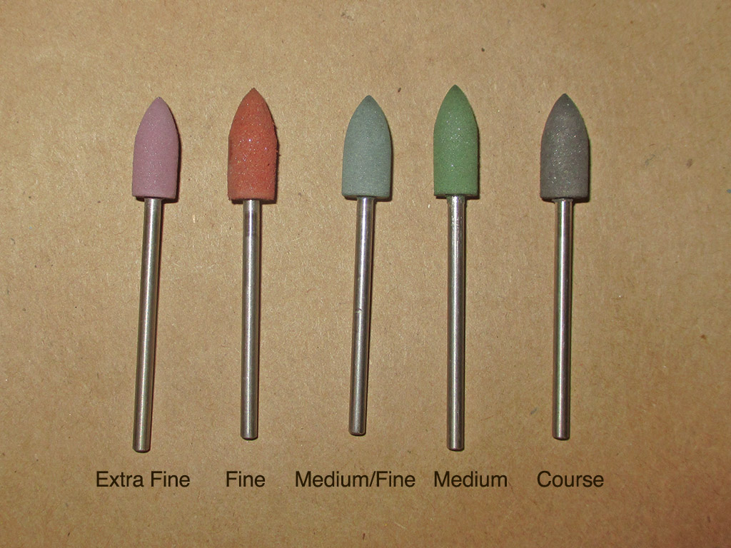
POLISHING POINTS
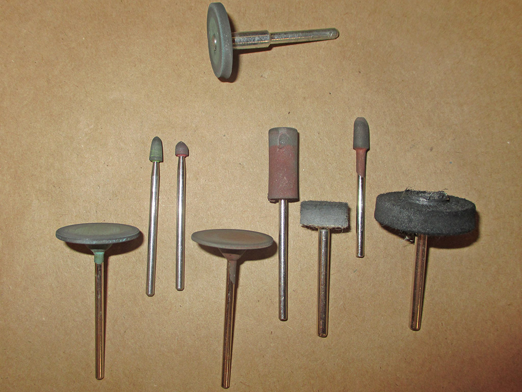
OTHER SHAPES USED
Time also figures into the parts procurement end of things. I placed one order and the polishing shapes would arrive. I'd use them up faster than anticipated and had to go back and order more and wait for delivery. In addition to the polishing shapes, I also ordered up some polishing felts for some of the hard-to-reach areas. I already had the standard Dremel small and large felt wheels, but needed more flexibility than those offered me.
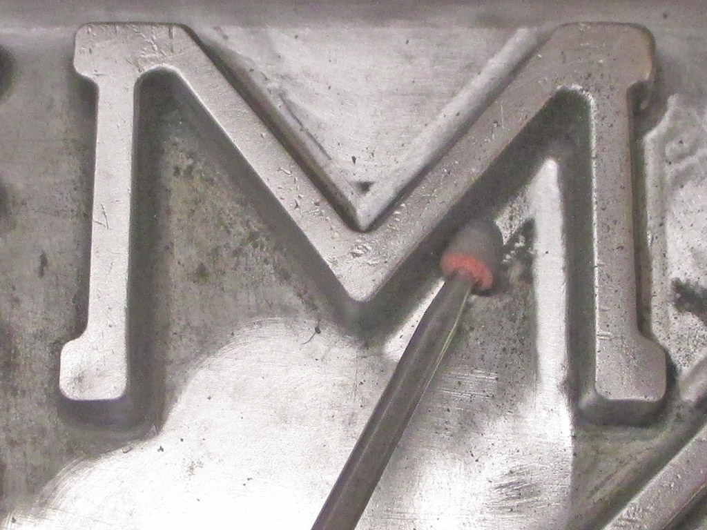
One of the available styles I found especially handy is called a "candle tip." They're perfect for getting into really tight spots like this. The downside of course is as you use them you eventually wear down the tip until the metal shaft is exposed. Then you have to stop to avoid damaging the surface you're restoring and reload with another tip. Always assuming of course, you have a replacement handy.
Clearly I have a problem. I just don't know when to quit. It's far too easy for me to get caught up in my own relentless perfectionism in a project like this... you reach a certain point and you're pretty much committed to seeing it through to the bitter end. I keep seeing one more imperfection and give in to the temptation to fix it too.
As work progressed I nixed the orange paint between the ribs plan. I've already fallen way behind where I thought I should be at this point in the assembly process. Masking, painting and all the rest is way too much futzing around considering I haven't even fired up the engine yet. I decided I would polish all the surfaces to the same gloss and call it done.
I tried using some of the Mother's aluminum polish in one test section I prepped with the polishing tips I got off the internet. This stuff brought up a shine that's almost equal to chrome! I set about using the polishing shapes to remove the weathered surface, following that process up with two felt wheels and some felt points I bought off the internet to get in and around the letters.
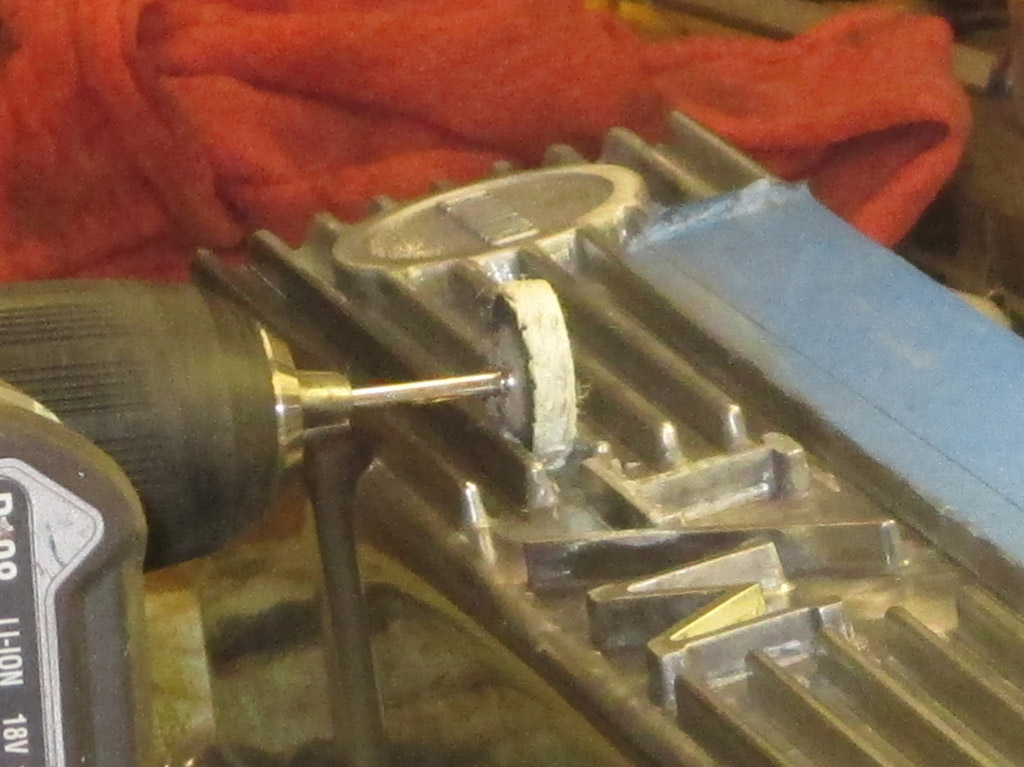
The Mother's aluminum polish is a great product, but it's thinner than the polishing compound you get in the Dremel kit. Even on the slowest speed my Dremel is capable of, I was slinging the polish all over the place. One way I coped with this issue was to use my variable speed drill instead. It's big and heavy, but I can start out slow and maintain a slower speed which worked best for me.
No matter how careful I was, I kept hitting the top of the cover with the Dremel or the drill chuck. So while I finished my work between the ribs, I put some masking tape over the area I wanted to protect. I finish things off by buffing the polish by hand with a microfiber cloth. Polish, Buff, Repeat.
I spent most of a Sunday morning finishing between the letters and the remaining ribs I started the previous weekend. Another rollicking 5 hours of unparalleled fun. I'm rapidly approaching the point where I just want this project to end. Each time I think I'm on the home stretch and will finish polishing and get back to assembling, I see scratches or a dull area and the job drags on. I think next time I'll pay more for something finished and ready to bolt on.
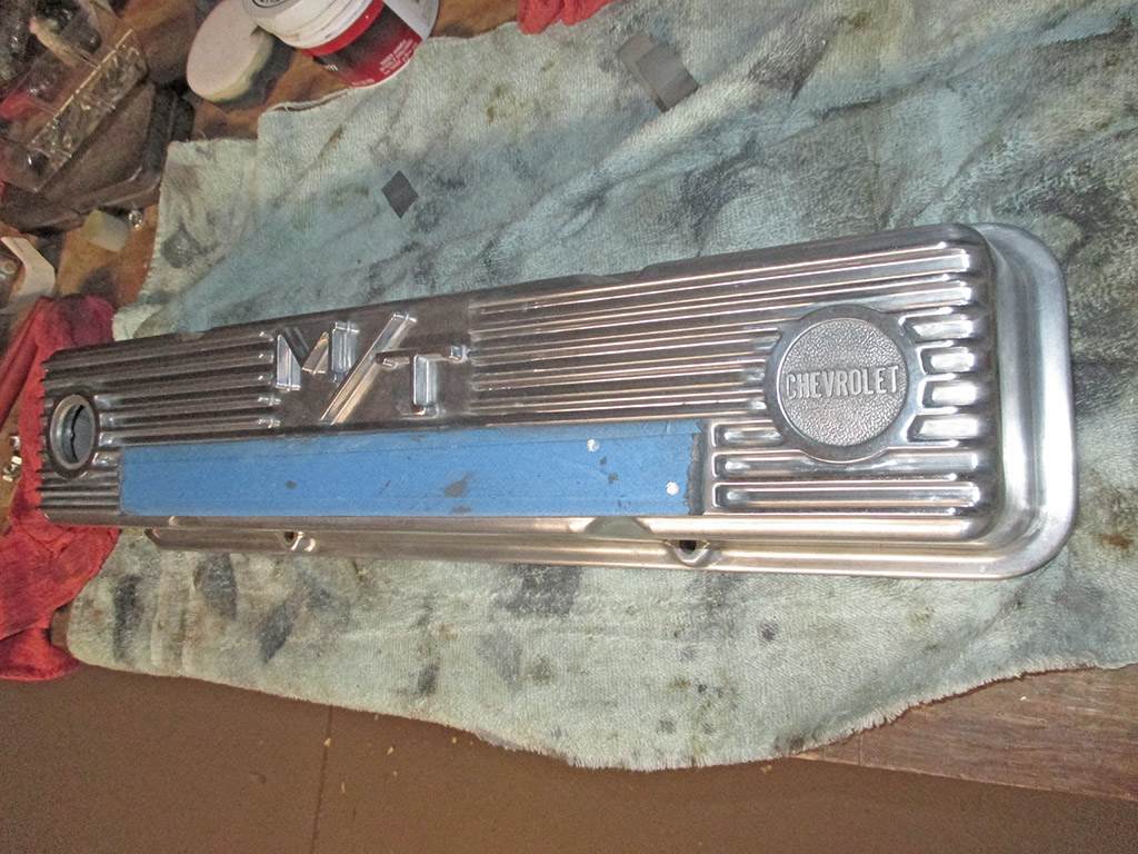
With the ribs finally finished, it was time to put a reverse spin on things and mask off the ribs. If I don't, I'll be slinging aluminum polish all over an area that took me forever to buff out. The shine at this point is strictly from the 2000 grit wet/dry sandpaper. Staying true to form, I found a few spots that needed touching up as I began polishing. One bad spot needed 600 grit, then 2000 grit, then I had to re-polish.
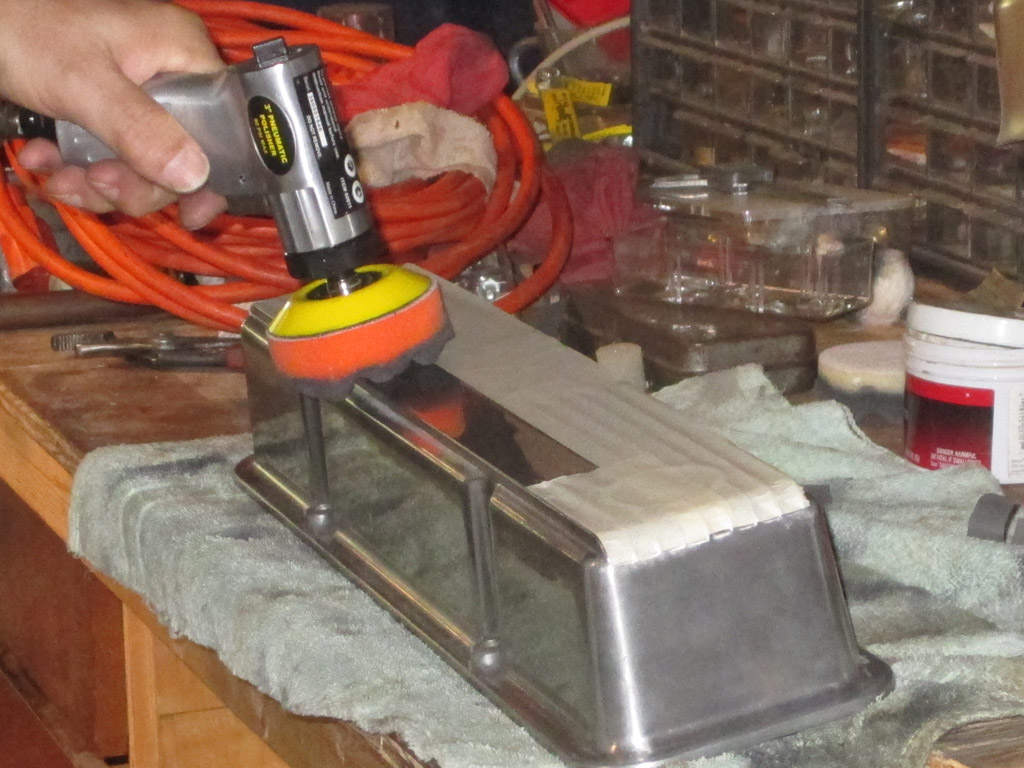
I used a wood craft stick (think popsicle stick) to apply the Mother's polish directly to the area I was working on. Then I picked up my air polisher and smeared the polish back and forth before pulling the trigger. This prevented most of the polish from being thrown off the rotating polishing pad. You need to be careful to not saturate the pad with the polish. When I started to see the pad buffing off the polish, I knew I needed to add another dab of polish.
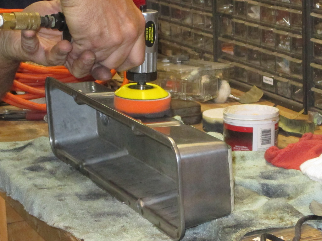
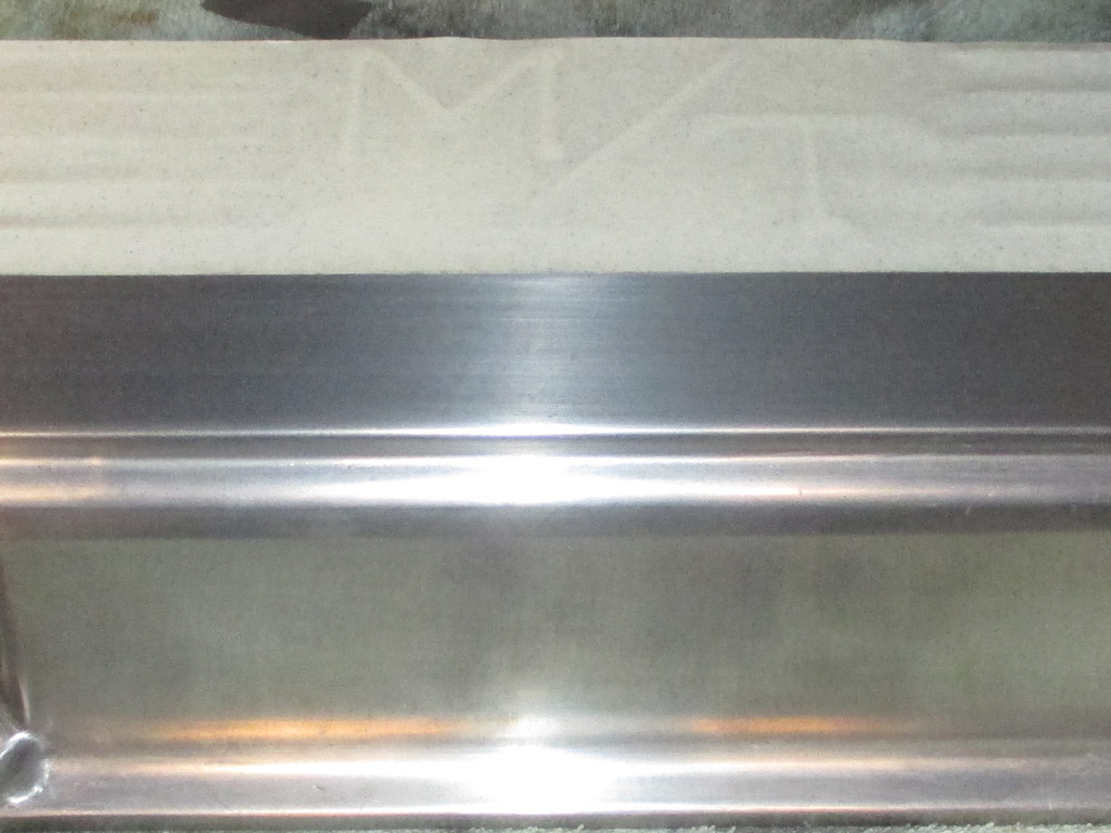
I laid a strip of 3/4 plywood on my bench and covered it with a shop towel (recycled terrycloth bath towel) to create a "stepped" surface upon which I could work without scratching the aluminum. The longer you work with this tool, the higher gloss you get and the fewer scratches you see in the surface. Once again it was a time consuming process that I hoped would pay off in the end. Polish, Buff, Repeat.
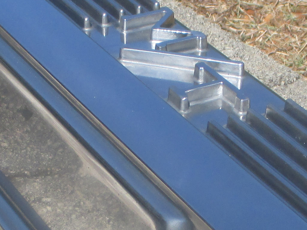
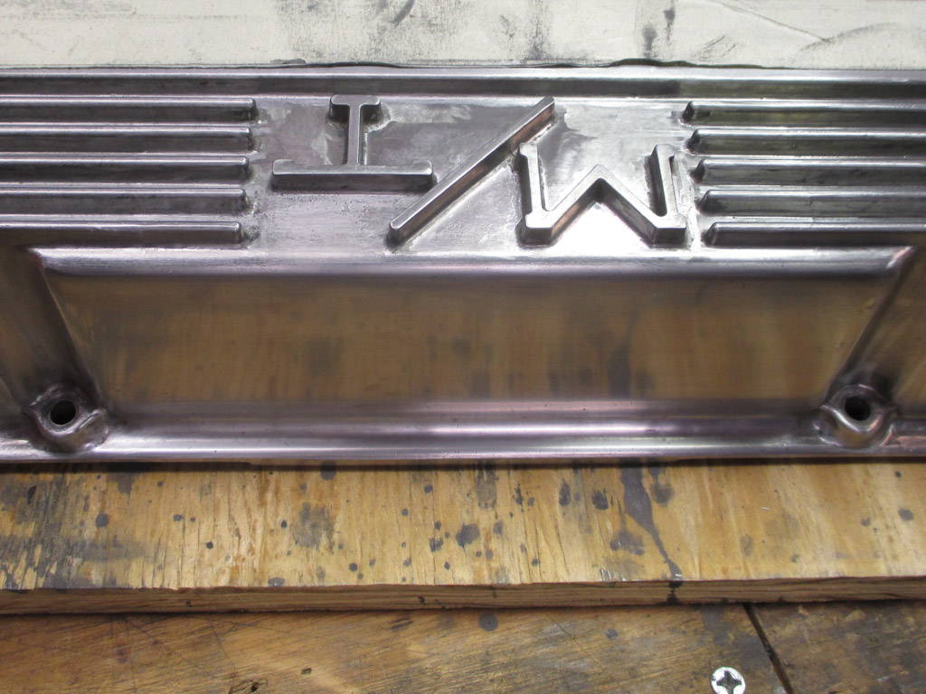
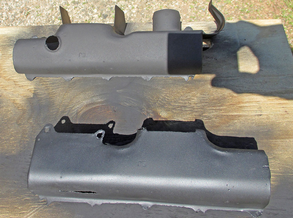
The Finished Product. After all the hours spent tunneling out of prison on this project, freedom was mine! I think the final results speak for themselves. Would I take this on again? I don't think so. Was it worth it? I think it was, because I now have some period correct dress up parts under my hood. It sure went a lot faster in my mind though.

Meanwhile...
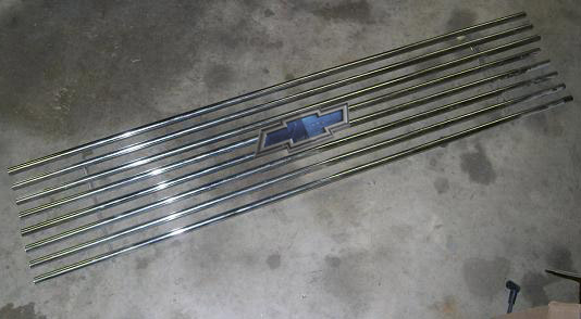
Although mine is a conversion (as opposed to scratch-built custom), van I still wanted to have the look and feel of the vans of the 1970's. This meant replacing the stock factory plastic grille with something more in tune with that era. To me, this meant obtaining a vintage tube grille. There are still a few sources for these, (round tube, square tube, even billet) but the prices are a bit steep.
I found what I was looking for on the bay of E and it included an original bow-tie emblem, which sealed the deal for me. I asked for measurements from the seller and they seemed close, so I pullet the trigger. The width at 50" was just about perfect, but the height of 10" just wasn't making it. I studied how the grille was made and soon formed a plan to modify it to fit. The cost was $30 bucks.

Vertical bracing is comprised of three 1/4" sections of channel material with holes spaced as needed. Since this unit was originally for a pickup, it was only 10" high. I attempted centering it in the van's grille opening, but it didn't look right.
Without access to the original tubing material, I couldn't just add in a couple of extra bars either. After much measuring, I determined the height for my new creation would be 12 inches. A trip to Lowe's netted me some new 1/4" aluminum channel. A little hacksaw work and I soon had three 12" high sections to work with. All I have to do is space the holes further apart and I'll have what I need. Each screw goes into a clip that slides along the length of each tube and the hole in the channel is bigger than the screw diameter for additional "wiggle" room.
My plan was fiendishly simple. I would start at each end using the original "channel-full-o-holes" as a template for the top and bottom holes of each vertical brace. This lets me mount the top and bottom bar of the newly spaced grille to check in the grille opening. If the top and bottom bar fits the opening I'll fill in the rest of the bars by dividing the remaining space by the number of bars I have left. Now let's see... where did I leave those HS Math skills?
MARKED

DRILLED
My initial reaction was to size each hole for the diameter of each screw. I quickly rejected that idea and decided to keep the holes larger than the screws as originally designed. This was obviously done to build in some "wiggle room" so you could make adjustments for the best fit. Since I don't have a jig for this thing for that kind of meticulous fit I decided to replicate the original design.
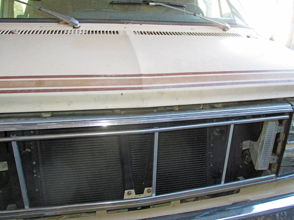
The first test fit of my creation. The OEM signal lights were mounted to the plastic grille. I took some Chevy Caprice signal lights, rotated them vertically and mounted them to the radiator support. The advantage to this approach is the OEM "quarter turn" socket fits these perfectly, so I can always change back to stock if I want and no wires were harmed during the swap. The downside is that the use of one lamp to illuminate such a wide housing gives an uneven look when lit. I may decide to switch to an LED setup at some point to remedy this.
I set the new assembly in the opening to get this shot, so it looks like there's a huge gap at the top and none at the bottom. When I held it evenly in the opening with both hands, it didn't look half bad. There's maybe a 1/4 inch gap on the top and bottom, which was what I was aiming for. The individual tubes have a slight V shape to match the opening, but the pickup opening must've been flatter since the tubes weren't quite bent enough. I lined up the existing bend in each tube with a vertical section of pipe and pulled carefully to increase the bend slightly. It took a gentle touch to bend it just enough without going too far.
Engine
When I bought the van it had a severe belt squeal coming from the alternator belt. The seller said he couldn't stop the squeal no matter how tight he made the alternator (which is a no-no, you'll kill the bearings in short order with this little band-aid), so this was at the top of my to-do list for reliability purposes, to say the least. Long story short... time to replace the alternator! I've never done this on a van before, but how hard could it possibly be?
Alternator Replacement
April 2013
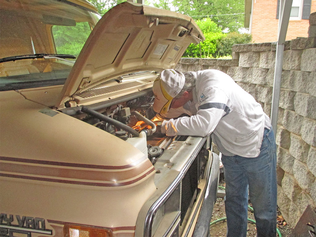
How hard indeed! What's that little saying about "famous last words?" Having never owned or worked on a van before, I greatly underestimated the talent of GM's engineering team to jam as much stuff as possible beneath the mail-slot-sized hood of this particular generation of van. All you have to do is tackle a project like this one to fully comprehend why labor costs here in the US (and in other parts of the globe as well I imagine), are through the roof. I had to dismantle a number of components just to uncover the blithering alternator. This was a real first. I figured I'd better document everything, just so I'd remember how I did it the next time something goes haywire on this thing!
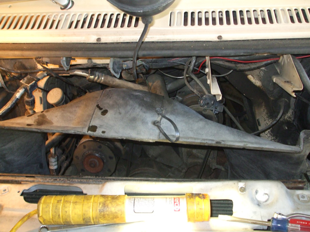
Seeing as how this wasn't my first rodeo (by a long shot), I broke out my tools and jumped right in with both feet. Usually in tight quarters you have to remove the shroud and fan, so I was already prepared for this part of the dance. But first, before anything else transpires, you have to remove the hood latch and set it off to the side. The cable for the hood release mechanism runs right over the top of the shroud (and there's no slack to move it without unbolting the latch), so it's the second thing I had to move out of the way.
The two very first things I had to remove (believe it or not), were the dipsticks for the oil and transmission fluid! The little finger hooks for each stuck out just far enough to snag the shroud, which was already up against the radiator. Click to enlarge and you'll see what I mean... this baby is stuffed tighter than a teenaged girls blue jeans!
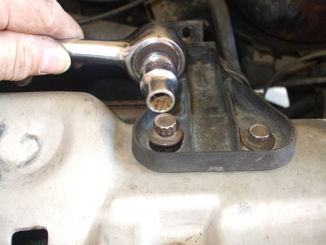
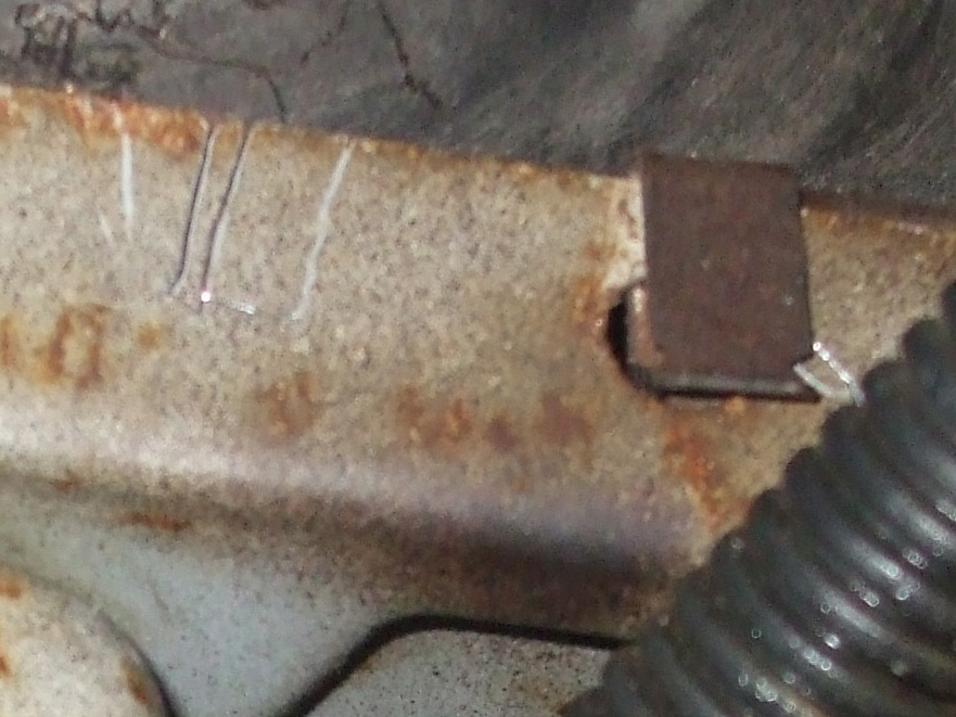
Okay... so now that the first two obstacles have been overcome, I can move on to the brackets that hold the shroud in place. That's when I ran into these babies. Were they afraid someone was going out stealing the radiators out of all their vans? I've never even seen such fasteners before, but as luck would have it, I was able to use a 12 point 7/16's socket which amazingly fit these weird looking bolts perfectly! Go figure. But once I had removed the two top brackets, how do I get the bottom edge of the shroud free? Turns out there are two little clips, (on on each lower corner) that the shroud clips into. A quick tug upwards and the shroud was finally free. Booyah! Not so fast there Chuck, she may be free, but we're not out of the woods yet!
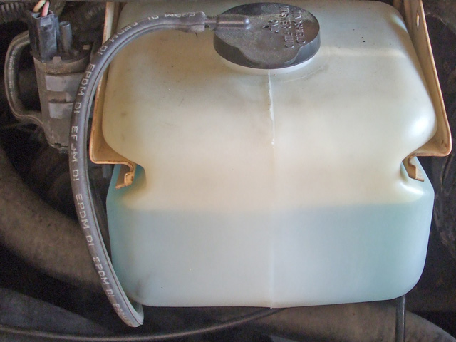
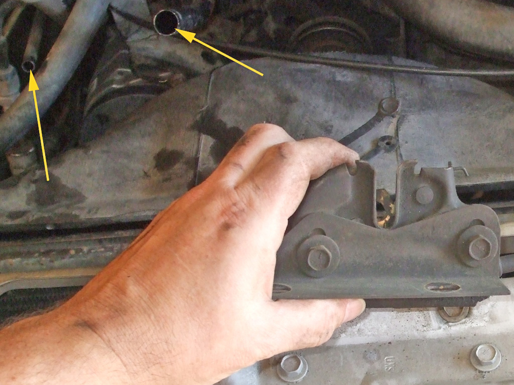
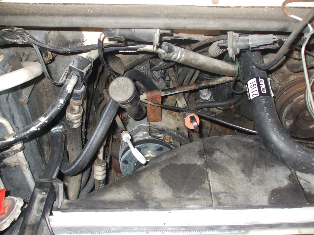
Hmm, now what have we here. Ah yes, the windshield washer bottle... and right up front and in your face too, just so you don't miss it or anything. I actually have to give a hat-tip to the engineers, this unit was clearly designed to be easily removed (disconnect the supply hose and it slides right out), but the bracket will need to be removed also. The small cylindrical object to the left of the bottle is the actual windshield washer pump, which conveniently slides up and out of two clips on the side of the bracket.
My celebratory mood was short lived once I realized I'd only achieved about 4-6 inches of free play in the shroud. It still wasn't going anyplace. I wasn't prepared to have to take out the windshield washer apparatus before doing so. At this phase of the game, the plastic bottle has already been removed and set off to the side, the next step is to go after the bracket so I have enough room to lift the shroud up and out of the way.
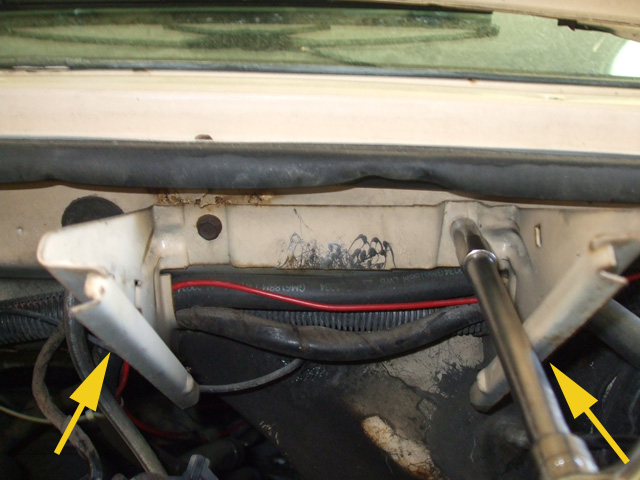
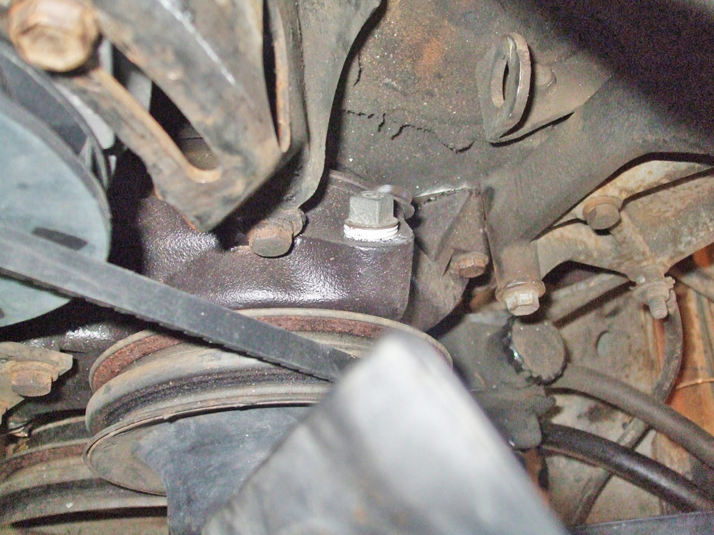
Here's a shot of the bracket. You better break out your metric wrenches when you get to this phase of the operation... 10mm to be exact. A long extension helps make the task a bit easier as well. The two yellow arrows? Now you didn't think GM would let you get by with just two bolts now did you? They went ahead and secured this baby with four, two you can see and the other two you have to dig for. Nice. One of them was still half covered in the factory undercoating just for that added bit of fun. And here I'd been congratulating myself on scoring a vehicle of such a vintage that I might find all SAE fasteners.
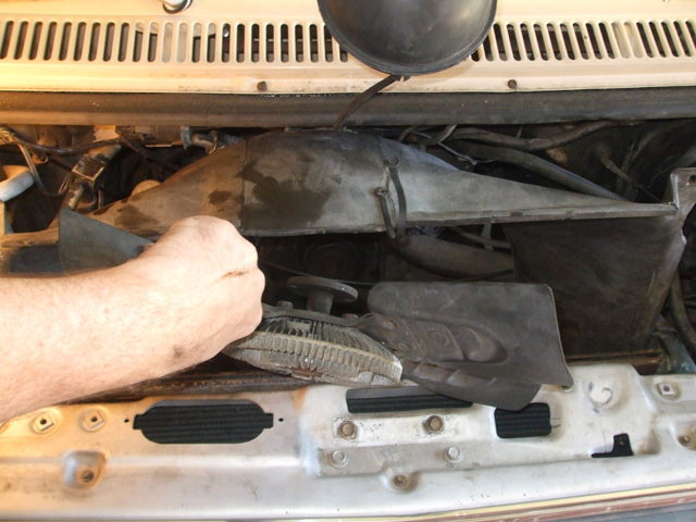
Finally! When I'm tinkering with vehicles that have a one piece shroud however, this is my modus operandi for gaining access to the front of the engine. It can be a little tricky to master this maneuver, but I've found it eliminates potential damage to the fan, shroud or radiator. What can I say... it works for me. At any rate, with all this "stuff" out of the way, I can finally access the faulty alternator and start the actual replacement process.
When I had to replace a bad water pump on my Monte, this is where I'd typically begin. Of course compared to the packaging of the van, the Monte is a cake-walk. It has only one piece of sheet metal filling the gap between the radiator support and the front bumper, and that's it. Then you simply jump in and remove the shroud. The Monte has a little better design (in my humble opinion), in that the shroud comes in two halves. I think with the water pump replacement on the Monte, I unbolted and simply removed the top half of the shroud to give me access to the fan and water pump. A totally different design of course, but it just goes to show the differences between two vehicles of the same brand.
Finally we're able to get down to brass tacks. We've all heard the credo that you can't judge a book by it's cover. While that very well may be true for reading material, when it comes to mechanical components, appearances are a key factor in diagnosing a problem. As soon as I saw the condition of the alternator, I knew it was destined for immediate replacement.
If I didn't know better (and who's to say I do), I'd be willing to bet that I'm looking at a genuine bonefide junkyard alternator. This looks for all the world as if it's been sitting in a wreck somewhere and the previous owner decided to take the cheap way out. Nice. I'm not putting him down for using junkyard parts mind you. Far from it. I'm a big believer in automotive recycling and have done a lot of it myself. The difference is, I'm mighty selective in what I procure from the local pick-a-part. Let's just say that electronic components are not something I source from a boneyard.
My more eagle-eyed readers may notice that I've already removed the bolts (1/2" top, 9/16's bottom), that serve as both anchor point and pivot point for this particular unit. I was so eager to get started (not to mention foolishly thinking I could thread this baby out of there with shroud/fan assemblies still in place), that I took this shot earlier in the proceedings. Nothing ventured, nothing gained I always say.
It's out! Seems almost anti-climactic after several hours of tool fetching, disassembling, cussing and skinned knuckles. Once I had the darned thing out where I could give it the old once over, another flaw became readily apparent. I'm not sure how much balance comes into play here, neither am I sure just how fast this baby spins at highway speeds. One thing I do know is that a brocken fan blade or two is just one more indictment for replacement.
The condition of the aluminum housing also leads me to believe that this unit was exposed to the weather at some point (the pitted surface indicative of exposure), lending further credence to my analysis. Yep, it's time to send this baby off to the big rebuilding plant somewhere out there (these days, probably China), in the automotive universe. That means it's time to saddle up and head over to the local auto parts store.
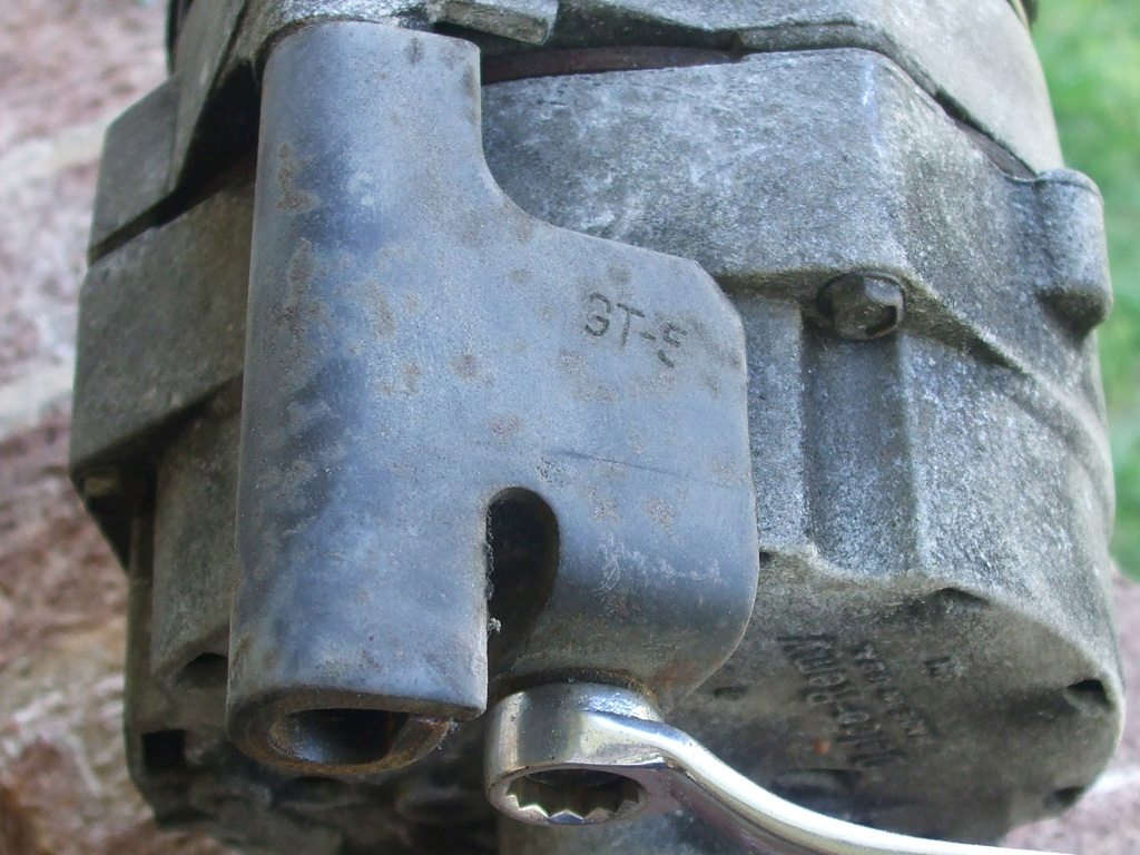
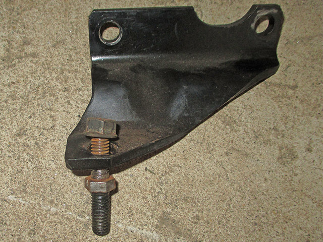
Way back when I first began tinkering with cars, I made a mistake (the first of many), when swapping parts across the auto parts counter. Seems I failed to realize that proprietary sub-components (like this bracket) are not included when you purchase a rebuilt (or new for that matter), part. If I recall correctly all it cost me back then was a return trip to the parts store and a rather sheepish explanation of what I thought of at the time as an amateurish mistake.
At the time though (already considering myself somewhat of a car expert), it was rather humbling to admit this in front of all the other guys (as each waited for a parts guy to fetch what they needed), in attendance. However, I'd worried needlessly (not knowing then this was probably a gear head rite of passage they'd all been through at some point), no one laughed and I was able to retrieve the necessary bracket with no hassle at all. The moral of the story is, any such bracketry should be considered to be made out of "unobtanium" and even the dealer will not have (nor be able to order for you), such a highly specialized item.
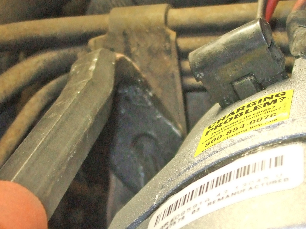
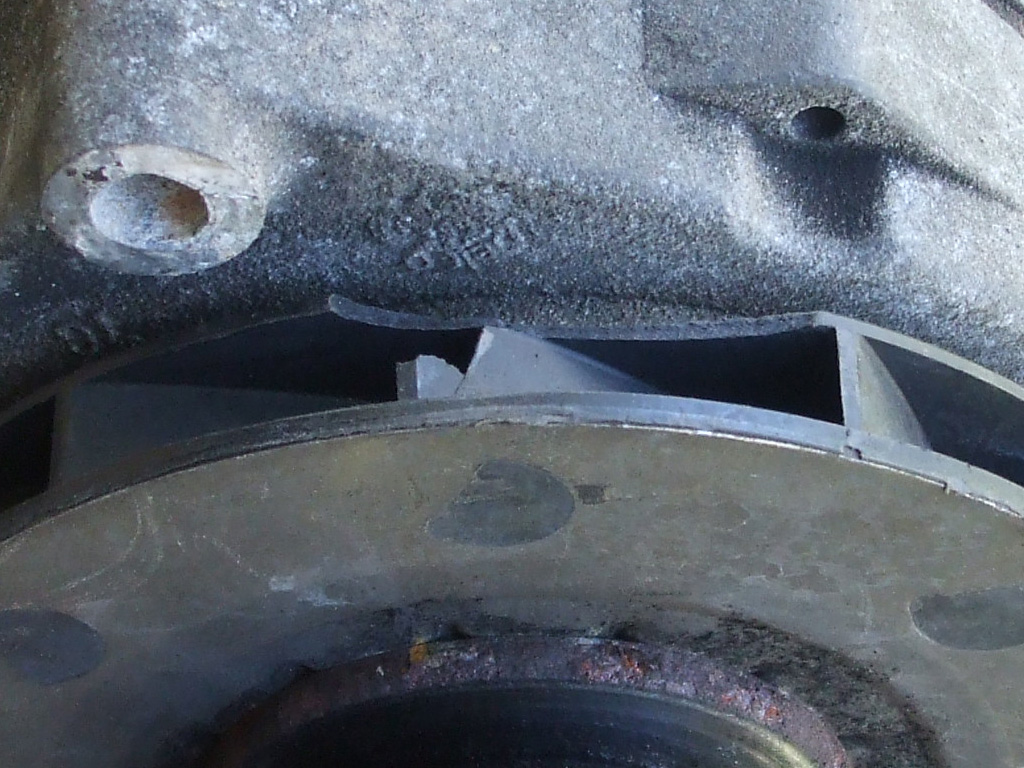
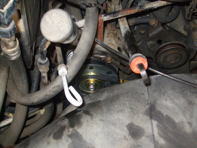
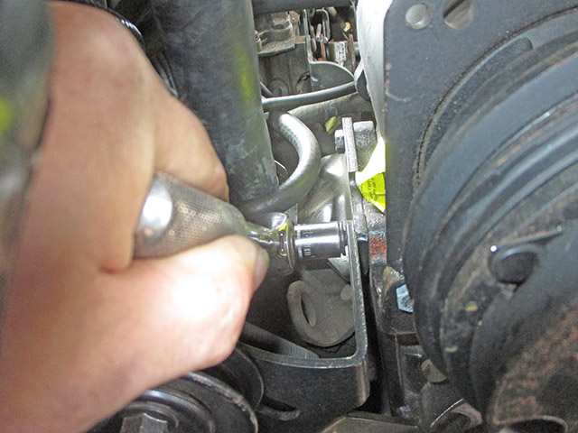
The first step (no pictures taken), was to re-attach the electrical connections. The plastic connector that attaches to the top of the unit was a greasy blob, so I spritzed it with some brake cleaner, wiped it off with a rag and it was good to go. The next step was to get both bolts started, the long lower bolt is usually the tricky one to get started. I could either get the bolt started without the bracket in place (unacceptable to Mr. Meticulous AKA me), bend the mounting bracket at the pivot point (too easy to skin my knuckles or perforate the radiator), so I had to come up with something else. This was my "something else."
I found that by pulling forward on the alternator, I could get the bracket about halfway into position. I noticed there was a step in the bracket, but my hammer was too big to fit into the tight space. So I rooted around in my toolbox and came up with a cat's paw. A few well placed, carefully executed taps and the bracket slid into place. Then it was simply a matter of tightening the belt (a quick spray of belt dressing before hand just for luck) to the proper tension.
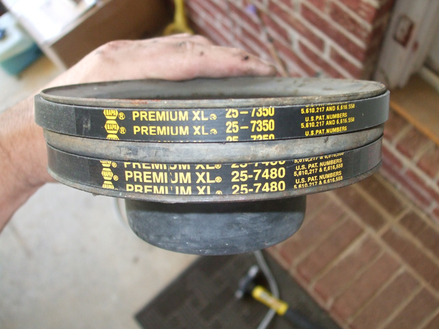
I've always been fascinated by what I find in cars I've purchased in the past. Turns out the van is actually better in this respect than all previous automotive purchases. The seller conveniently included lots of spare parts, including two brand new NAPA (not cheap those), brand belts that he hadn't gotten around to installing. Outstanding! Sure beats the rusty screwdrivers and busted sockets I've found in the past!
This picture actually serves two purposes. One, to illustrate the process I went through and two to document the parts numbers I'll need for future replacement. I've had good luck in the past with NAPA products. They may not be cheap, but considering how I plan on using this vehicle, I want quality replacement parts. The parts are branded as NAPA, but the Gates company actually manufactures their belts and hoses. You absolutely cannot go wrong using a Gates belt! For the record, the 25-7480 is the alternator belt.
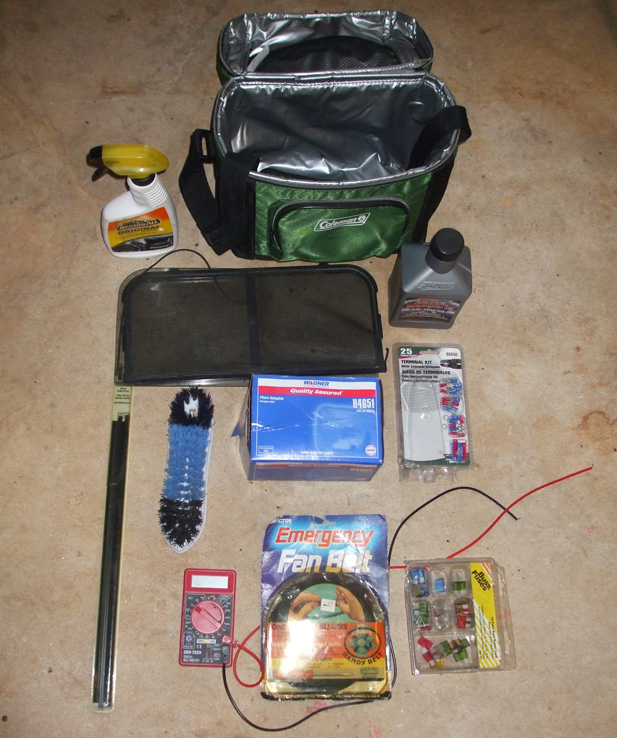
If we're going to discuss the spare parts that came with the van, I guess I should clarify that statement a bit. I got more than spare parts for my $1,000.00 (adjusted, more like $950) when you take into account all this other "stuff." Those NAPA fan belts? $30 bucks. The Coleman soft side 9 can cooler? $12. The Wagner headlight... $6.00. Armor-All ain't exactly cheap either, (although the Harbor Freight multimeter certainly is), so I my mind, I've essentially got a $950 van.
The wiper blades (brand new, sealed, made in USA) will be installed shortly. The Mr. Clean scrubbing brush? Already pressed into service cleaning some stains out of the carpeting. At some point in it's life, one of the van's vertical windows was replaced and the smaller window and screen were also included in this mini treasure trove. This is all useful stuff that I am either using or plan on using shortly; like I said before, sure beats finding a rusty screwdriver in the trunk.
At the onset of this farce, I'd been thinking I'd be finished in a couple of hours, since this was a job I'd done many times before. What I wasn't prepared for was the level of disassembly required before the actual remove/replace opperation could begin. However all things being equal, it wasn't a terrible operation and the beautiful spring day was put to good use. I test fired the van after the install and she was charging just fine, in fact the gauge began to drop off after several minutes indicating the alternator (and built in voltage regulator) is functioning as it should. One last thing, no more belt squeal... none! I call this repair session a success.
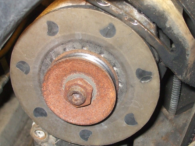
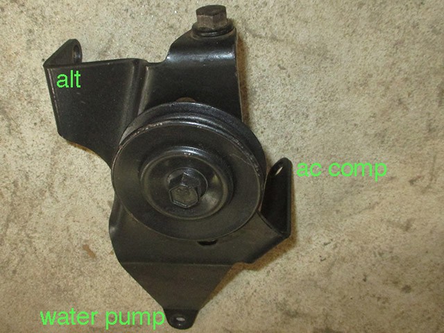
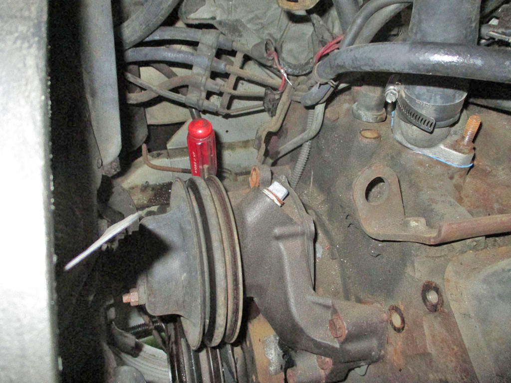
The idler pulley seen in this shot is for the air conditioning compressor, which will also require replacement. That day is still off in the future, so I removed the ratty old belt that was there for fear it might break at some point and cause headaches I don't need. Actually, my plan is to convert the system over to the modern (and much cheaper) R-134A refrigerant. Not sure what that will entail but when I tackle that little chore, I'll be sure to document the process on this page. The end.
September 2013
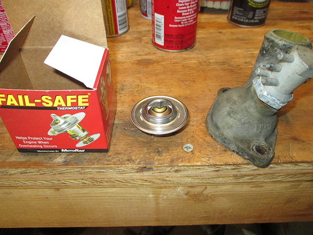
So here I am in the midst of finishing my body/roof modifications in the hopes of getting to the upcoming Great Southern Van Run and I've completely neglected something important. The cooling system was giving me issues so I bought a new hi-flow water pump, new radiator (old one too far gone to fix) and a new thermostat as icing on the cake. The new parts have been gathering dust sitting on a shelf for months and now need to be installed ASAP.
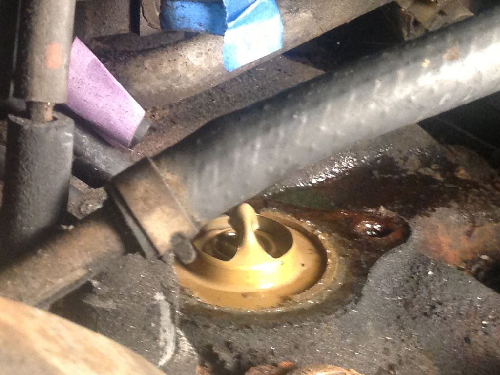
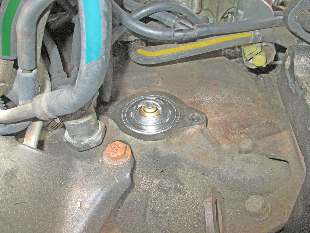
Sunday I moved under the hood to remove the water pump. With that out of the way, I turned my attention to replacing the thermostat. With the temperature needle barely budging off the Cold mark, I had suspicions that there was no thermostat at all in an attempt to get by with a partially blocked cooling system. Imagine my surprise to find a thermostat sitting right where it belonged.
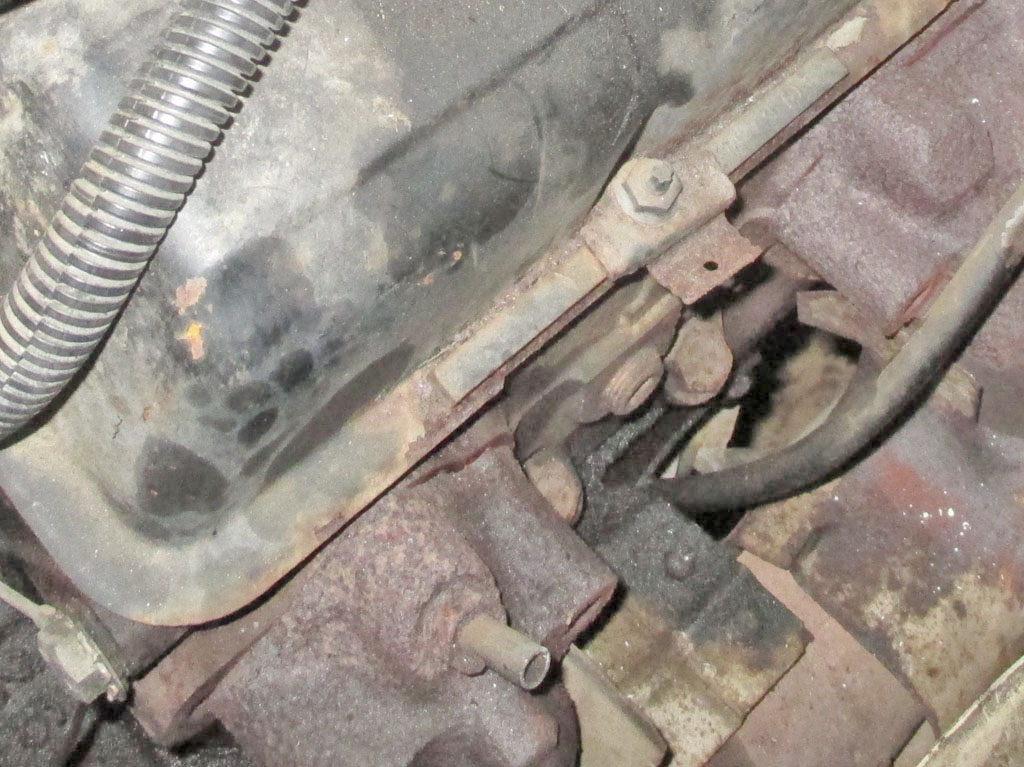
With barely enough room to get a deep socket on the left thermostat housing bolt, I tried to be careful of the ported vacuum switch nearby. I needed a leverage bar to break the bolt loose and broke off all four of the switch's plastic nipples in the process.
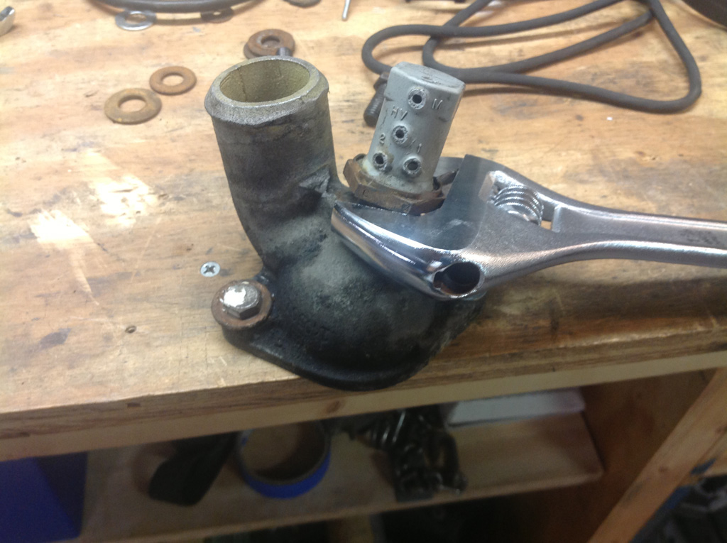
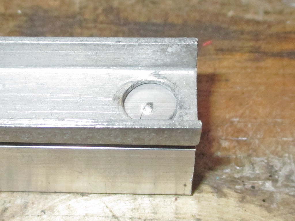
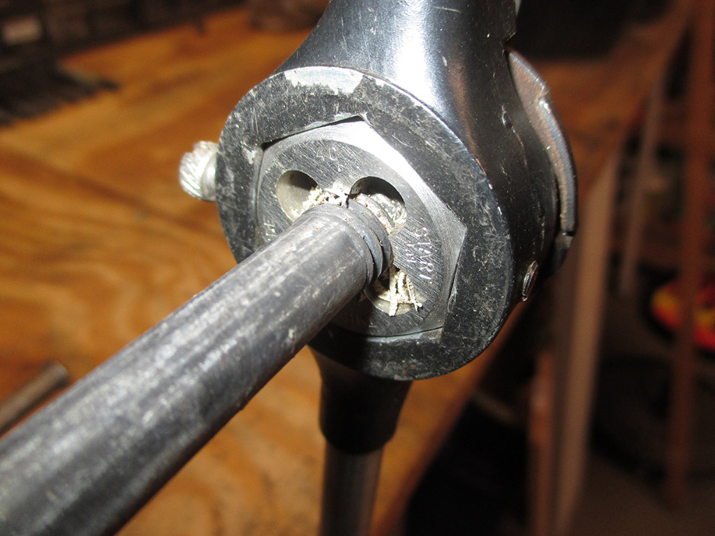
With the thermostat housing finally extracted I was left with the issue of holding the damned thing while I unscrewed the busted vacuum switch. I tried C-clamping it to the edge of my bench, but the clamps couldn't hold it. I built my workbench with an overhanging front lip for just this purpose, so I grabbed my drill and mounted the thermostat to the workbench with a couple of nuts and bolts. Now I had a good grip on the housing.
Next was a wrench large enough to fit the nut on the base of the switch. The only way I could get the switch to budge was to put my shoulder on the wrench and lean all 200 some odd pounds of owner against it. To my great relief, it broke loose without actually breaking anything else. Now all I had to do was find a ported vacuum switch for a nearly 30 year old van. Vacuum leaks wreak havoc on smog motors, so I got cleaned up hopped in my truck and went off in search of a new switch.
Amazingly, my local O'Reilly's found one in their store one town over and could have it delivered Monday morning. I needed it now. I figure I lost about an hour both ways (not to mention $32.99 on the switch), but I was still able to press on with the project at hand.
If there's one thing I'm grateful for it's the decision someone made to stamp the part number into the top of this ported vacuum switch. I stopped at Advance Auto first but all they could come up with was an electrical switch. They listed a vacuum switch, but with no picture to go by I wasn't going to order it and have it be the wrong item, so I went next door to O'Reilly's.
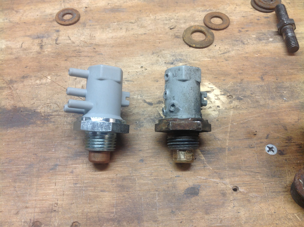
NEW VS. OLD
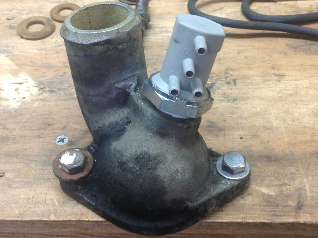
INSTALLED
So, I wrapped some teflon tape around the threads and carefully installed the new switch. I stopped when I had the nipples pointing rearward so I would not run into this situation in the future. I probably could've made like the HULK and gotten maybe another 3/4's of a turn, but that would place the ports right next to the bolt again and I did not want to re-create such bad placement. It's tight... just not super-duper tight like the old one. I destroyed an aluminum intake once by over tightening a fitting, so I err on the conservative side now.
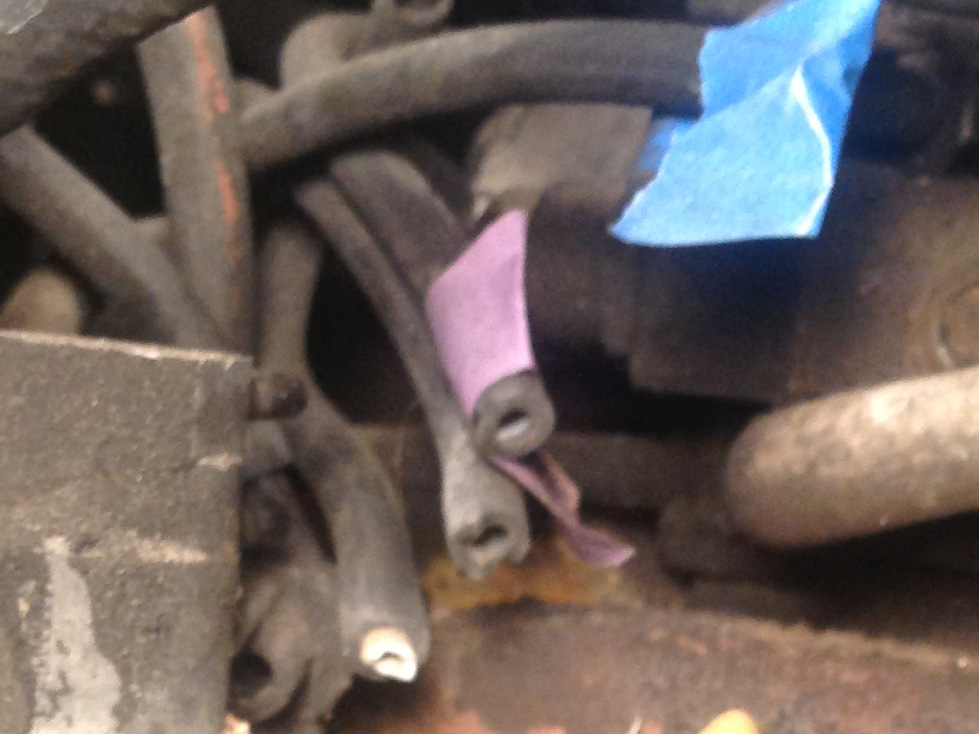
My feeble attempt to ensure proper hose replacement. Blue tape on the top hose, purple tape on the middle hose and a chalk stripe on the bottom, leaving the only remaining hose to feed port 4 on the switch. Only a couple of things wrong with my brilliant little plan.
First, through all my maneuvering of the housing (not to mention tightening of same), the tape came off. With no other choice, I used "hose memory" (where years of under hood life have pretty much bent them into a permanent shape) to hook each hose up to what I sincerely hope is the proper port.
In the process, vacuum hose number 4... well I don't know what the hell happened really... the damned thing was just... gone! I felt around as best I could (erroneously sticking my fingers into a defunct mouse nest in the process), but came up empty, so now I'll have a vacuum leak to contend with. Wonderful.
I would like to eventually replace all the vacuum hoses as cheap insurance, but I didn't need another fight at this point. It was getting late, I was tired, hungry, filthy and at every turn something decided to throw a roadblock in my path. The busted switch, a bolt that refused to go back in the hole I removed it from (despite "alignment confirmation" with a Phillips screwdriver), a radiator shroud clip in the wrong place and a hose that simply vanished into thin air... this process has really tested my skills and patience.
The driver's side rubber block the radiator sits on had to be trimmed for the shroud clip to slide into position. I don't know why. I didn't move the rubber block, it only mounts one way. The clip can only go in one position and suddenly it interfered with the rubber block. So I removed the fan, the shroud and both upper radiator brackets to give me enough room to remove the rubber block from beneath the rad. Then I took my Dremel to it.
Burning rubber (and later sparks as I cut into the metal reinforcing tab), filled my workshop with a malevolent cloud of smoke (causing me to plug in a small desk fan to blow the fumes away from my face), in the hopes of gaining enough clearance to slide the shroud clip into position. Took me two tries (killing an hour in the process), but I eventually got everything to fit. Then it was time to pull both dipsticks and carefully thread the shroud back into position (for about the 6th time, best not to discuss the upside-down attempt) doing my best not to ding up the radiator (any worse than I already have), and then leaving just enough room for it, feed the fan between the radiator/shroud gap and set it on one of the water pump studs. Makes tying your shoes while simultaneously falling off a 40 story building seem like childsplay in comparison.
It's hard to believe something so small and inconsequential could be so vexing. Part of the problem was time. Between the time I pulled the radiator and shroud and the time I reassembled everything, 6 months had gone by. Add to that the fact that one clip had come loose of the shroud and where I thought it should mount was wrong.
Not content with merely bolloxing up one side, once I had the clip installed (incorrectly by mistake), I then duplicated the error on the opposite side, which had previously been correct. Finally I crawled under the van to have a look-see and there were marks where the clip had been. As soon as I re-installed both clips correctly, I was able to get the shroud to finally line up.
All told, I pissed away about an hour and a half chasing my tail with this little issue. Unbelievable. Oh, that whole business of trimming the rubber radiator support cup... totally unnecessary of course.
While it's hard to see with most of the pulleys and brackets back in place the water pump is a brand new high-flow unit from Summit Racing. I also installed a new high-flow thermostat to go along with this little upgrade.
So, I finally got everything back together around 8pm that evening. New thermostat, new ported vacuum switch, new heater hoses, new radiator hoses, new water pump and a new radiator. So, needless to say, the cooling system should now be in tip top shape for some time to come.
November 2016
I was on my way home from work in late October, sitting at a traffic light when I noticed the temperature gauge. It was past the 3/4 mark and rising. I pulled into a defunct grocery store parking lot and shut it down. There was no trail into the lot, no pin holes in any hoses, water pump wasn't leaking, no drips anywhere. I refilled the overflow jug (using the "emergency" gallon of antifreeze I always carry) keeping it topped off until it was full again. Once it had cooled off I fired it up, cranked up the heater full blast and made a run for home. Pulled in my driveway just as the gauge began climbing again.
Since the thermostat is the easiest (relatively speaking) thing to replace, I broke out the wrenches and got to work. Most of the work involves getting stuff out of the way so I can actually get to the thermostat housing. Several vacuum hoses needed to be moved out of the way as well as several brackets.
First Steps
Step 1
Step 2
Step 3
Step 4
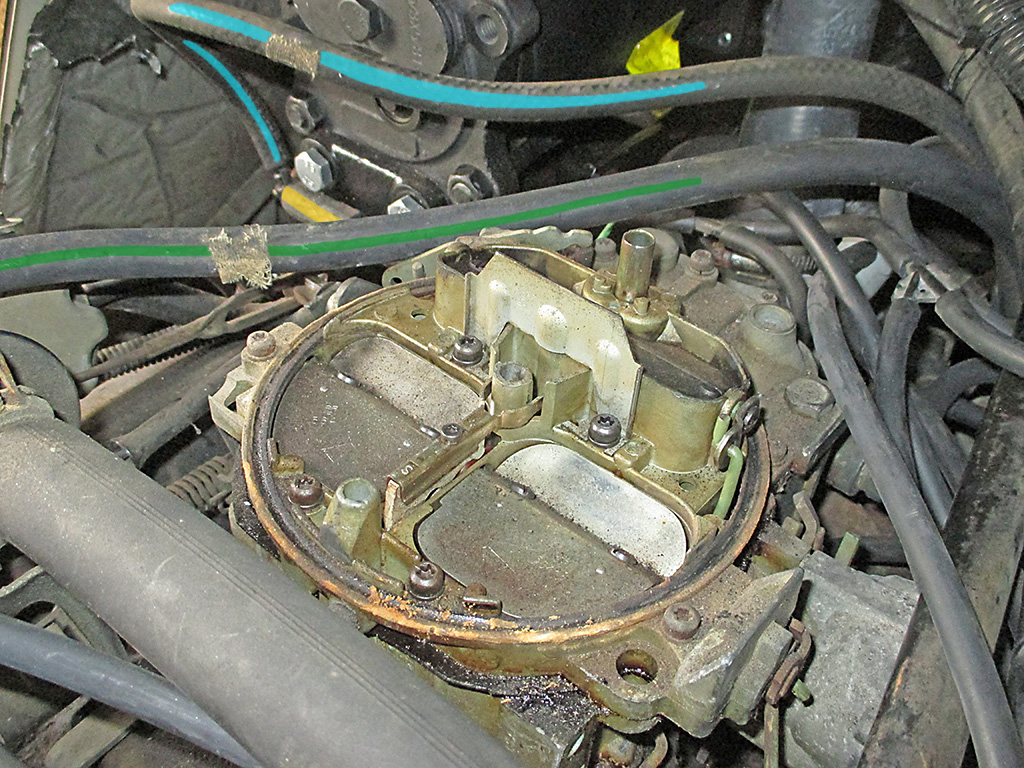
With the new Fail Safe thermostat in place, I attempted to start my van. I say attempted because it took forever to start and once it did it was shaking and rocking back and forth like some kind of deranged top fuel dragster. It sounded like it was running on about 5 cylinders or so, would not rev and quit after about 45 seconds with a snort back through the carb. Wonderful.
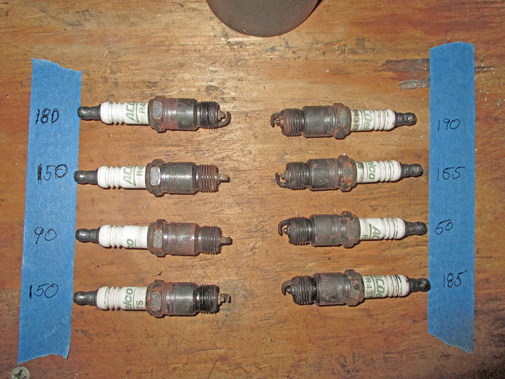
When I parked the van it was running nice and smooth like it always had. The only issue was that the engine was running hot and the coolant was disappearing. A few folks suggested I conduct a compression test.
The compression test results were quite sobering and left me with no choice other than to pull the heads off the mighty crippled 305. It took me a couple of weeks to absorb this rather depressing news and get motivated again.
Basically, I have to undo everything I've done up to this point. There's an exciting bit of news. New A/C compressor - off, newly rebuilt carburetor - off, alternator and PS pump (including their brackets), all removed.
I had to pull the compressor idler pulley adjusting bracket to gain access to the compressor support bracket. Then I pulled the compressor support bracket. I'm getting pretty good at this. Of course, I did all this back when I first bought my van, in an attempt to head off cooling issues. Yeah... how about that.
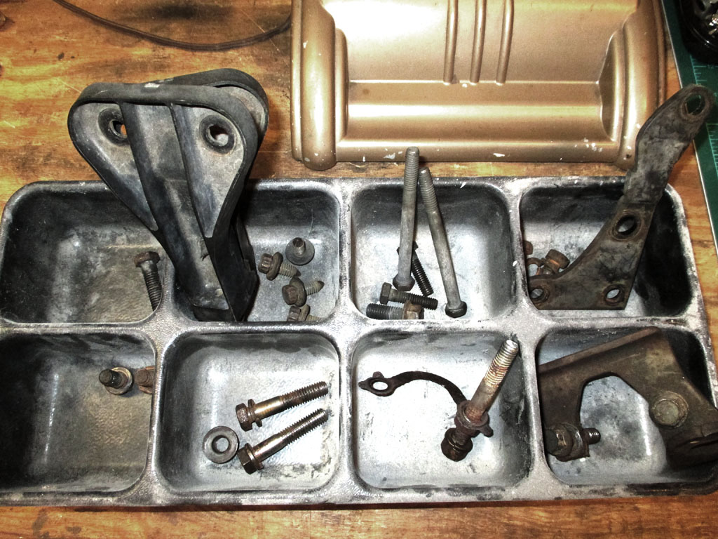
I had a few drawer organizers laying around doing nothing, so I put them to work. Between tearing the engine down, evaluating what's wrong and possibly sending the heads to a machine shop, there's no telling how long these parts will be sitting around so hopefully keeping them together will help the old memory.
For the bigger stuff, I've got a box of zip lock baggies and some sharpie markers too, but this is working for me at this stage of the operation.
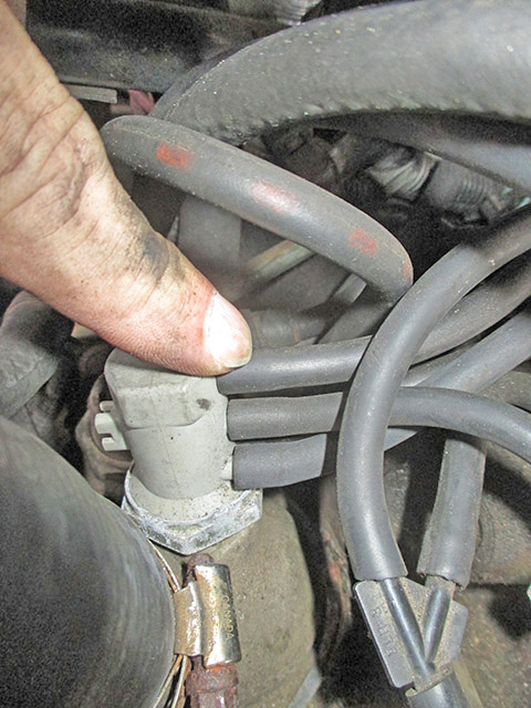
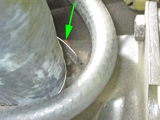
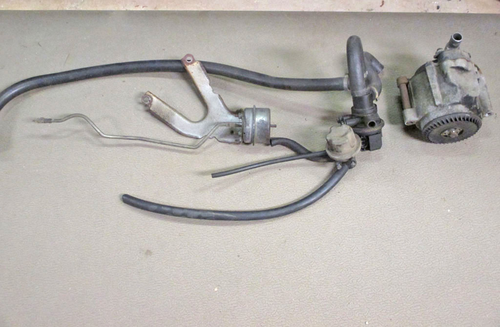
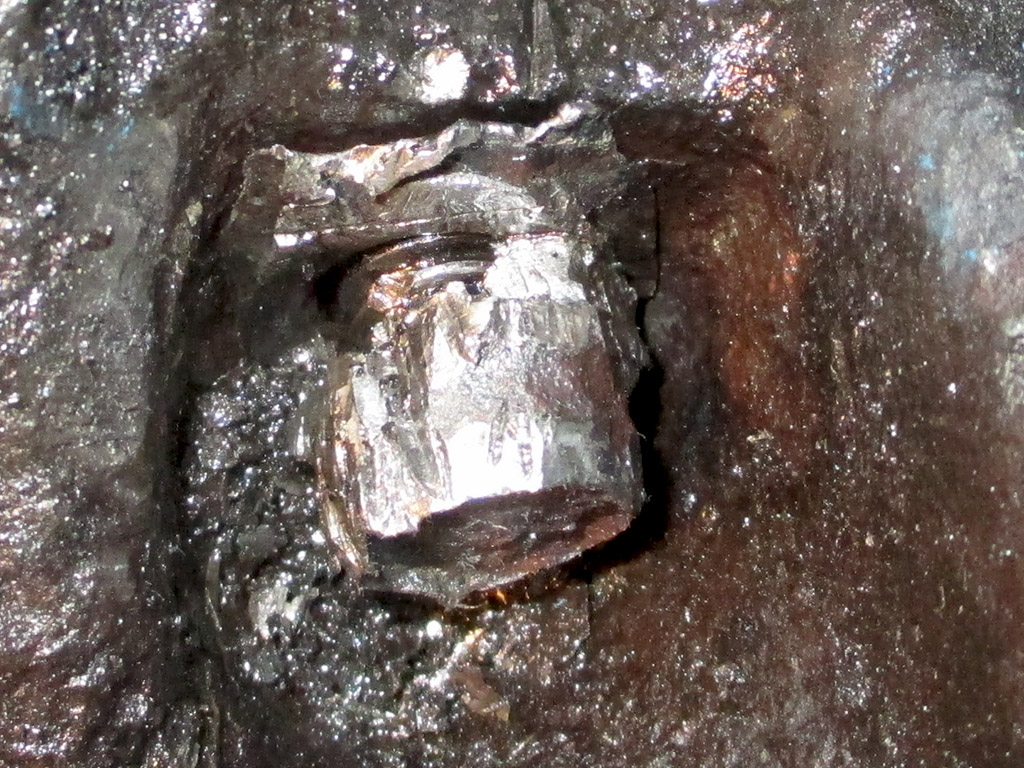
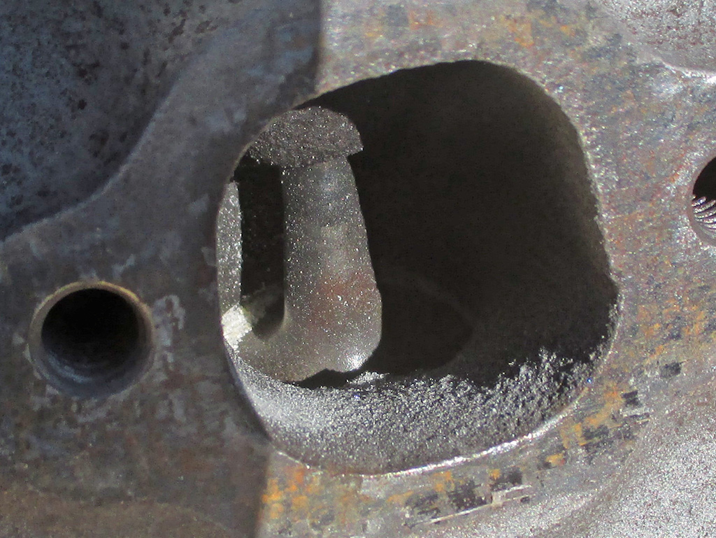
This is a TVS (thermal vacuum switch). It's purpose is to supply manifold vacuum to the EFE (early fuel evaporation) valve, closing it when the engine is cold, diverting exhaust gasses under the intake manifold. When the engine warms up, the vacuum to the valve is stopped, and all exhaust gasses exit through the exhaust system. The nipple of the valve on the exhaust manifold had rusted to the extent that it created a vacuum leak. I blocked off the hose with a screw to eliminate the leak.
This TVS also supplied vacuum to the distributor through a distributor delay valve, which was missing when I bought the van. It also supplied vacuum to a diverter valve associated with the A.I.R. pump. It then branched off to the temperature sensor in the air cleaner which controlled the damper door in the air cleaner snorkel to admit hot air from the heat stove on the exhaust manifold. Damn! Since everything it controlled has been eliminated (I'm using a later model air cleaner that relies on a bimetallic spring instead of vacuum), the TVS itself will be eliminated as well.
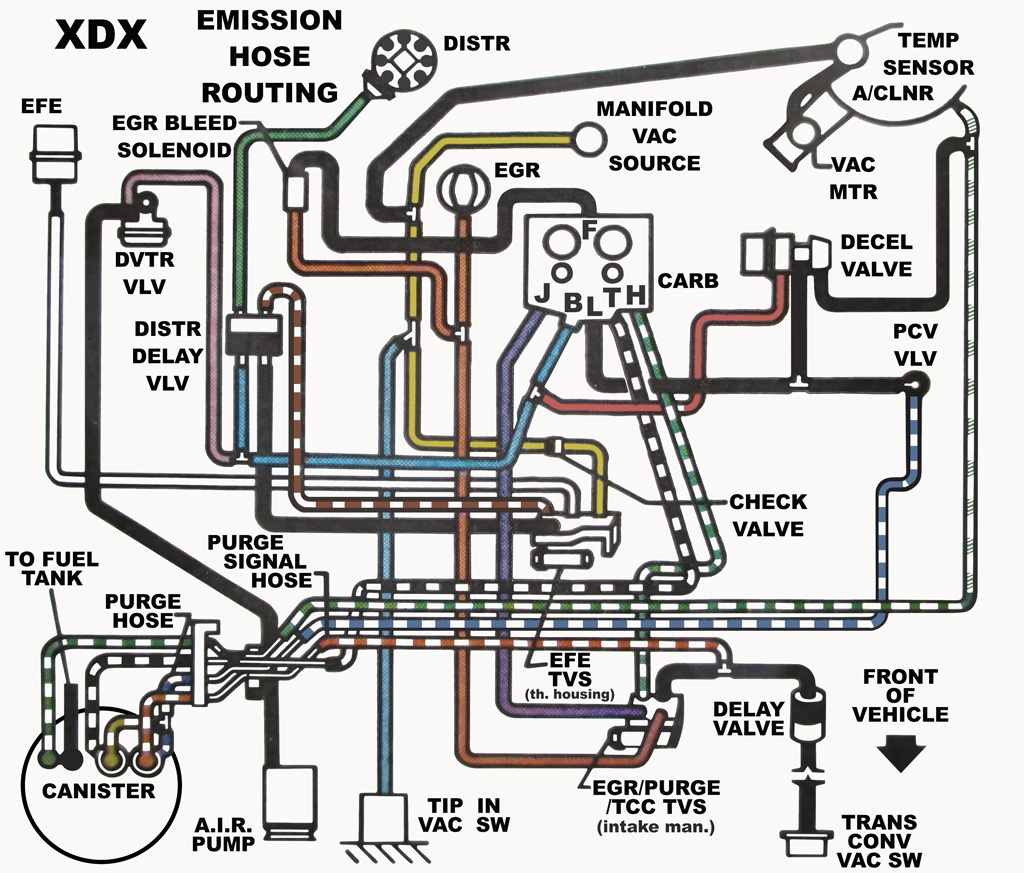
This is an "enhanced" version of the under hood decal that came with the van from the factory. Although the van carries evidence of a front-end collision at some point in its history, the hood (and thus the decal) appears original. Of course by the time I bought it previous owners had made some modifications to what is spelled out in the diagram, but it's a start. A reference I posted should someone else find it useful.
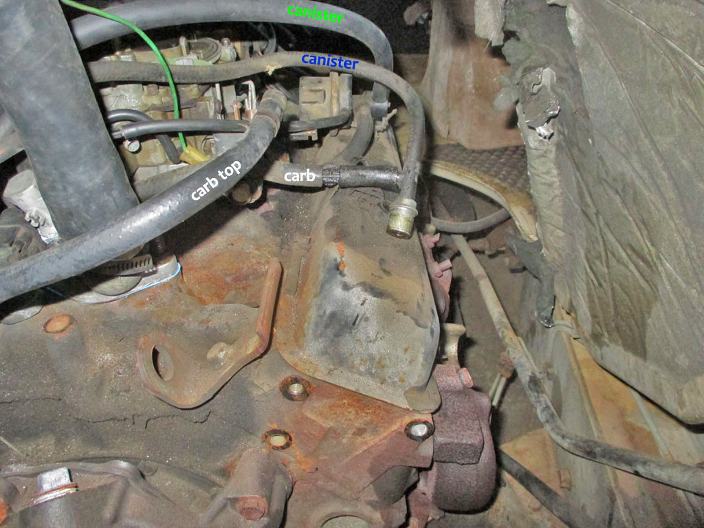
A diagram is one thing. A real-world look at the hose routing is something else entirely. I Photoshopped in the colors from the chart as a reference. Many of the vacuum hoses will be eliminated, but some (such as the charcoal canister hoses) I'd like to keep. My current thinking is along the lines of it works, so why eliminate it. Sure, I'm making improvements/modifications, but the lines already run from the tank to the engine compartment. That would mean removing the lines or capping them (rendering the OEM system inert) and going to a vented gas cap.
FRONT
REAR
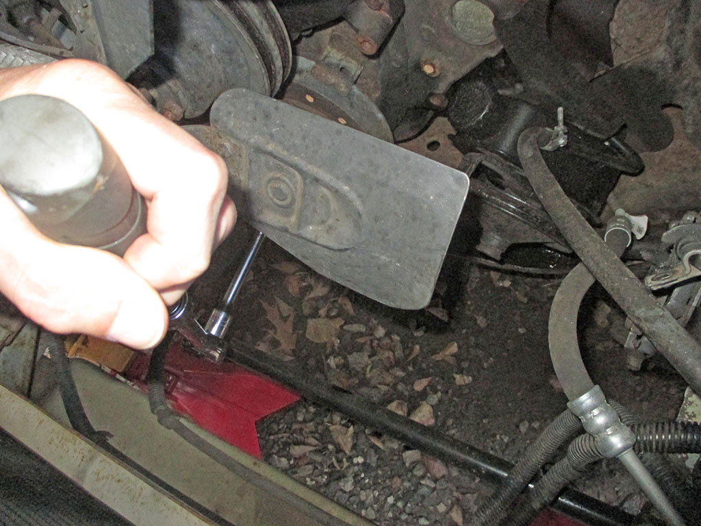
More reference shots designed to jog my feeble old memory. I placed a moving blanket in the middle of the van to store all these parts. The compressor, alternator and an assortment of brackets will live here for the duration. The screwdriver was used to let air in so the antifreeze could drain from the lower water pump outlet. This will hopefully take the level down to below the intake coolant passages.
COMPRESSOR OUT
ALTERNATOR OUT
Although the compressor and alternator hardware came off with relative ease, the same could not be said of the exhaust manifold bolts. I hosed them down with liberal amounts of PB Blaster and then began to tease them out. Tighten them a bit, loosen them a bit, back and forth until the bolt could be removed. Due to close quarters only a 3/8 ratchet would fit into the available space. In the end, only one bolt broke off in the head.

I made a few decisions on the fly at this point. Like the AIR injection system. The air pump had been disconnected for a long time, so I finished the job. My pneumatic reciprocating saw made short work of the metal tubes feeding into the manifolds. If I can remove the fittings I'd like to put some plugs in the exhaust manifolds for a cleaner look. I will also need a smaller alternator belt... at some point.
In order to remove the lower radiator hose from the water pump, I needed to move the air pump. GM in its infinite wisdom (probably to prevent exactly what I'm doing), made the pulley just large enough in diameter to prevent access to the mounting bolts.
What to do? I vise-gripped the pulley (slightly crushing it in the process), removed the three 1/4" bolts holding the pulley to the pump and pried the pulley off. Then the air pump (hoses, valves and brackets), were consigned to the scrap pile.
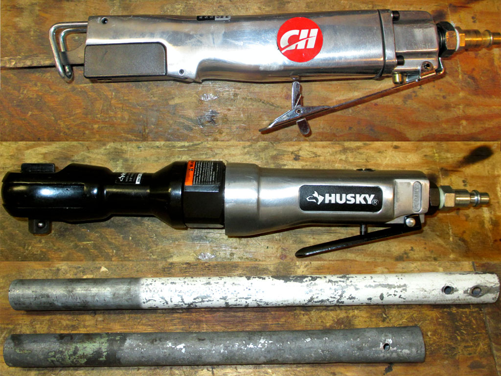
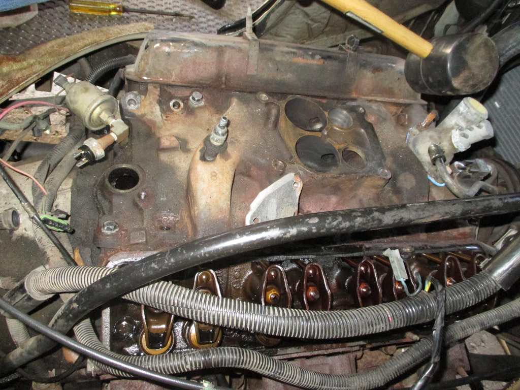
For a job of this size, I broke out the heavy artillery. Air saw for cutting, air ratchet (for those 6 inch long bolts that GM loves to use everywhere) and a breaker bar for leverage. In removing the exhaust manifold bolts, I only had enough room for the 3/8 ratchet, so extra leverage was needed to break 'em loose. I didn't have a 3/8 breaker bar, so I keep a couple lengths of steel pipe in my socket drawer. A little sloppy to use, but who wants to pile in their car, drive to the hardware store, then drive back? Sometimes you gotta use what you've got on hand.
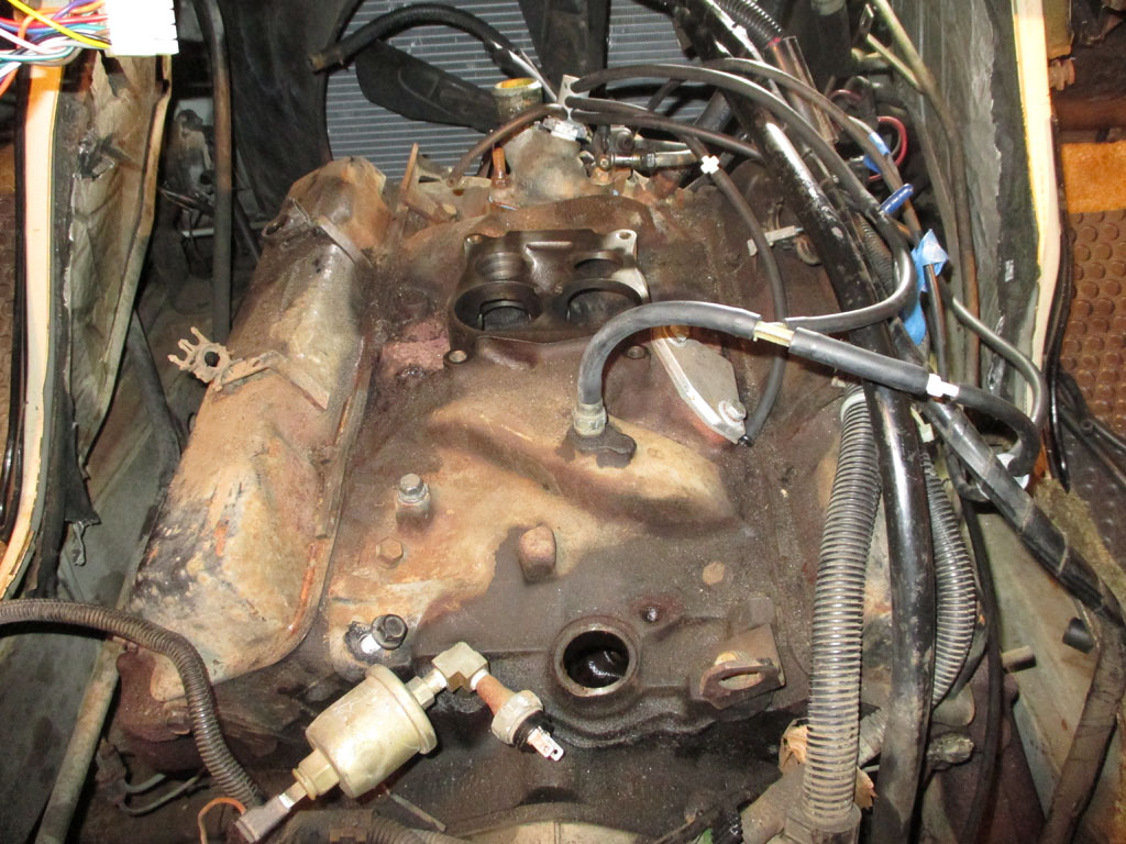
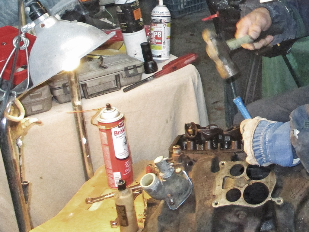
We started this around 10am in the morning. Hard to believe, but by 8:30 at night, we'd only gotten this far. The way Chevy made the intake, there's practically no room to get a socket or a wrench on some of the bolts, particularly those on either side of the carb mounting flange. Add in years of rust and a few of the 9/16 bolts weren't quite 9/16 any more. A standard extension hits the carb flange at such an angle that the socket cannot seat fully on the bolt head.
Reese's Law
"The last bolt in any given assembly will be the hardest to remove and have the worst accessibility imaginable."
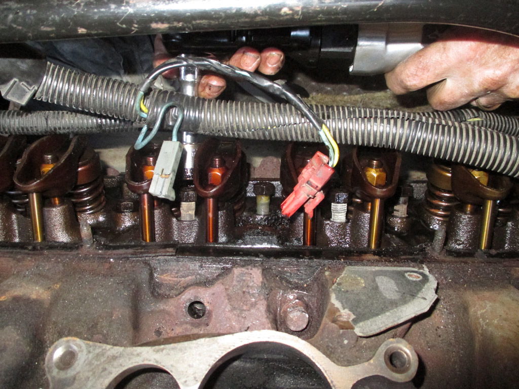
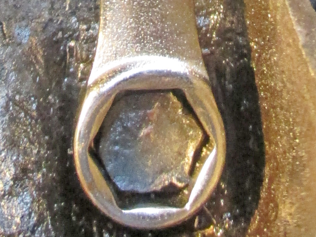
Every other intake manifold bolt came free except this one. It should be a 9/16 but is so corroded we could not get a socket on the head. Along about this time I also discovered that (other than an orphan wrench or two), all of my box wrenches are 12 point versions. Perfect.

REALITY
2017
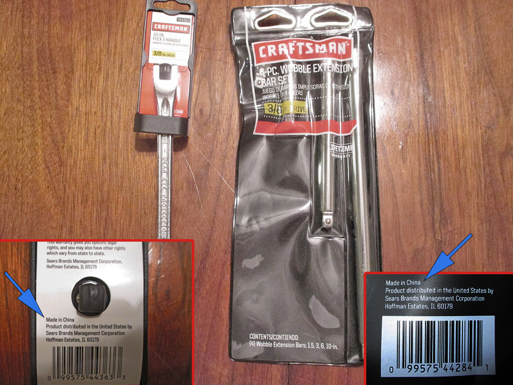
There was a time when faced with a tool need, my first reaction would've been to hop in my jalopy and head to the nearest Sears store. I use the past tense because this is no longer a viable option. 2017: Craftsman wrenches - made in China! Craftsman socket extensions... made in China. I bought the "Chinaman" wobble extensions only because they were on sale for $9.99 from $24.00.
A short time later, I bought a set of Craftsman 6 point wrenches (and an S-K 3/8 breaker bar)... all made in USA! How did I manage this after my in-store experience? Simple, I fired up my computer, surfed to the bay of E and found what I was looking for in American made tools. To me, the price I paid was worth the quality of the tools I've used my whole life. Done!
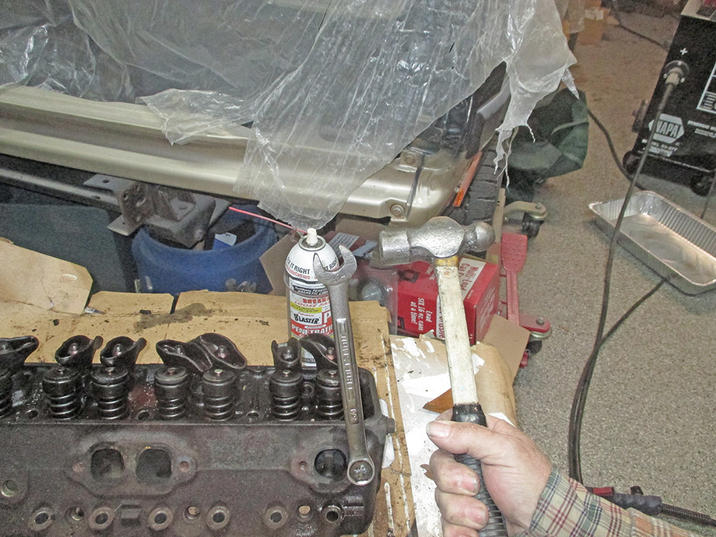
With my new Made In USA tools on the way (Booyah!) it was time to get back to work. Prying on the lip of the cover with a screwdriver simply bent the lip up. These babys were really on there. Time for a new approach.
Go big or go home. As long as you don't care too much about the factory valve covers (and I don't), this was a quick and easy way to loosen things up. In the end we didn't do too much damage, but I'm thinking some retro aluminum finned covers would be cool.
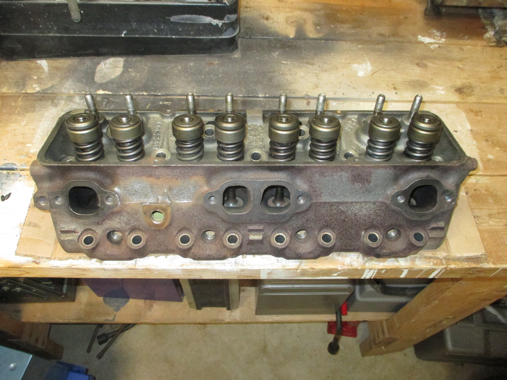
With no way to get the last bolt loose so we could pull the intake and then the head, we decided to pull the intake and the passenger side head at the same time! It was heavier to do it this way and a lot of work to get up and off the block, but we prevailed. With everything sitting in my basement where I have better access now I can devise a way to remove this accursed bolt.
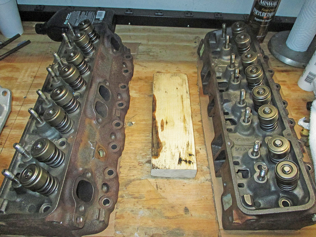
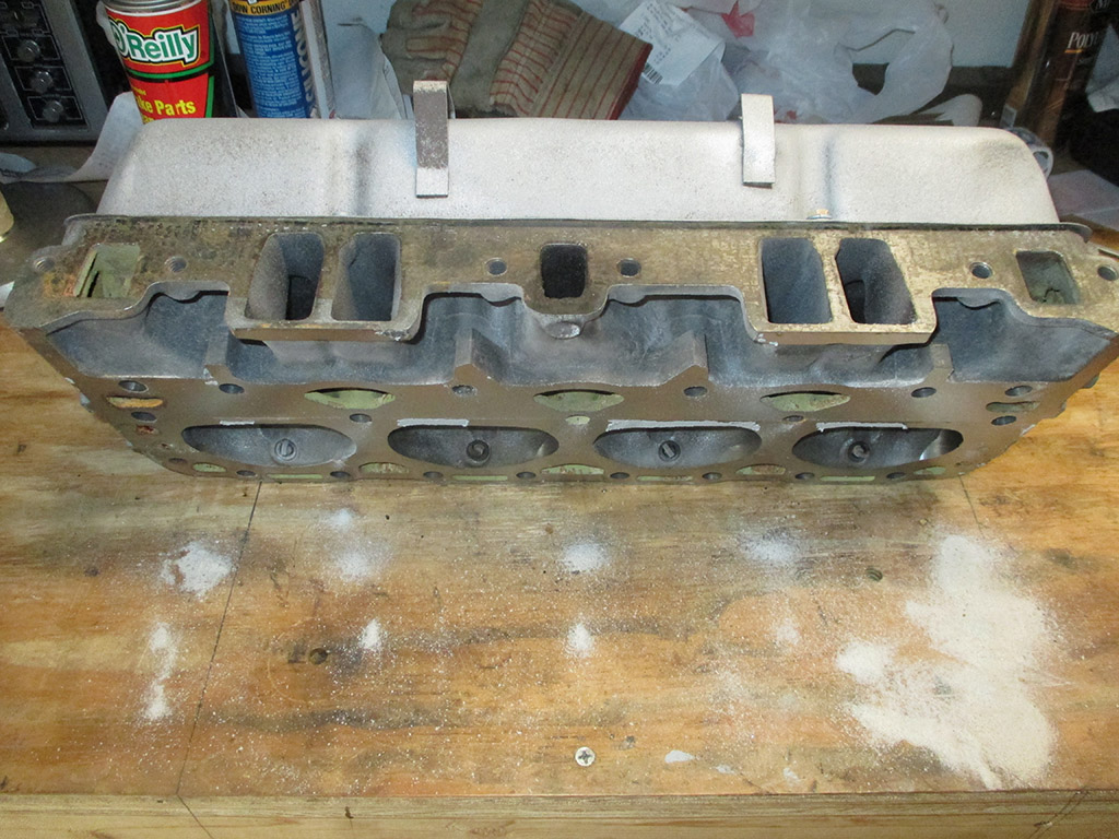
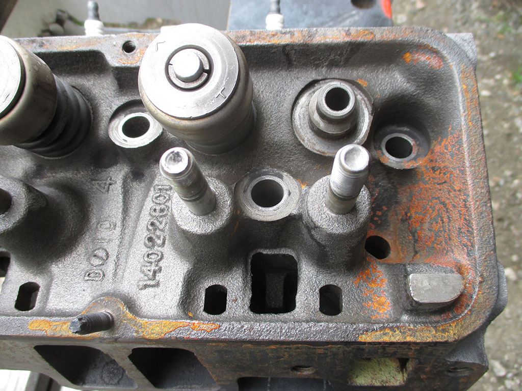
On the left we have your basic integral head/manifold combo. Once I solve this little issue, all I have to do is find a local machine shop (that should be fun), who can give me the low down on the condition of my heads. Hopefully I can get them reconditioned for a reasonable price.
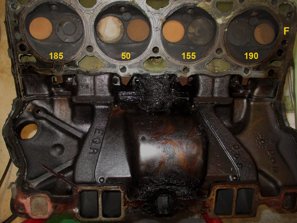
STUCK TOGETHER
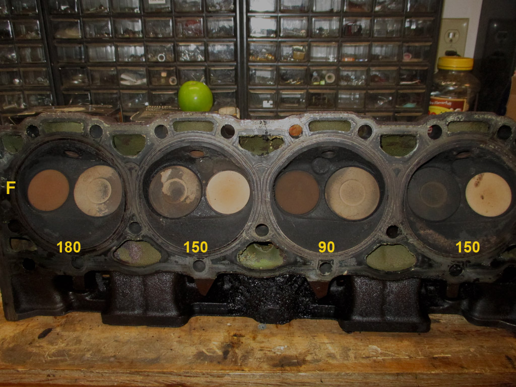
DRIVER'S SIDE
To the right, the driver's side head, along with the compression test numbers for this side. I really don't want to pour a ton of cash into a "boat anchor" 305 when a 350 can be built for more ponies and will fit in the same space. It's all going to boil down to cold hard cash.
Another day, another round of Car Guys vs. the bolt. We slowly soaked the area with heat (nothing red hot) so as not to crack the intake which is cast iron. The heat may have helped, but in the end brute force was called for. Two hours of soaking with PB Blaster then hammer and chisel work.
The trick you see, is to hit it at just the proper angle to cause the bolt to turn, not bend. Too steep an angle of attack and you'll simply bend the head of the bolt over instead of making it turn. Lots of finesse and patience required, and we still bent it a bit. Then again the occasional whack full on helps to shock the threads and help the penetrating oil seep into the deepest recesses.
At this point we've managed to unscrew the bolt enough to expose the threads, the remnants of a bracket that once held up the air pump valve and a washer. Not gonna kid you, the whole tap it left, tap it right, check progress took a long time to do.
Part of the problem with this approach is that you cannot simply build a rhythm of steady blows since you are tapping first one way then the other. With all the fooling around with cars I did in my youth (being a "damn grease monkey" according to my Mom) pulling an intake manifold and head was low on my list of automotive accomplishments.
I did it on my '76 Pontiac Grand Prix. The junkyard 455 replacement motor was burning oil so bad I had a better smoke-screen than 007. I ended up doing a "one-holer" (honing one cylinder and replacing the rings on a single piston), the best a broke college student could manage on fixed funds. Later I would repeat the exact same procedure my '76 Chevy pickup when the inline 6 decided to burn a hole in one piston due to detonation.
After all the pounding this baby took, I was still able to fit one of my new 6 point 13mm wrenches onto the head. All the other bolt heads were 9/16" but all the chiseling turned it into a metric bolt. I didn't really care as long as I was able to get something to fit on the head of the bolt. A little worrying back and forth and I had it out in a jiffy. Finally!
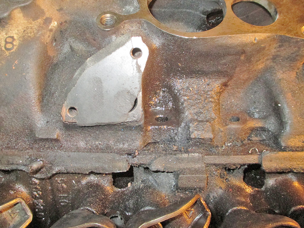
Due to the way the intake manifold runners flow with the EGR valve mounting pad right above this location, access couldn't have been worse. At least no expensive parts were harmed during this extraction. I had fabricated an aluminum block off plate for the EGR when the vacuum nipple rusted off the damper that controls it.
I wasn't quite prepared for how long it took to finagle this little so-in-so out of the deep hole it was lodged in. I knew it was going to come out one way or the other, but working it in and out bit by bit was what finally worked.
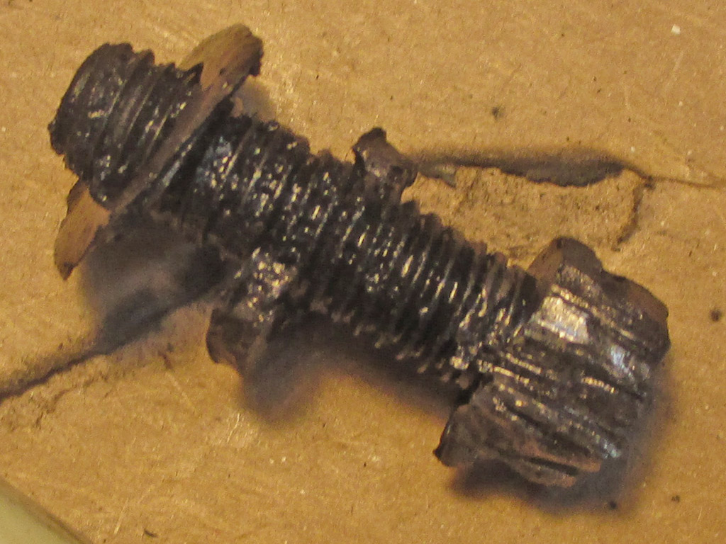
With the toughest nut finally cracked, it was time to fix the last little fastener issue. Despite our best efforts, we did manage to break off one exhaust manifold bolt off in the head. We found a nut that was large enough to just fit over the threads of what remained of the original exhaust bolt. Welding the nut to the broken off stud gave us a bolt again.
BUSTED
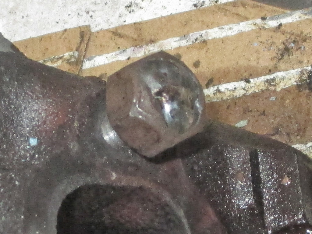
WELDED
HAMMERED
Welding the nut to the stud also applied a lot of heat to the threads. Next, it was time to grab a hammer and start working. A couple of taps one way, then another couple of taps the other way until the bolt could finally be moved back and forth with the wrench alone. Bolt removed!
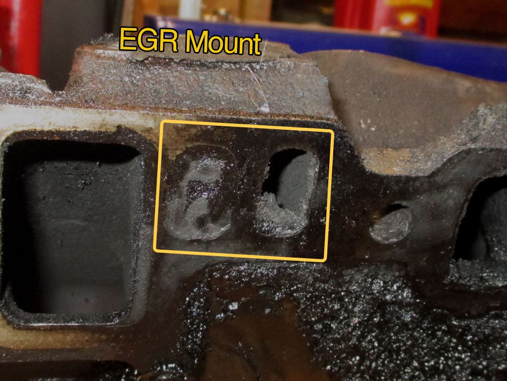
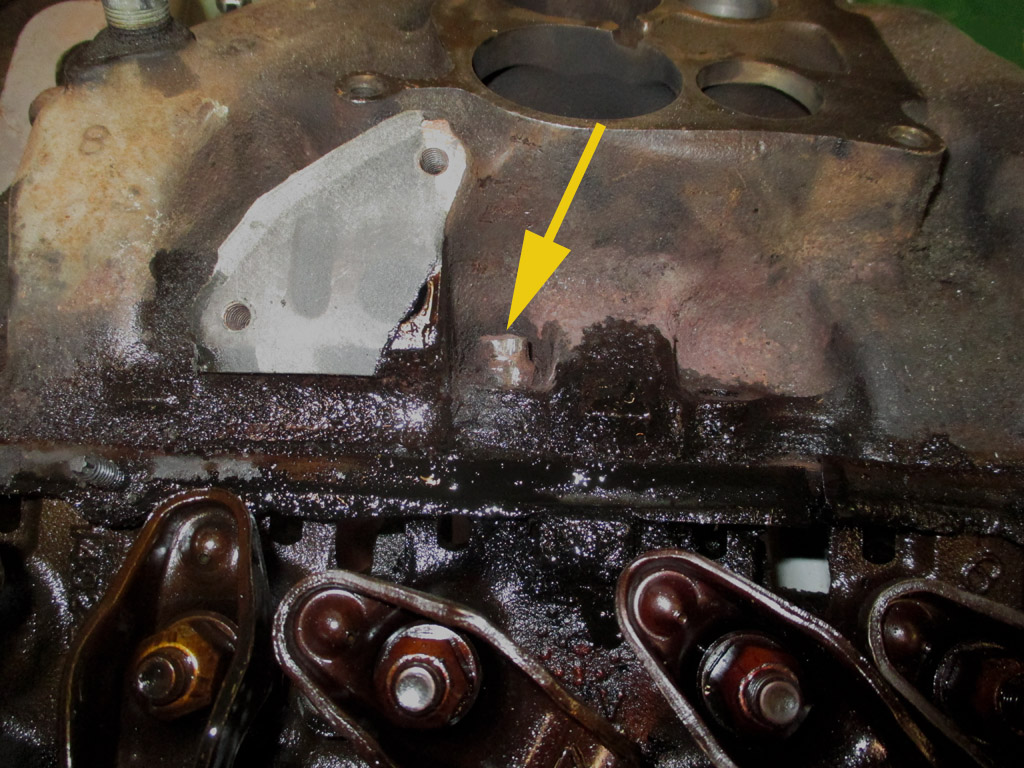
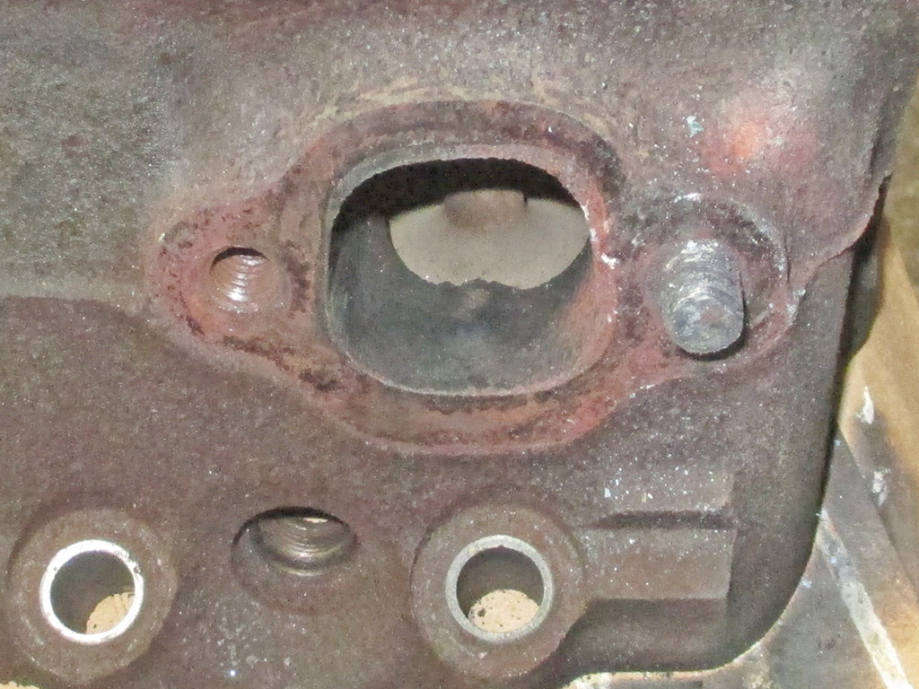
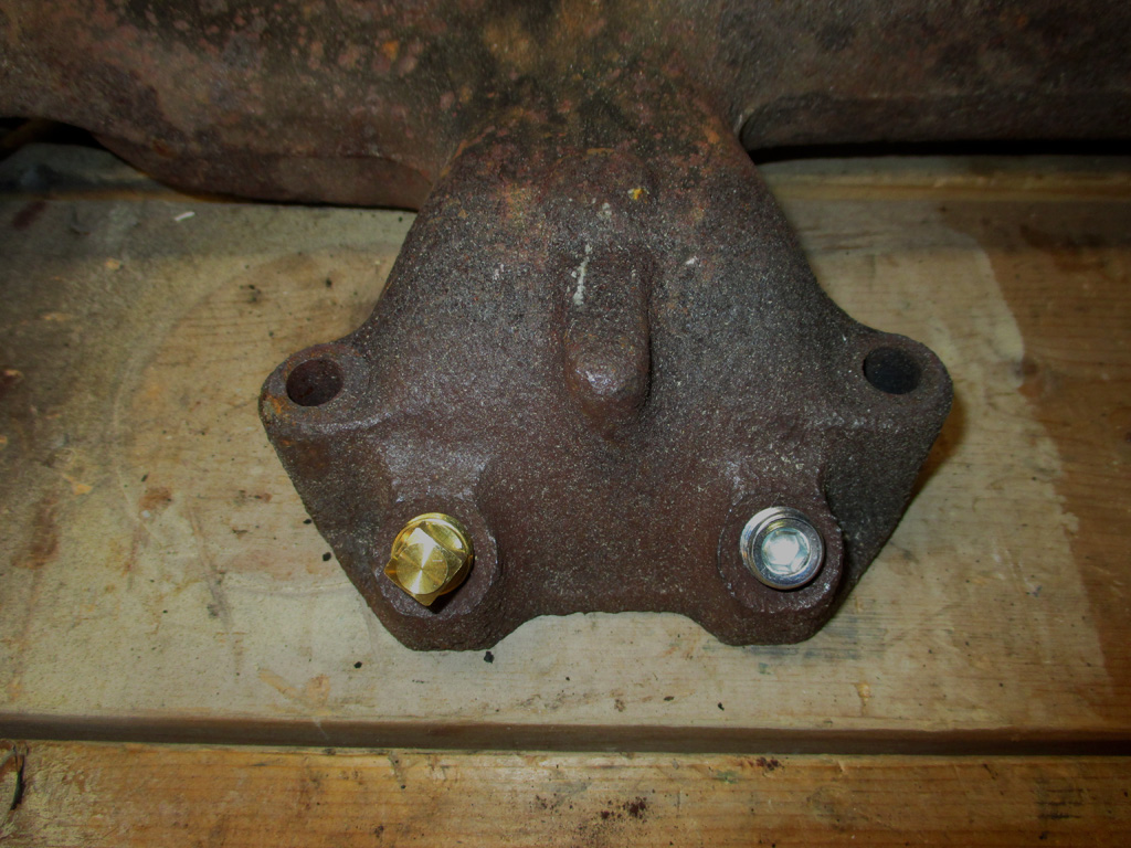
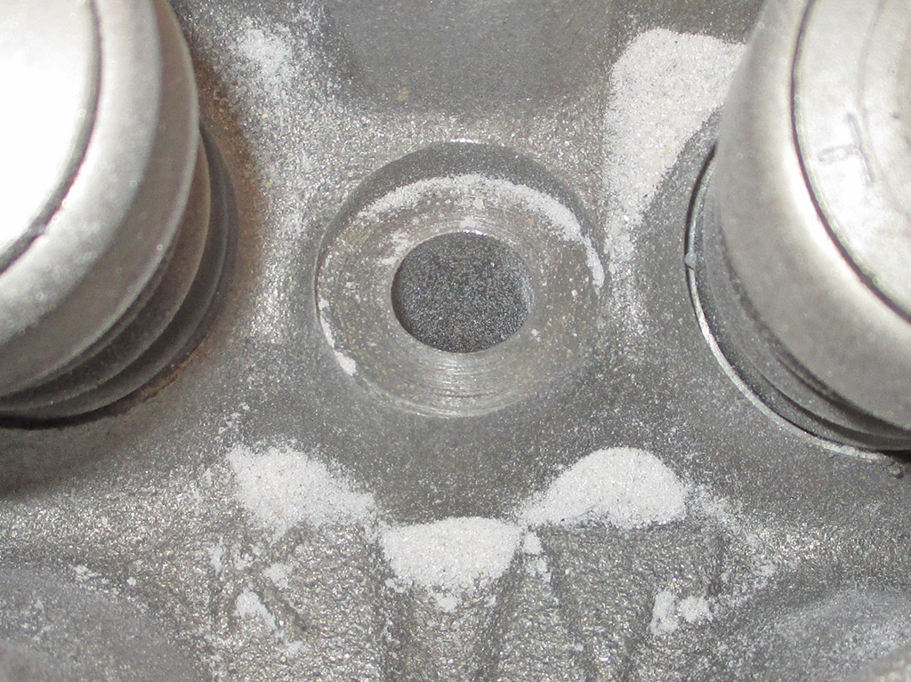
When the vacuum nipple rusted off the EGR valve, I removed the hose and plugged it with a screw and to prevent a vacuum leak. I've since been told that's not the best idea. With the manifold removed we can see one port fully plugged up the other partially obstructed.
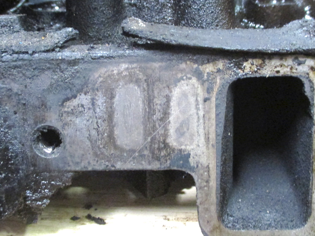
My initial theory was that the 305 had been fitted with earlier heads. I figured the two "ghost marks" seen here on the head were where the EGR ports on the intake manifold mated up, essentially rendering the EGR valve inert. That meant that the engine had been torn down previously. Could this be part of the reason the van seemed to pull pretty good for just having a 305 under the hood?
I have since learned that the answer is no. The two passages in the intake are part of the casting process and do not connect to the head. The EGR takes exhaust gasses from the crossover passage used to heat the intake manifold.
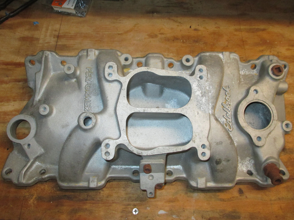
With the top end of the engine apart, I saw this as an opportunity for some upgrades. I consulted my extensive collection of Hot Rod, Car Craft etc., and decided an aluminum Edelbrock Performer intake manifold (SBC #2101) would be just the ticket. The Performer RPM is a high-rise clone of GM's original LT-1 350 intake manifold, which would've been my first choice. Taking into account the limited space of my van's engine compartment, I went with the low-rise Performer (non-EGR) instead.
I'd always wanted to put stuff like this on my car like the guys in the magazines did When I was younger, but I was broke at the time, so it never happened. Although I now have some money to put into my projects, I still like to look for a deal whenever possible. I spent 60 bucks for this one used, which seems to be in good condition as seen here. The nice thing about working with Chevy small blocks is that should I upgrade to a 350 at some point (provided it's a Gen 1 setup), I can swap this piece over to the new engine. Sweet.
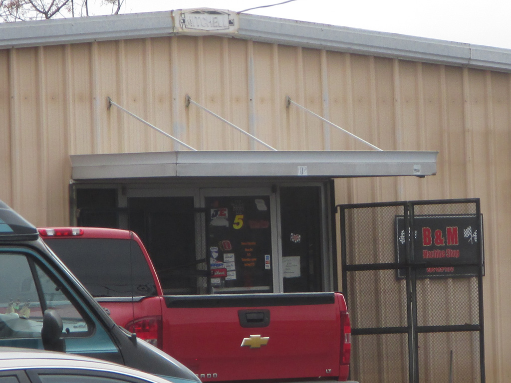
The week before Christmas and I finally located a machine shop local to where I work. They've been in business since the 80's and support local racers in the area. I was there on a Tuesday and the guy said they'd be ready by Friday.
The charge to Magnaflux and mill a fly cut (to eliminate any warpage) off the heads was $120 bucks including a Fel-Pro gasket set. The machine-shop guy said that the super-thin steel head gaskets are vulnerable to overheating warpage and the antifreeze in the combustion chamber had fouled the plugs giving me the rough running symptoms. We shall see.
When I went to pick them up I was told the valve guide seals were leaking (which I knew) so the total cost came to $170 instead. As long as this gets me back on the road, I can't get a 350 for that price. Not to mention all the futzing around with a valve spring compressor to replace the seals as well as the cost of the seals. As long as the mighty 305 lives... money well spent.
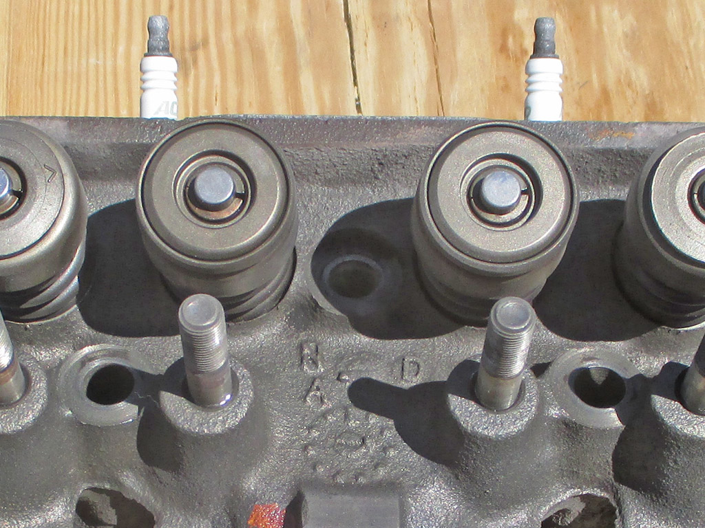
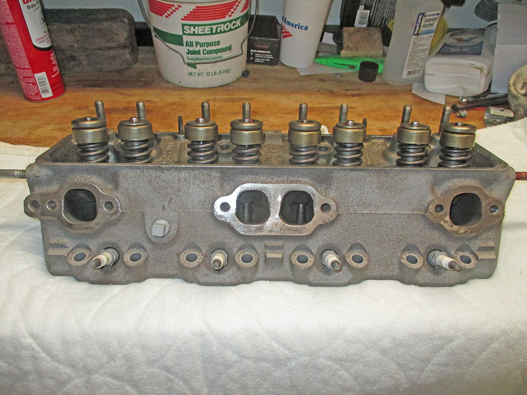
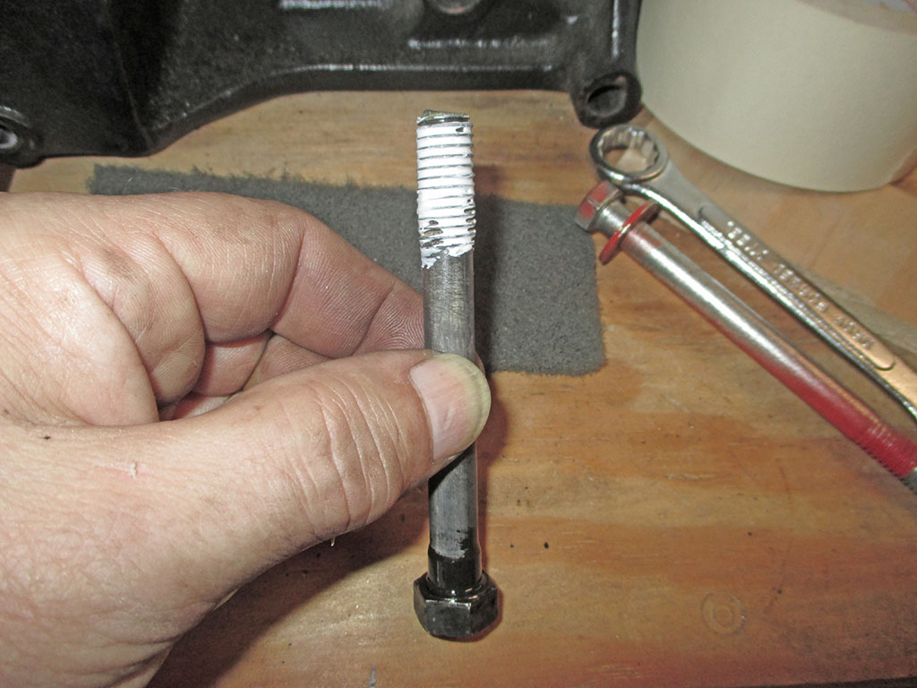
The heads have been returned looking remarkably clean. My plan at this point is to shoot some VHT semi-gloss black on them and then proceed with the installation process. The machine shop guy said I didn't really need new head bolts because the vintage engine I'm working on didn't use bolts that stretch like more modern engines. You know what this means...
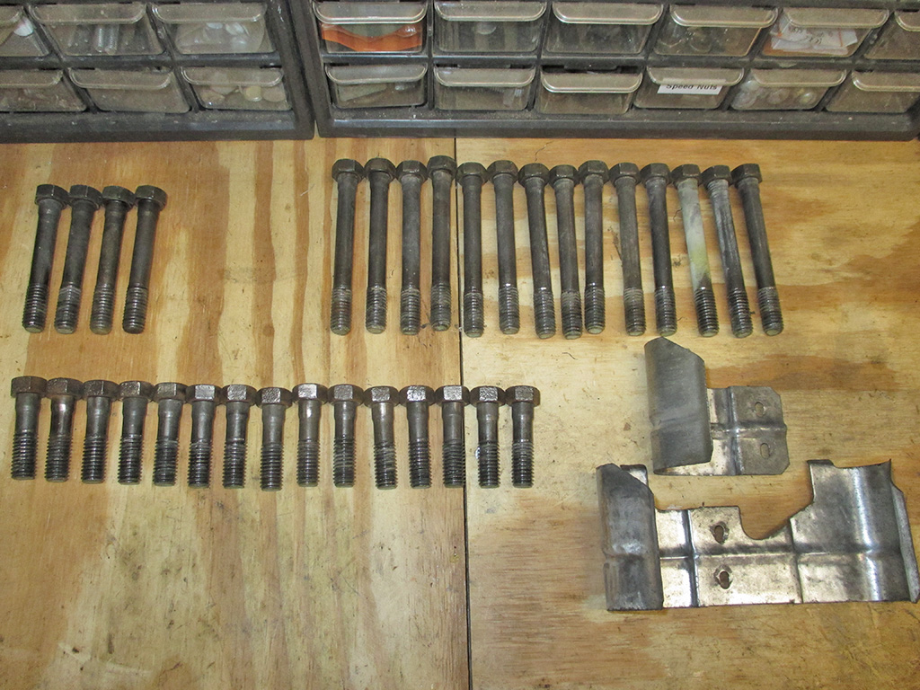
Take one rainy Saturday, add in a healthy dose of anal retentiveness, sprinkle with easy access to tools and this is what happens. Rather than spend cash where it's not needed, I decided to reuse what I have. This not only saves me money to use elsewhere on the project, but I know they're not made in China.
CHASING THREADS
FINAL PREP
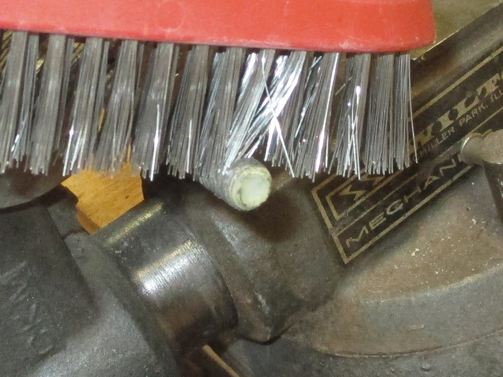
In for a penny, in for a pound. Next, I grabbed Mr. Dremel and went to work on the two spark plug shields I removed. I wore down two mini wire wheels on this job, but I can now hit them with some 220 grit and fog them VHT black.
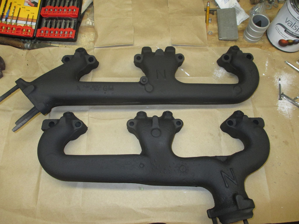
The end result. Not too shabby for the scope of my engine spruce-up project. Still left on the to-do list, pipe plugs for the A.I.R. fittings I removed from the exhaust manifolds and some new valve covers. I'll bet you didn't know that a Chevy Van uses specific valve covers now did you?
I have to admit, I wasn't prepared for the search for exhaust manifold plugs. The biggest hassle was figuring out the size I'd need. My thread checker said they were 14mmx1.50 but when I took a female fitting (that the original AIR fitting matched) to the autoparts store, they came up with 1/4 pipe plug.
They don't go in as far as the AIR fittings, but they do tighten up sufficiently to seal the manifolds. The square head plugs weren't doing it for me aesthetically so I'm going with the allen head style.
I looked at the freshly machined heads and thought they'd look good painted Chevy orange. That means removing the remnants of rust still clinging tenaciously to each head. A wire wheel would take care of the rust, but polish the surface. This is not good preparation for paint. My spot sandblaster would provide a good surface for paint, but will take me forever to accomplish. My air compressor cannot make enough air to supply the sandblasting cabinet I bought. Give yourself a little gold star if you can see where this is headed.
SORTA CLEAN
MASKED OFF
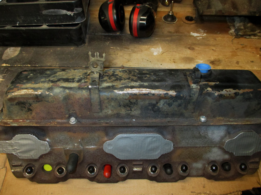
This means I have to farm the work out to a place that does media blasting. Of course before I can do that, I actually have to find such an outfit near to where I live (hopefully), that does good work. I've got to keep the blast media out of the heads. With that in mind, it became necessary to take the time and mask off EVERYTHING. I used Duct Tape and some Gorilla Tape for this. In hindsight, I should have used more.
PROJECT STATUS

So. Here's the passenger side head from my mighty small block Chevy, fresh from the media blaster. I'm pretty pissed off right about now. They sand blasted the valve covers (after telling them not to), and I can still see rust pits in certain areas, so I don't know if the paint is going to adhere well or not.
When you drop off your items to be blasted on Monday morning, are told they should be ready the following Friday, (the guy who helped me unload the parts wrote down what needed doing to each piece) would you think it was a professional operation? I did.
I wasn't expecting the owner to answer the phone Friday morning and say "oh we were wondering whose parts those were." He asked me when I had dropped them off and when I was told they'd be ready. I told him and he said they'd be ready that afternoon.
"What we're dealing with here... is failure to communicate."
Here's a shot of the driver's side head. Did they blast this from outer space or was the operator needing a cataract operation? Same blotchy, haphazard preparation of the surface. If this were the only issue, I might have discounted the results. Unfortunately, things are worse than they appear on the surface.
The place I took my parts to is (at least in theory), supposed to be open Mon-Fri 8:00am - 5:00pm, (coincidently the same hours I work), but this is the South and things tend to be... L a i i i i i d - B a a a a a a c k. They aren't open on Saturday either (perish the thought), so I had to go in late to work to pick up my parts. I probably should have looked them over better, but where I work is becoming rather strict about punctuality. I had places to be. Around 8:20 I finally managed to corral an employee and complete my transaction.
SAND HERE
AND IN HERE
I thought I'd masked everything off well, even wiping the surface with acetone to help the tape adhere better. In two places, the tape obviously didn't hold. Now I have sand in my valves. This was exactly what I was trying to prevent and why (if I'd had the proper equipment), I would have done the job myself. WTF am I supposed to do with this?

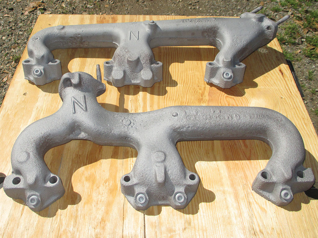
The exhaust manifolds (being what they are) fared much better than my heads. There are areas where the blasting was rather "light" by my standards, but the VHT paint I bought should stick. Mostly. I hope.
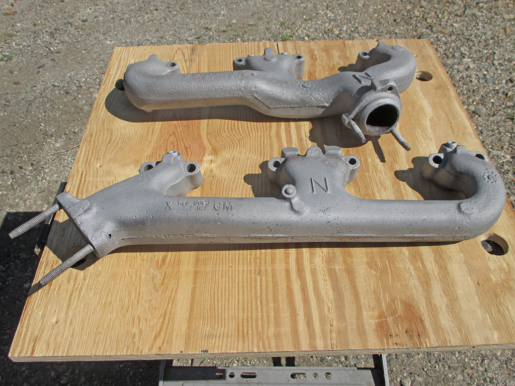
ANGLE 1
ANGLE 2
The VHT paint has some rather interesting instructions. It can be handled after three hours. Then it has to be cured. With heat. There are instructions to do this either on or off the engine. Hmmm.
In for a penny... I also disassembled the hot air stove tins and had them "blasted" as well. I think they were afraid to be too aggressive judging from the shot showing the rust left untouched. This is why (moving forward) I will do small jobs like this myself.
Outside
Inside
Rust Missed
Painted
When you give someone instructions (for a job you're paying for), you expect that they will listen to you and carry out your wishes accordingly. Evidently the place I chose does not subscribe to my philosophy. Needless to say I shall not darken the doorway of their establishment in the future.
I might've done better hiring a teenager who was just starting out with a home sandblasting kit. Or maybe a 5 year old with a pail of sand to throw at it. Jesus. I pulled the duct tape off the head and sand literally poured out onto my workbench. This does not bode well for what I have to do next. I don't have a choice. I'm going to have to tear each head down completely and clean everything. But first... I'm going to have to remove the valve covers and see how bad things are. I've been procrastinating, knowing what I'll find and not wanting to go there.
Expletives deleted. Use your imagination. I masked everything off to prevent just this kind of thing from happening. This is what it looks like when your carefully laid plan blows up in your face. With no real choice, I began the clean up process.
Not knowing how much sand was left in all the passages, I unfolded my Black & Decker Workmate, grabbed a scrap of plywood and set the head in place. I turned on the screamer-compressor, unfurled a hose that would rather have stayed coiled up and waited for the pressure to build. With my regulator set for 120 PSI I grabbed a blow gun and got to work. I got peppered pretty good with all the sand I blew out of the head. You would think that would be it and I could re-assemble the engine and be on about my other tasks. No. This was just the beginning.
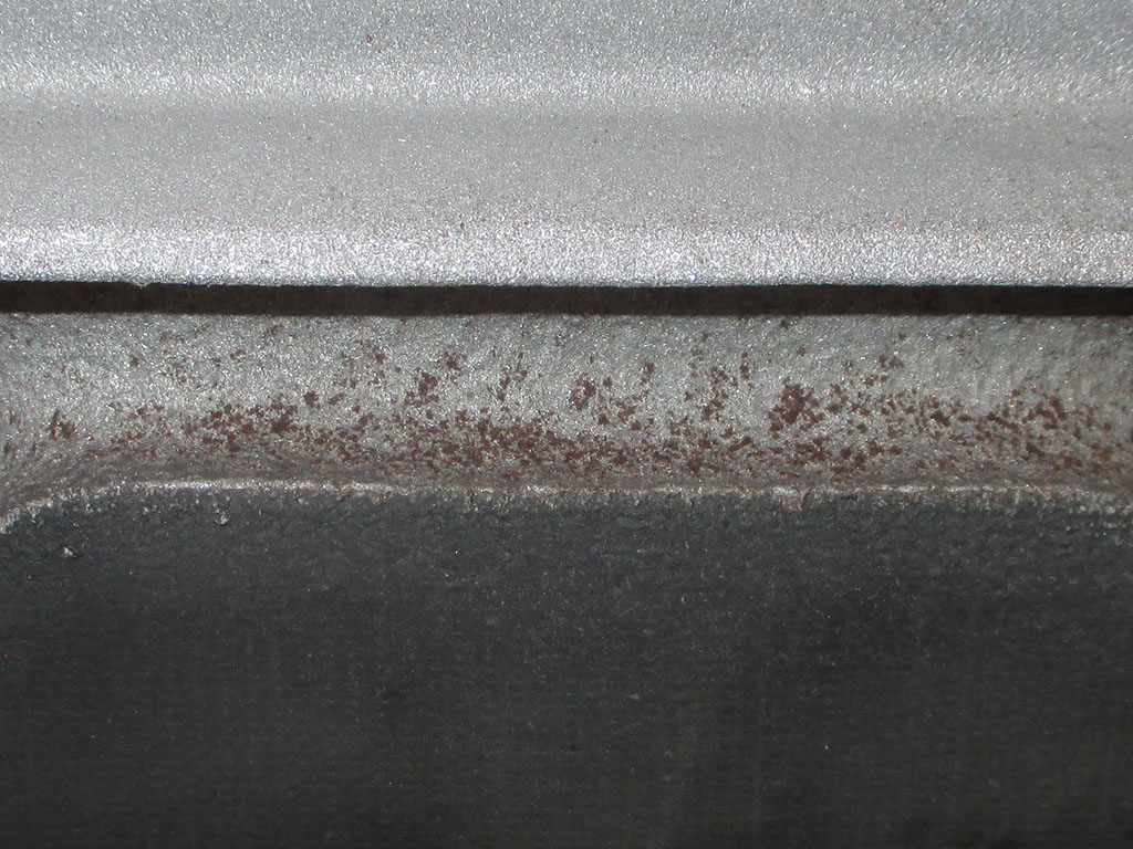
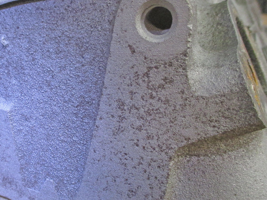
Once I blew as much grit as I could from the head with compressed air, I found another little surprise. Clearly they left these sitting outside where they were exposed to rain, hence the rust. After all, they didn't know who the parts belonged to so fuck 'em, leave 'em where you found 'em. Nice work philosophy in play here. How about this... how about asking your employees who dropped the parts off? Mr. Clipboard might be out for a day, but common people do any of you have a brain? That works?
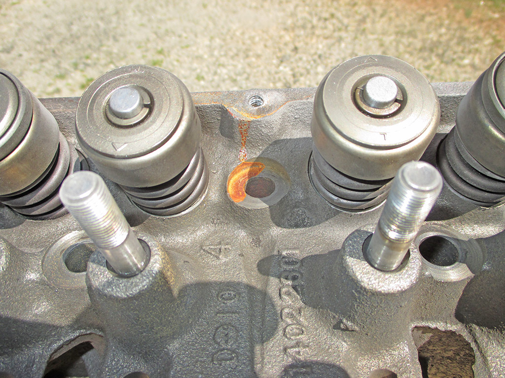
RUST HERE
HERE TOO
I know one thing. When I bolted the old valve covers in place to protect the head from the blasting sand funnel the sand inside where it could potentially do the most damage, there was not one speck of rust in the places where I now have rust. A-HOLES!!!
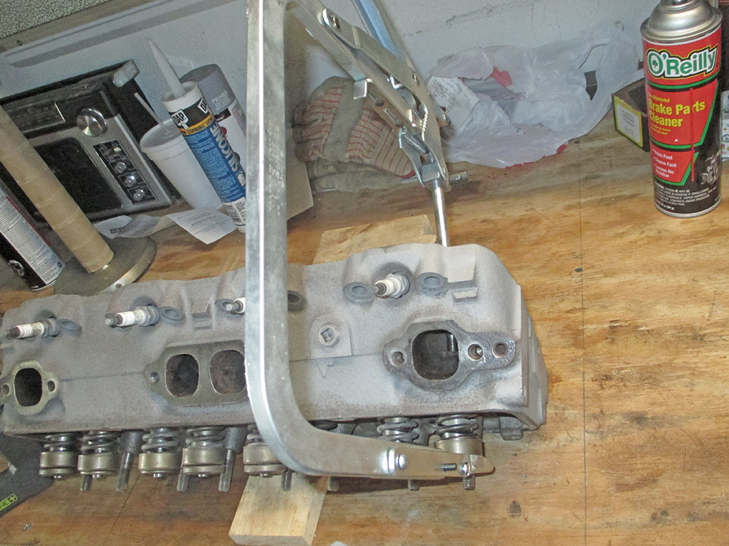
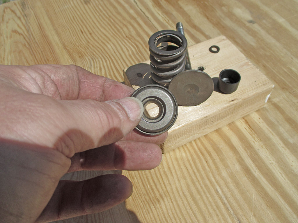
I purchased this valve compressor tool back when Sears still sold American made tools. Clearly it is designed to be used on a head that has been removed from the block. The procedure is completely different (requiring different tools), if everything is still assembled. I have used it successfully on my small engine collection too.
I really don't like playing with these. You've got the spring under pressure and then you've got to fish out the two split wedge shaped keepers, then carefully release the pressure on the spring, so you can remove everything and clean it. Then you get to repeat the process, releasing the pressure with the keepers re-installed, hoping they grip the end of the valve stem like they're supposed to do. At least once (so far) I was rewarded with an impressive SPROIIIINGGGG! as the parts went flying. I was able to retrieve all the pieces and got it all back together on the second try.
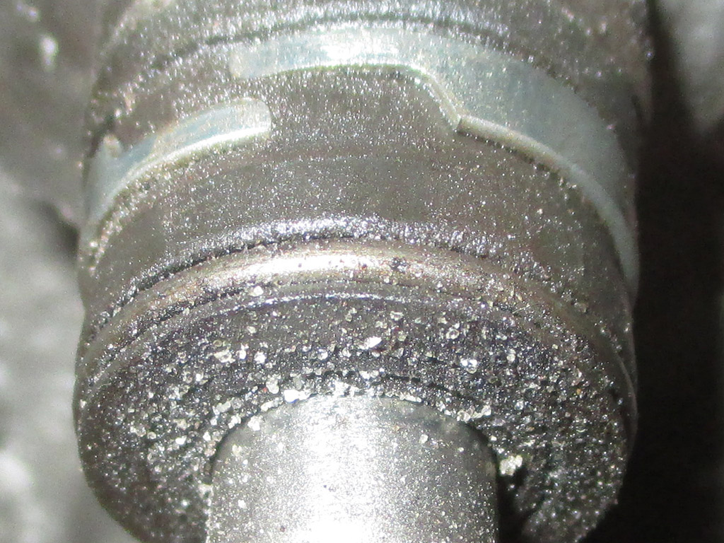
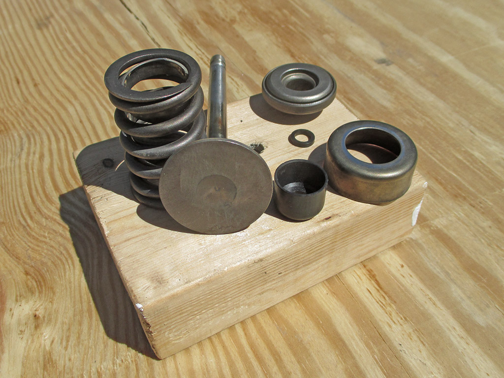
This is why I reluctantly made the decision to tear everything apart. The sand penetrated every square inch of the valve assemblies. If there was any residual oil left on any of these surfaces, it acted like glue, holding all the grit in place. With the spring removed we can see the valve stem and the stem seal both liberally covered with sand. There is absolutely no way of fixing this except to do what I'm doing. This sucks.
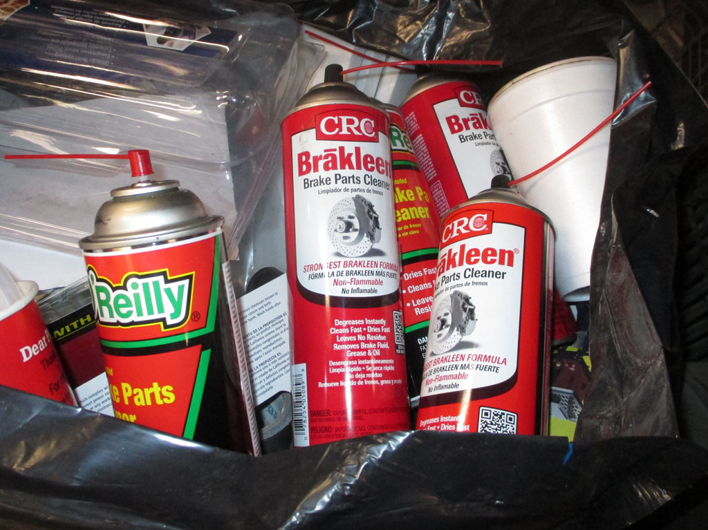
Before engaging in this war against the sand, it was necessary to gather the troops. I stopped by the local Advance store which was having a 2 for $6 sale on my chemical of choice. I'm not brand loyal as a cursory shot of my shop trash bag will attest to. I simply buy the cheapest stuff that will do the job. The day I was there, the store brand was $4.69 a can. I went home with 6 cans of the cheap stuff so I don't run out in the middle of the job.
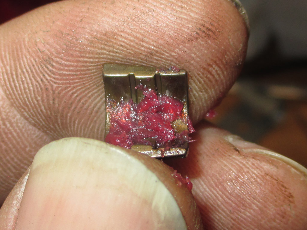
The spring had grit on it as did the valve. The little rotating device was really bad. You could hear and feel the grit inside. I blasted the cracks with brake cleaner and followed that up with compressed air. I repeated this process two or three times until I could feel it working smoothly. I didn't want to expose the rubber parts to the brake cleaner, so I used water instead, blasting the valve stem seal with the garden hose followed by compressed air to dry it off immediately. Before reassembling the valve-spring assembly I used brake cleaner on each valve stem bore and passage to be sure no grit remained.
Valve Rotator
1 Down, 15 To Go
Dab O Grease
First Half In
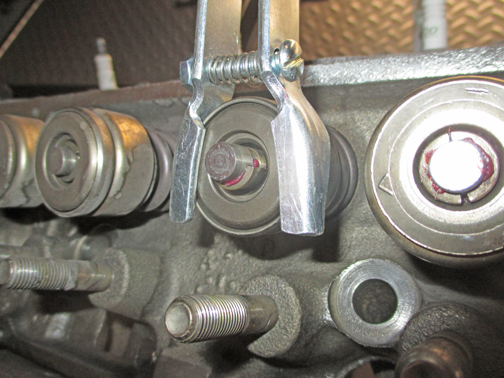
Once each assembly is clean, re-assembly follows. Valve back in, valve stem seal back in, O-Ring back on, then the difficult part. I'm not sure where I learned this little trick to keep the dastardly keepers in place, but it works. A little dab of grease on the keeper, press it into place, repeat with other half. They'll stay in place until you release the valve spring tool. The trick that worked for me was to release the tool quickly and smoothly. Too slow and something can catch one of the keepers and lift it out of place. At this point in the festivities I only have two assemblies left to pull, clean and reinstall. If all goes well I'll have everything back together in short order.
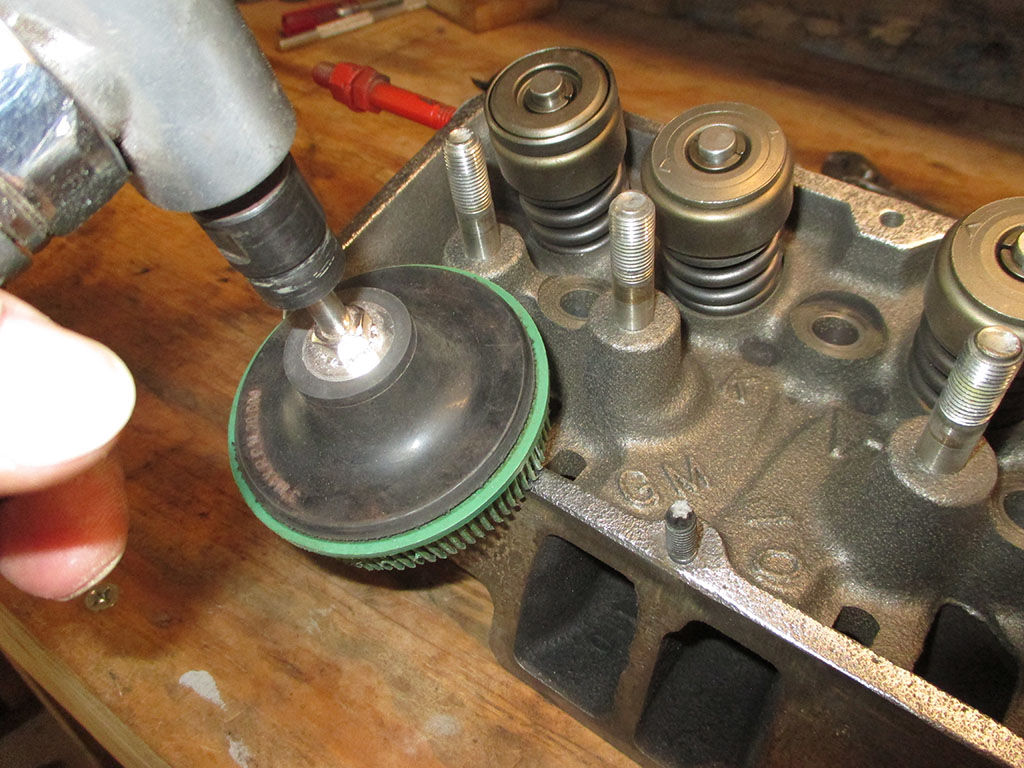
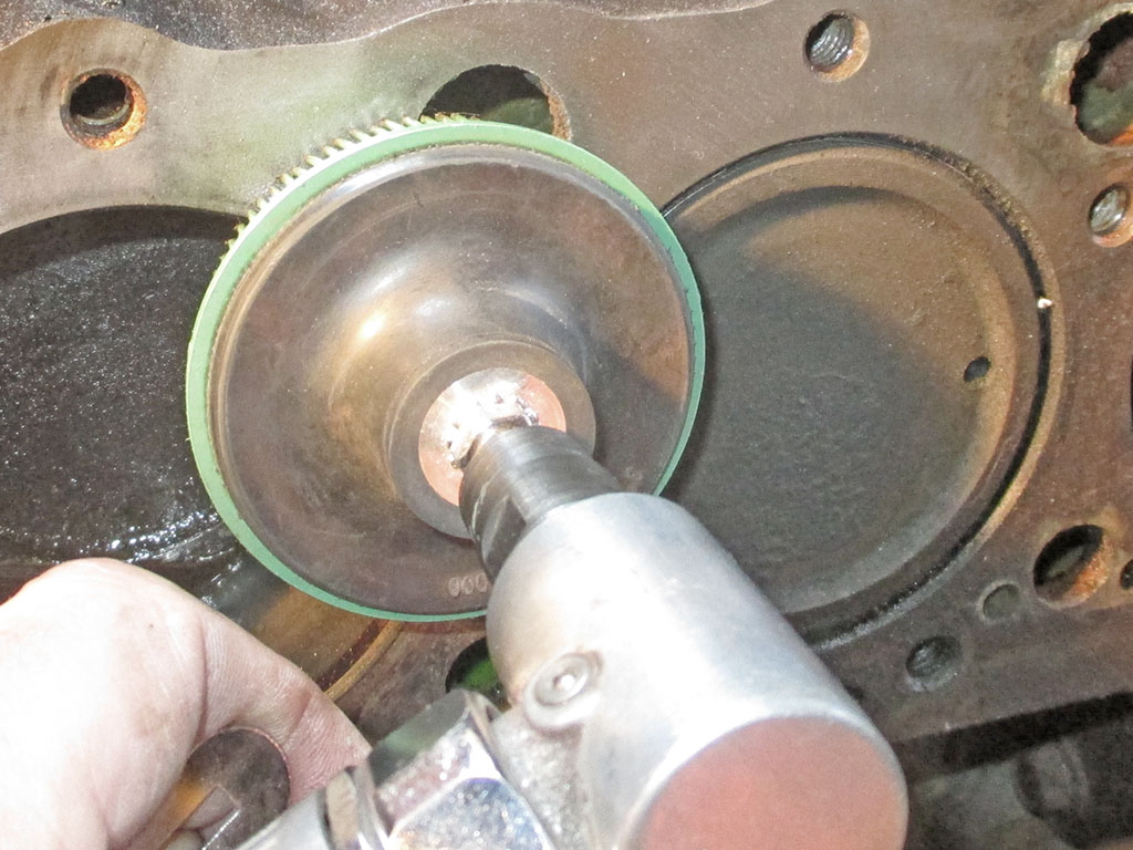
With all the valves, springs, seals etc. thoroughly clean, it was time to clean up the rest of the head. This is a 3M Roloc Bristle Disc which is embedded with a choice of abrasive grades, as the bristles wear down, more abrasive is exposed so you can work continuously. It was the perfect choice here, removing rust, bits of old gasket and gasket glue all in one fell swoop.
They make these in various grits and sizes, but I only have the 3" fine grit. Like most stuff put out by 3M, they're real proud of their products and charge accordingly.
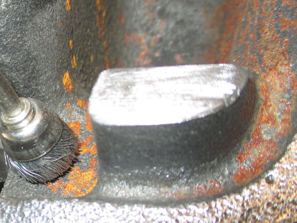
With the heavy lifting done, I turned my attention to the more intricate areas of surface rust. My go-to for jobs like this is my trusty Dremel tool. The secret to using this tool successfully is to NOT bear down on it. It's very tempting to do so and I tend to give in to temptation as the day wears on. Here though, I'm just starting out and the wire cup wheel came in real handy.
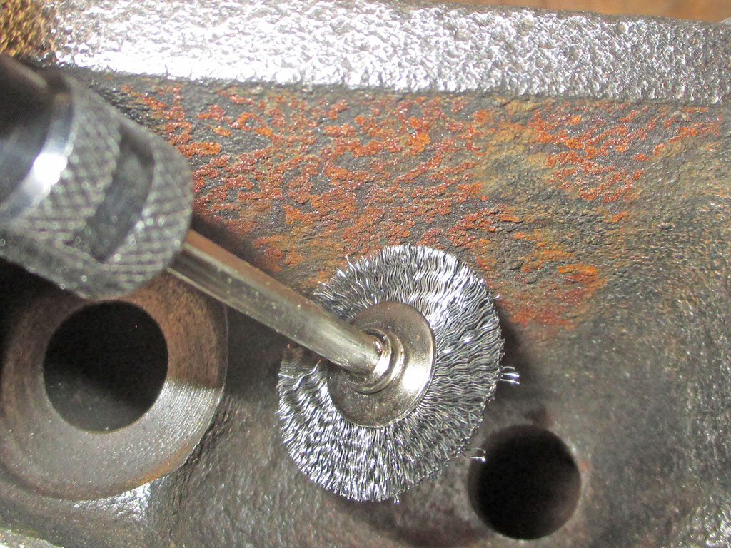
Just like the "full size" wire wheel I use in my drill or angle grinder, I also use 1" wire wheels with my Dremel. I buy 'em in bulk off Flea-Bay for cheaper than they're priced in the big box stores. I've found these work best if you keep the speed down and use a light pressure on the tool.
Once again, in some circumstances I'll bear down on it a little more in short bursts. Gotta be careful doing that though, because the tool tends to heat up real fast. Do too much of that and you'll find yourself buying a new high speed rotary tool. This one's relatively new, so I'm trying not to abuse it... too much anyway.
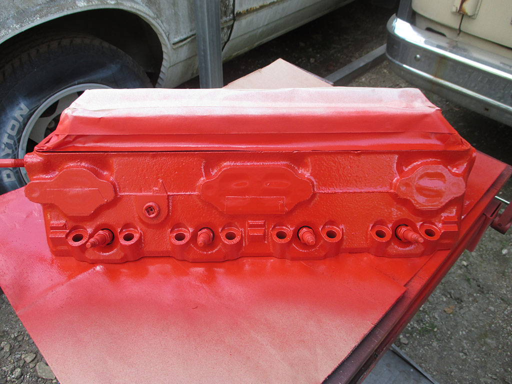
With everything cleaned and masked off, I painted the head with Duplicolor engine paint. All I had to do was bring the heads home from the machine shop and bolt them back in place and I'd have had a running van again. But NOOOOOOOOOO, that wasn't good enough. I had to get fancy. I had to try and make a show van out of my van. I didn't keep track of how many hours it took me to get to this point. Now I can repeat the whole process again on the other head. Wonderful.
I used VHT flat black paint (good to 1200 degrees?) on the freshly blasted exhaust manifolds. According to the instructions on the can you have to cure the objects painted with heat. You're supposed to bring them to a given temperature, then cool them off. You have to repeat the process a couple of times, each time taking the object to a higher temperature. You can do this on the engine or off. Either way you need the instructions on the can and I lost the flipping can! Par for the course in my world.
Once I get the second head painted it's re-assembly time!
Reassembly Begins
April/May 2017
Aaaaaaannnd we're back. After my head gasket project got spun off into the weeds by the idiots I mistakenly selected to media blast my heads, I am finally back on the tracks again. This is where I would be if I had "chosen wisely" in selecting a facility to blast my engine parts. Now... I can actually begin assembly.
EXHAUST PREPPED
HEAD PREPPED
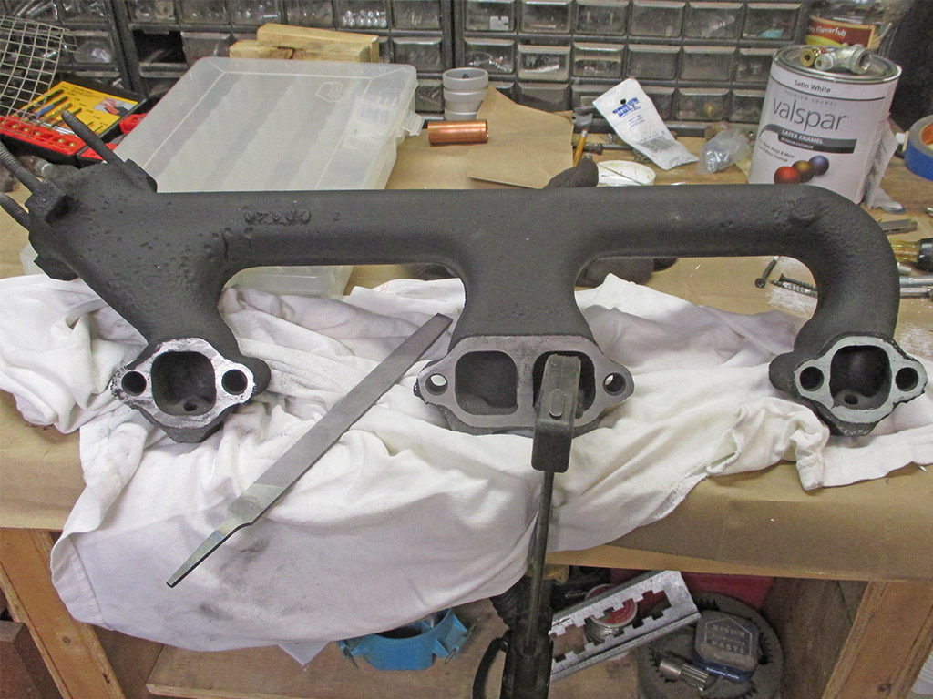
As a final preparation before assembly I took a file and carefully leveled the mating surfaces of both the head and the exhaust manifolds, so they will have the best chance to seal against my new exhaust manifold gaskets. The factory, having freshly machined parts assembled them with no gaskets. Time and corrosion have taken their toll and left me with mating surfaces that were pitted and would not have sealed well at all.
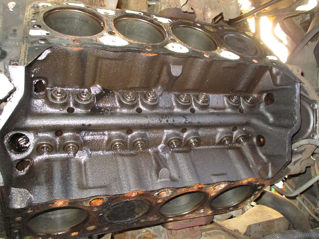
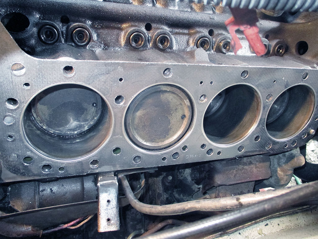
At the onset, I never thought that it would take 5 months to reassemble my engine. But there it is. I'm thankful that I prepared the block well for storage by wiping the cylinders with motor oil and covering the block with plastic weighted down with blocks of wood. I knew I'd have to clean the block before putting on new head gaskets and the heads, so I postponed that little task. Until now.
I was low on conditioning disks (got some later when I broke for lunch) so the Roloc Bristle Disc came to the rescue. Evidently moving the spinning disk over the water passages created enough of a vacuum to suck some old antifreeze out of the head and make a mess of things. I grabbed my antifreeze checker and sucked the remaining green goo out of the block to stop the splash back. Other than that unexpected bit of fun, this cleaned up the block effectively, albeit slowly.
According to the guy at the machine shop who did the fly cut on the head, the thin steel head gaskets were notorious for failing. This time I upgraded to Fel-Pro gaskets for the whole project. I only plan on doing this job once. You know, so I can go back to all the other stuff I was working on when this happened.
With the mounting surfaces cleaned, and the gasket installed the next task was to install the head. We used a rocker arm at each end of the head as convenient handles. I carefully laid it on the floor of the van, climbed in after it and set it on the old blanket we laid in the lifter valley to provide protection, one of us lifted from inside the van the other lifted from the mail slot sized hood opening.
The gasket moved on us once, mandating a second attempt. We had to lift the head into place while maneuvering it underneath two wire looms and the transmission filler tube. Just to keep things interesting.
With the head in place I started all the bolts finger tight. I had my air ratchet handy, so I ran all the bolts in snug, knowing the torque of the tool isn't very much at all. Per my shop manual, we used thread sealant on all of the threads and a dab of oil under each bolt head. Then it was time to grab my torque wrench and begin the tightening sequence. You basically start in the center of the head and work outwards.
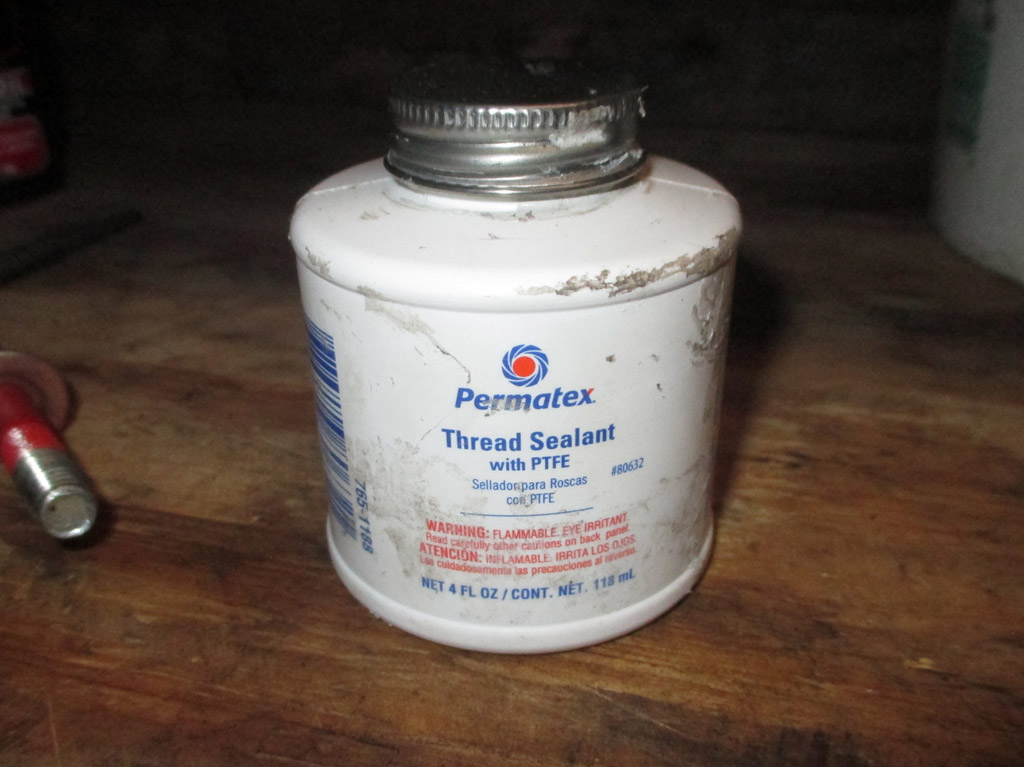
THE STUFF
READY!
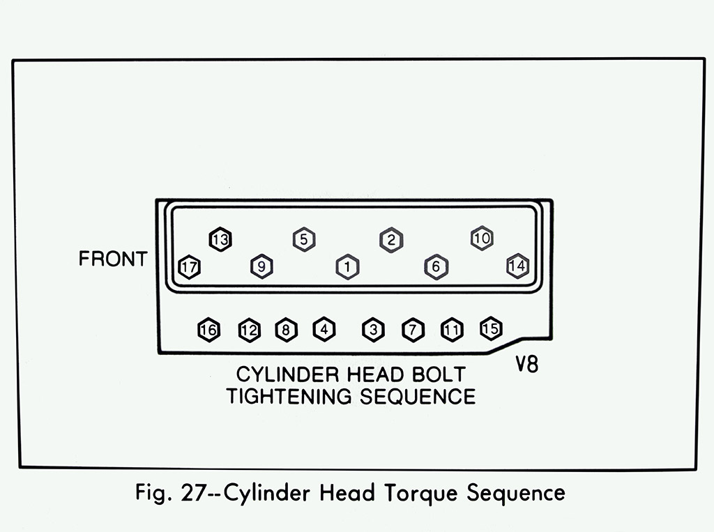
SEQUENCE
I made three rounds with the torque wrench. I tightened all of them to 20' pounds, then 35' pounds then the final 65 foot pounds. Needless to say I spent quite a bit of time bent over the hood and crouched in the footwell to bring the torque up to spec. I hope there's some Advil left in the medicine cabinet for later on.
With the passenger side install wrapped up, I turned my attentions to the oposite side of the block. Not seen is the medium grit conditioning disc I used in place of the bristle disc. At 2" in diameter I was able to get into tight spaces much easier. I wasn't using 3M products at this point, so it took some time to prepare this side of the engine.
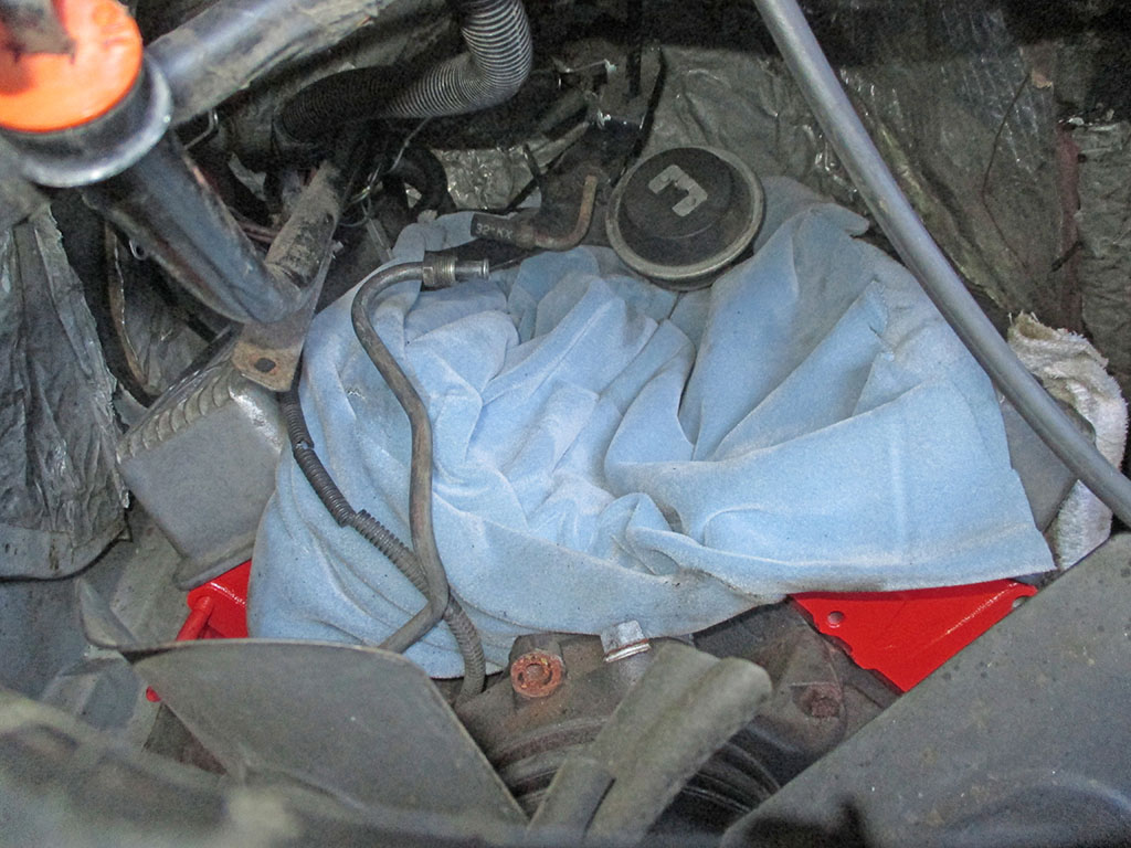
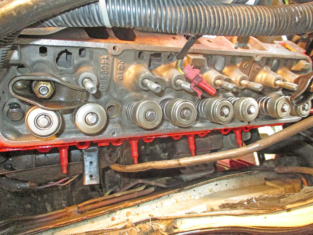
We wrapped up for the day around 8:30 at night. I set the new aluminum rocker arm covers in place, stuffing rags into the holes to keep moisture out. I used the old blanket we laid in the lifter valley to keep moisture out of the valley.
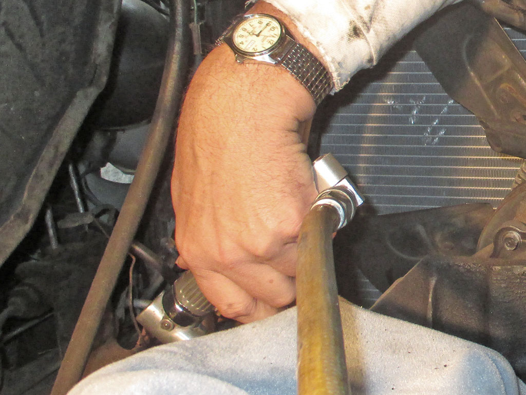
The next day I was back at it again. In order to set the valve lash, I need to rotate the crankshaft to a given position spelled out in my manual. That means getting a breaker bar on the crankshaft bolt. That means I need to remove the radiator (and shroud), to make room for manipulating the breaker bar. Yeah, that's about the size of things.
With room to work, the task at hand became rotating the engine to where cylinder number 1 is at top dead center. This really works best as a two-man job. One person rotates the crankshaft (keeping a sharp eye out for the timing mark on the harmonic balancer), while the other watches when the valves open and close. With the timing mark at TDC and both lifters all the way down, you can adjust the rockers. A deep socket, extension and ratchet were needed to turn the center bolt of the balancer.
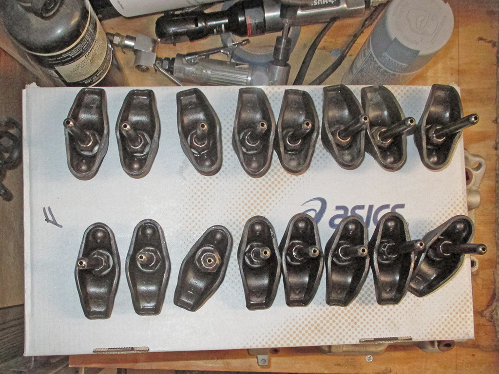
Every resource I consulted stressed the need to keep everything in order so it can be put back in the exact same place it came from. I found an old shoe box that wasn't busy, punched some holes in the top of the box, marked the "front" relative to the front of the engine and removed one rocker/pushrod/nut/pivot at a time and placed it in the appropriate hole in the box.
One by one, each assembly was re-installed in the exact position it was removed from. This will prevent premature wear, catastrophic engine failure and early onset baldness. Then the air ratchet was used to snug up each adjustment nut. That was the easy part.
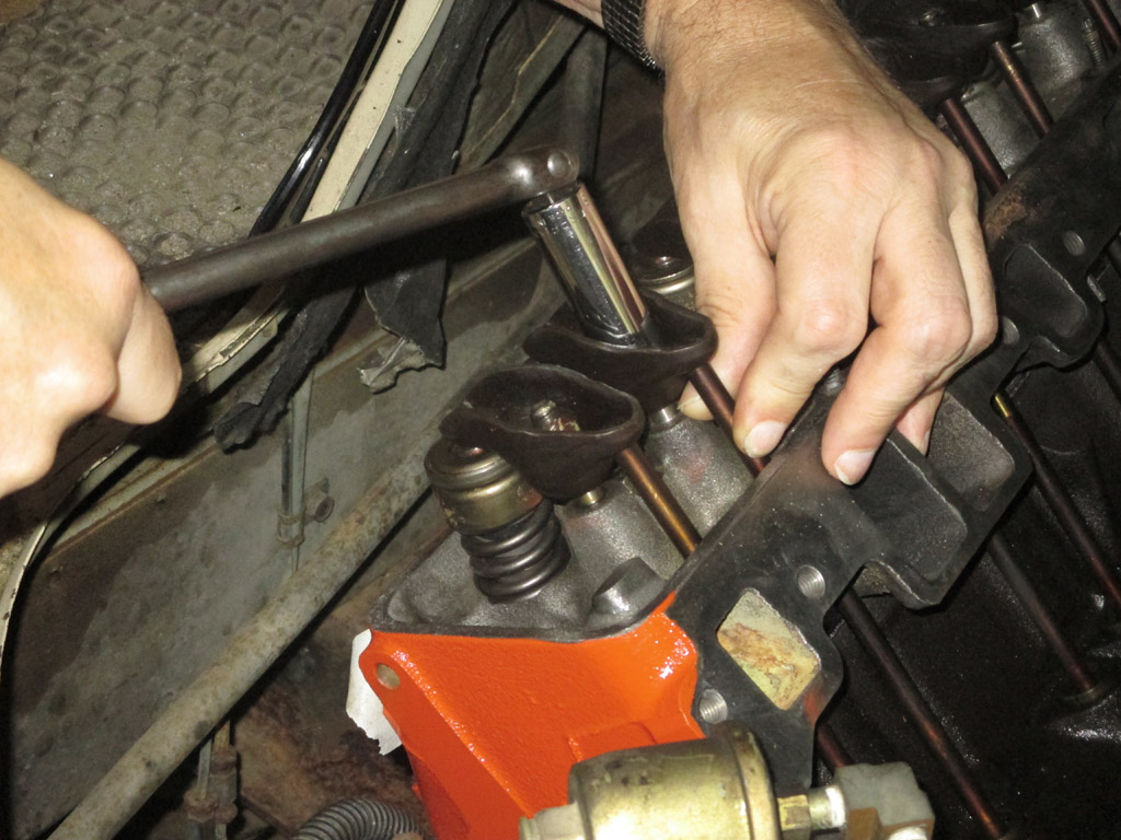
Once you get close, you have to take the slop out of the pushrod/rocker arm. I used a 3/8 breaker bar with a 5/8 socket. You rotate the pushrod back and forth between your thumb and forefinger while tightening the rocker arm nut very slowly so you can feel for additional drag. Once you feel the drag, stop. You are now at zero lash. It also helps to keep the socket a little high on the nut so you don't give yourself a false reading by exerting pressure on the socket.
The factory shop manual I got for my van specifies one full turn past zero lash. My Chilton manual says 3/4 turn, some Youtube videos say 1/2 turn, so pretty much anywhere between 1/2 and one full turn will put me in the ballpark. I guess. Nothing like a bit of ambiguity to remove any sense of doubt the process is being completed correctly, now is there?
Hardware
May-June 2017
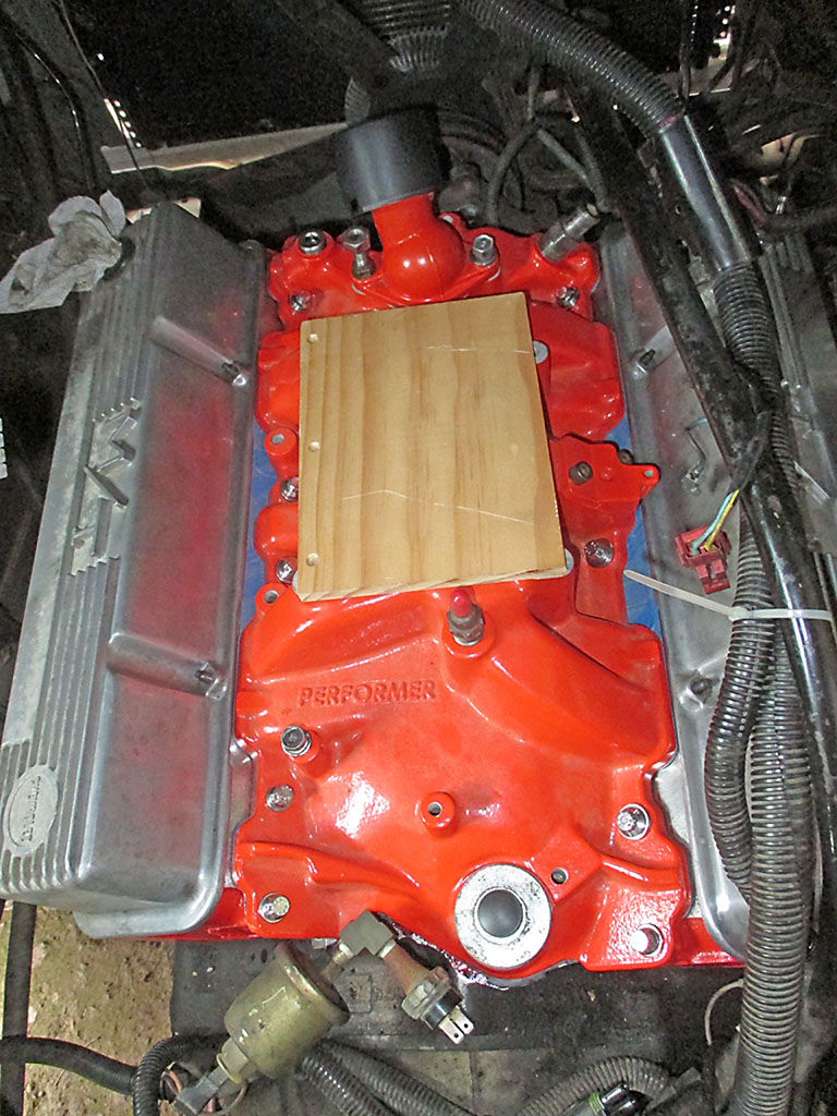
I purchased an Edelbrock Performer intake manifold at a swap meet for $60 bucks. Powder coated in Chevy orange no less! The grungy old OEM bolts weren't going to cut the mustard anymore, so I decided that while I was at it (oh no), I would upgrade to stainless steel hardware (DON'T DO IT!) to reassemble everything. And awaaaaaaaaaaaayyyyyyy we go!
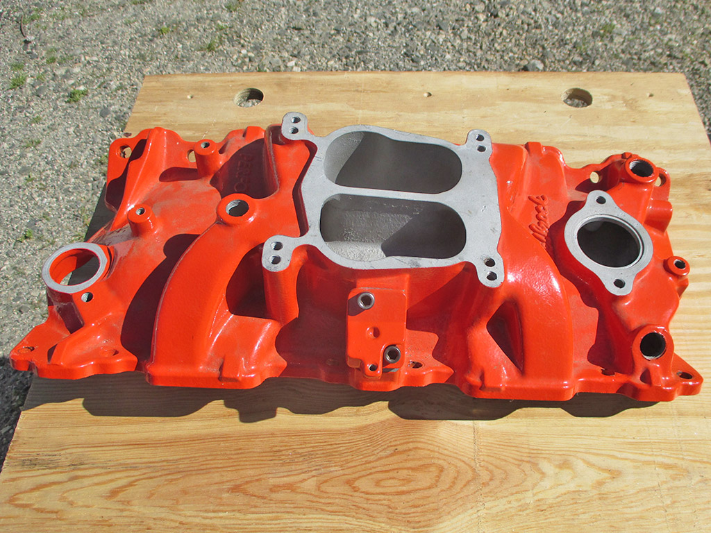
EDELBROCK 2101
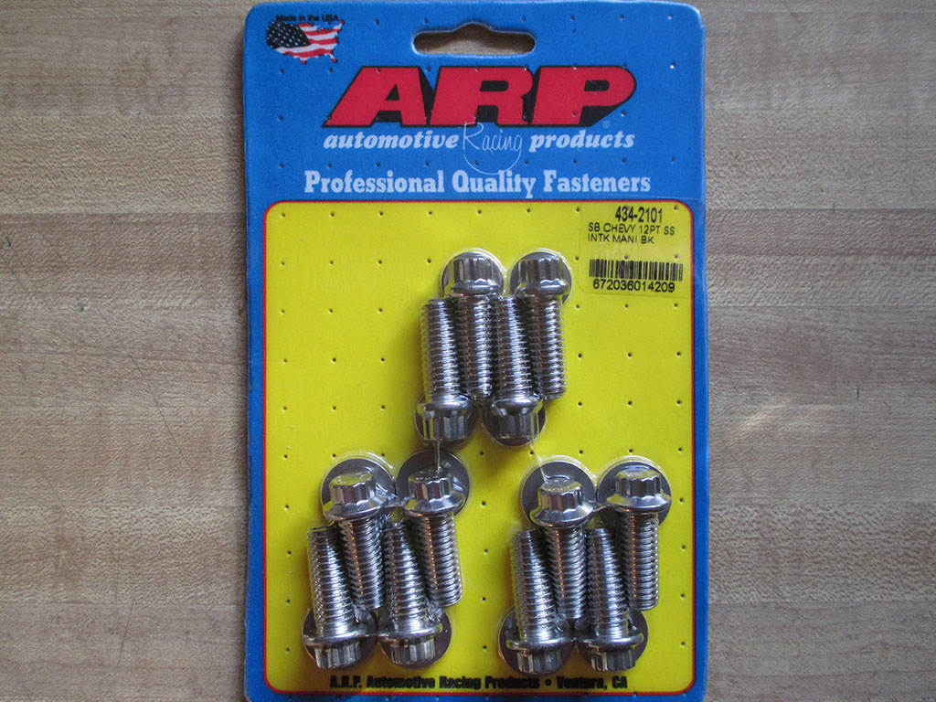
ARP BOLT KIT
ARP makes specialty bolts (in the good old USA no less), and finding a kit to install the intake was not problem at all... at first. The guys at Summit Racing steered me to the ARP intake manifold bolt kit for small block Chevy engines 434-2101. The Edelbrock intake manifold number is also 2101, so this should be the kit I need. Uh... not quite.
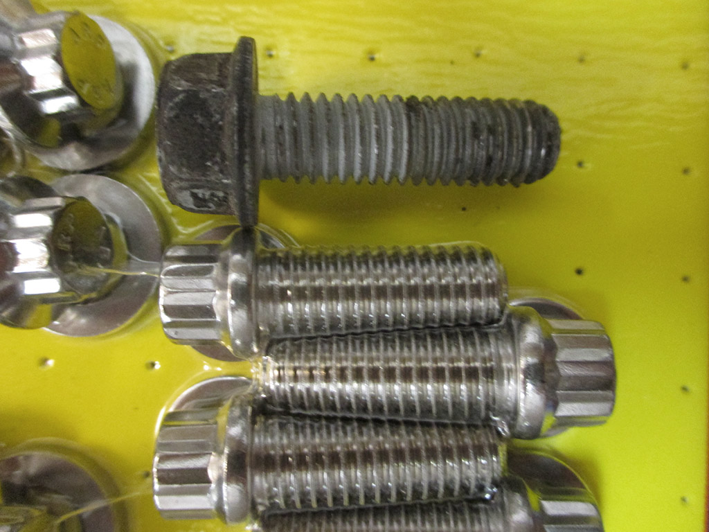
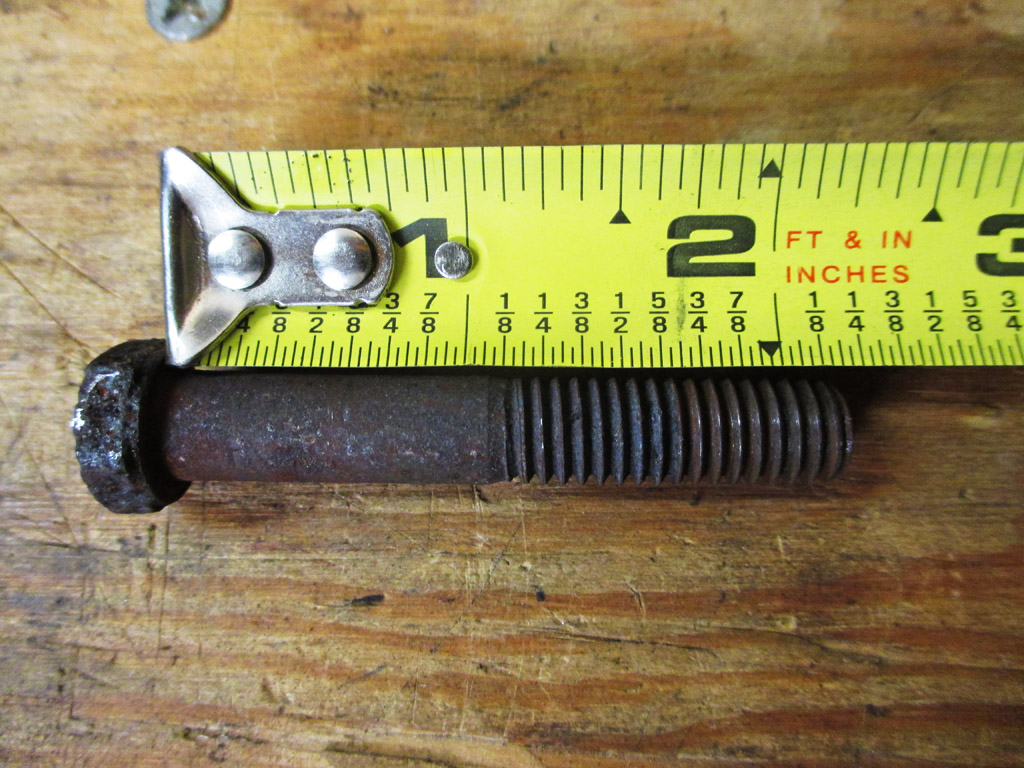
The bolts I received in this kit measured 1" in UHL (under head length), which translates to 1/2 inch thread grip length. The stock bolts are longer at 1 1/4" UHL giving more penetration of the threads at 3/4 inch thread grip length. This left me rather perturbed.
The more I thought this over, the more I felt that the new bolts should be the same length as the OEM bolts. Back on the ARP website, I drilled down deeper and discovered an ARP intake manifold bolt kit for the Big Block 396/454 that is the proper 1 1/4" UHL and is also 3/8-16 RH threads. So I ordered a big block bolt kit for my small block. Simple huh?
These new bolts (435-2101), marketed as BIG BLOCK bolts are exactly the same UHL as the OEM intake manifold bolts for my "small block" 305. The difference between the two kits being noted in the prefix, 434-2101 vs. 435-2101. I should probably mention this to someone over at ARP, since I can't be the only gearhead to run into this.
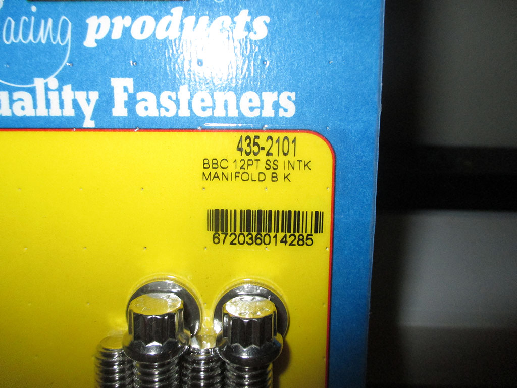
I specifically ordered bolts with a 12 point head due to the tight confines I'm working with. I'm glad I did because they really made a difference. However, in my eagerness to get the intake installed, I neglected to chase the threads out with a tap to make assembly easier. I grabbed the new bolts and went to town.
Naturally the hole we had to chisel the last bolt out of decided to be uncooperative. Simply put, the new bolt would not go in all the way. Adjacent to the heat riser crossover, this bolt hole probably has carbon buildup or plain old corrosion. I didn't want to pull the intake or put an extra washer under one bolt and the 3/8-16 tap was too long to fit. Back on the workbench, I grabbed a "short" intake bolt from my first order from Summit and used it instead. Not such a big mistake after all.
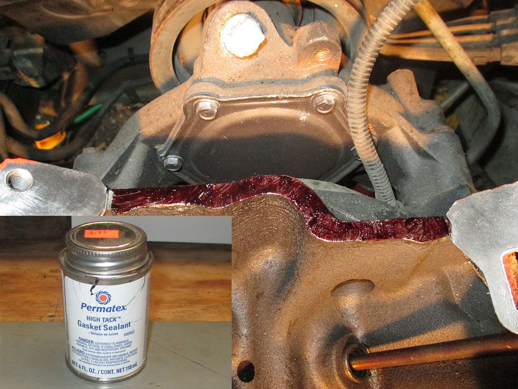
This maroon colored goo is gasket sealant and adhesive. It is some of the tackiest stuff I've ever worked with. I had spider webs of this shit all over the place despite how careful I was trying to be. The directions state "apply a thin even coat to both surfaces, allow to dry for several minutes". Problem 1 - the damned stuff is trying to "dry" at the same time you're trying to apply it! Problem 2 - getting the gaskets to adhere to the block instead of your fingers. Gloves? Who's got time for gloves?
My original plan was to have this accomplished quite some time ago. I bought a gasket set, had the gasket sealant/adhesive, all that was missing was the hardware. I guess that's the price you pay when you're upgrading as you go, instead of replacing all the stock stuff.
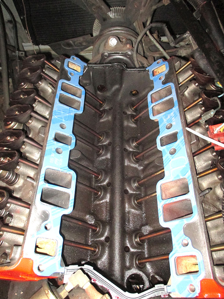
It's been a long time since I've replaced an intake manifold. I laid down both blue manifold gaskets and was wondering how to hold them in place. I forgot that the front and rear rubber gaskets have a molded notch in them that fits the small tab on each manifold gasket. Man, once the mind goes you're sunk.
Exhaust Hardware
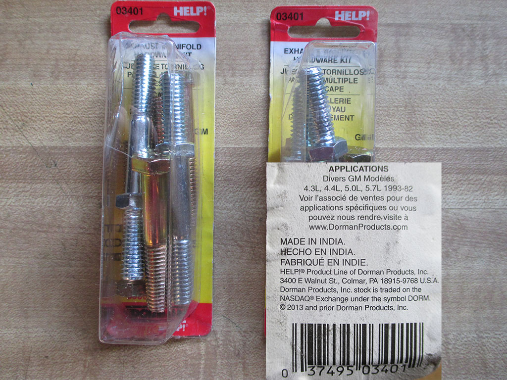
The next problem arose when I decided to get new bolts for my stock exhaust manifolds. Evidently, no one (other than myself) has ever attempted such a thing. Header bolts, no problem, but they are way too short for what I'm doing. The Summit Racing rep helping me eventually found an exhaust manifold hardware kit with 6 bolts/studs where necessary. I ordered two kits. Dumb move on my part.
Made in India. That's beautiful isn't it. The first mental image the word India conjures up? Immense foundries and cutting edge steel production facilities - metallurgy second to none? Uh... no. These will be returned ASAP.
I spent an hour or so on the ARP website and discovered they sell 5 packs of bolts based on thread size/count, under head length, grip range, thread length and overall length in your choice of stainless or black oxide. $20 bucks a pack for stainless, $15 for chrome moly black oxide. I think good quality black oxide bolts will be just fine for my exhaust manifolds. As luck would have it, I measured wrong... again!
I started my research by measuring the old, rusty, pitted, original exhaust manifold bolts. SAE wrenches fit like a slap in the face, metric wrenches are either too small or too big. Each bolt was 2 3/16 inches long with a 1/8 thick washer beneath each bolt head. Why would you make a bolt 3/16 longer than a whole 2 inches? I ordered 2 inch replacement bolts when I probably should have ordered the Black Oxide, 2.250 in. UHL instead.
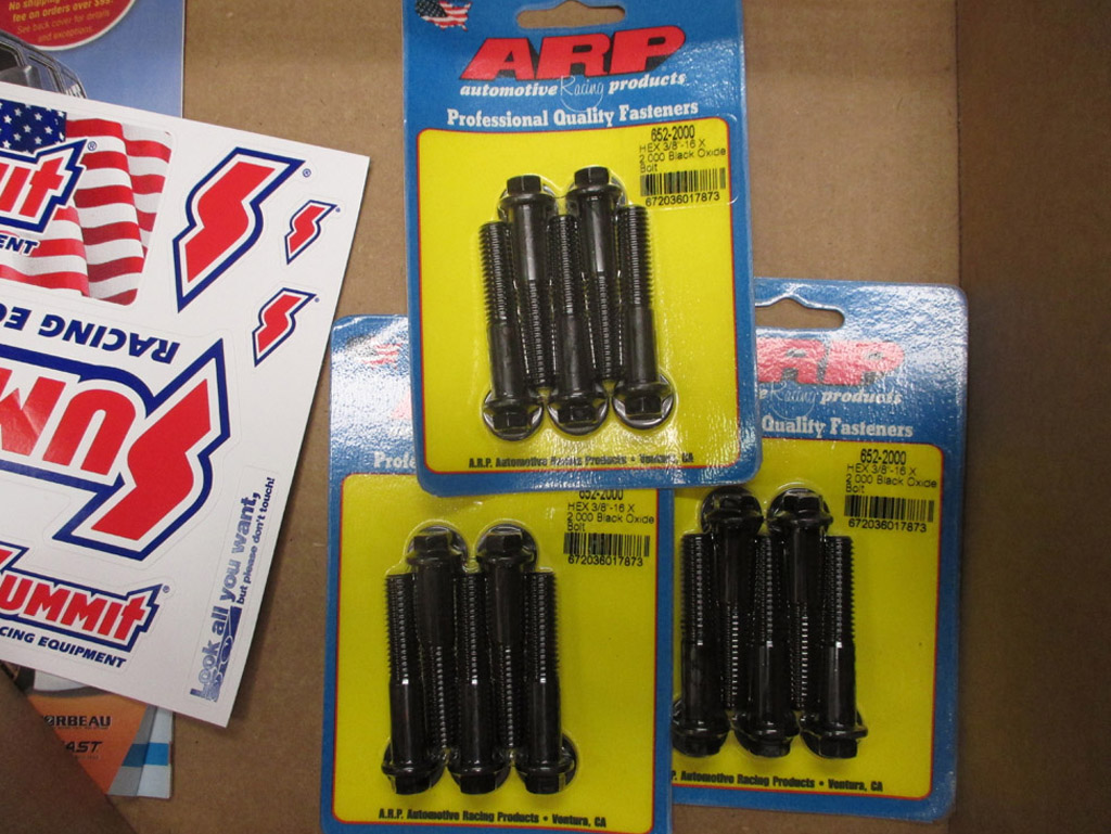
The ARP webpage lists the underhead length in inches using decimal points which threw me off. Once again I ordered bolts that were too short and can only blame myself for this little blunder. Thank goodness Summit has a no hassle return policy. Worse still, I had to order 3 packs of bolts (sold in 5-packs only) to get the 12 bolts I need. This shit keeps up I'll never get the damned engine back together again.
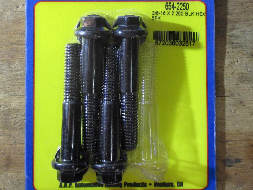
One strike and then a solid hit. I picked up the phone and called my friends at Summit Racing and (once again) ordered 3 five-packs of the size I should have purchased in the first place. ARRRRRGH! If all the OEM bolts had been in good condition (like those few that got caked in engine oil) I'd have simply reused them. Unfortunately most were too corroded to reuse.
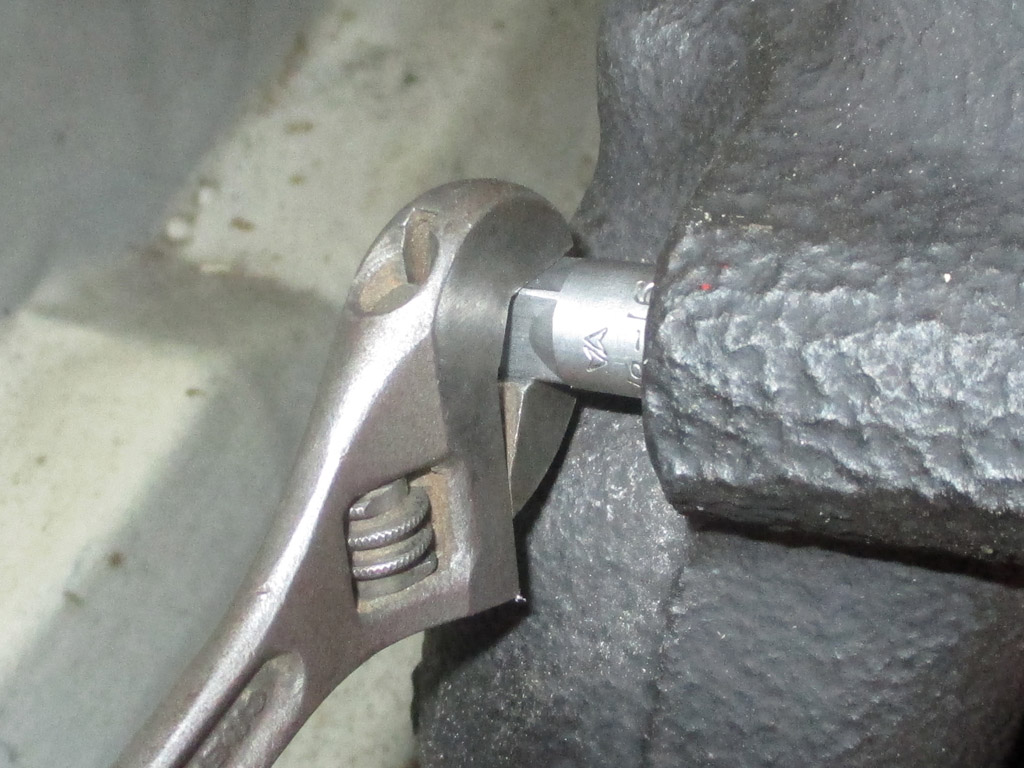
Believe it or not (I find it difficult to believe and I'm the one it happened to), it took me 6 hours of finagling to get this bastard lined up properly! The starter heat shield insisted on getting in the way (it was missing a retaining nut) over and over again. The hot air tins on the manifold were hitting the motor mount unless I wiggled the manifold into just the right position. Then only two of the 6 bolts lined up well enough for me to get them started by hand. To say it tried my patience would be putting it mildly.
Right about then, Murphy stopped by for a visit and the front bolt would not go in all the way. I pulled the stud setup for the opposite side power steering pump mount and checked it against my bolt. The length was identical. My fix was to get my 3/8-16 tap and run it all the way in. Problem solved. It's always the last bolt!
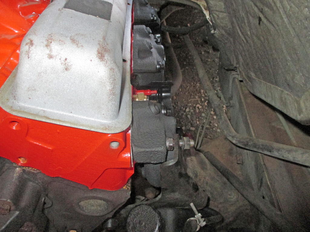
The next day I tackled the driver's side of the engine. After fighting World War III on the passenger side, this side practically fell into place. Every bolt seated fully and I torqued them to spec per my shop manual. The center bolts get 20' pounds of torque, the outer ones get 30' pounds.
While I'm At It... 
With radiator reinstallation on the horizon, I took the opportunity to fix a stupid piece of engineering on my van. I'd really like to meet the guy who thought this one up. The petcock drain points straight down so whenever I drain the radiator, the antifreeze hits the radiator support an inch or so below, splashing all over the place making a huge mess. A kiddie pool might catch most of it. Time to fix that.
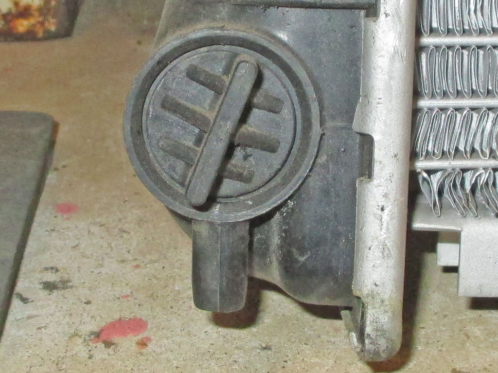
PETCOCK
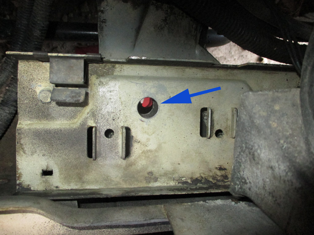
SUPPORT
With the radiator in place but loose, I scribed a mark where I felt the petcock positon over the support. I threaded the radiator out and right in the center of my scribe mark was a hole! It was tiny, maybe 3/32" but it was there for some reason. I used it as a pilot hole and drilled it out to about 9/16" so I could run a hose to the petcock and solve the drainage fiasco. There was a second piece of steel below the radiator support, so I drilled a hole in that too. Once I could see daylight, I knew I was good to go.
August 2017
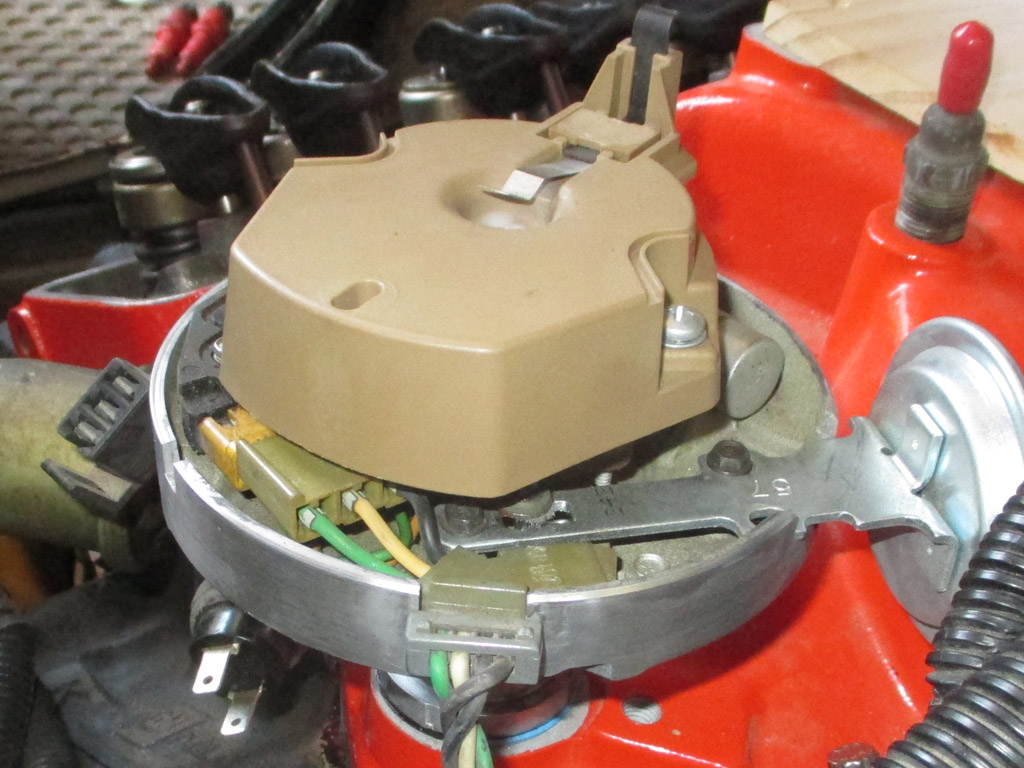
I watched a Youtube video that explained how to reinstall a small block Chevy distributor. You begin with the engine at top dead center. Then, in a nutshell, you line up the vacuum advance with cylinder number 6 and lower the unit in so the rotor ends up pointing at cylinder number 1. Due to the way in which the gears mesh, you actually start lowering it with the rotor pointing at number 3 cylinder and it rotates towards number 1 as you lower the distributor into place.
The video mentioned that the oil pump rod doesn't usually line up but with the distributor/cam gears meshed, the timing won't change as you rotate the engine clockwise by hand until the unit drops in all the way. Unexpectedly, my distributor dropped all the way in! I was stunned. What better proof that you're lined up properly than it dropping right into place? A little semi-gloss VHT black dressed up the hold down clamp and bolt. Damn. Dropped right in. Amazing.
My new aluminum rocker arm covers do not have the built-in wire loom holders that the stock steel coveres had. That meant new wire looms of some sort needed to be procured. I looked at many different styles, eventually settling on the "Made 4 You" brand of horizontal wire loom. Each wire loom is integral with each of the two lower rocker arm cover bolts, which use stainless steel allen head cap screws. I wanted a clean uncluttered look, so going over the covers was not an option. I'm not sure how well these will work, but they seemed like the best solution and were USA made.
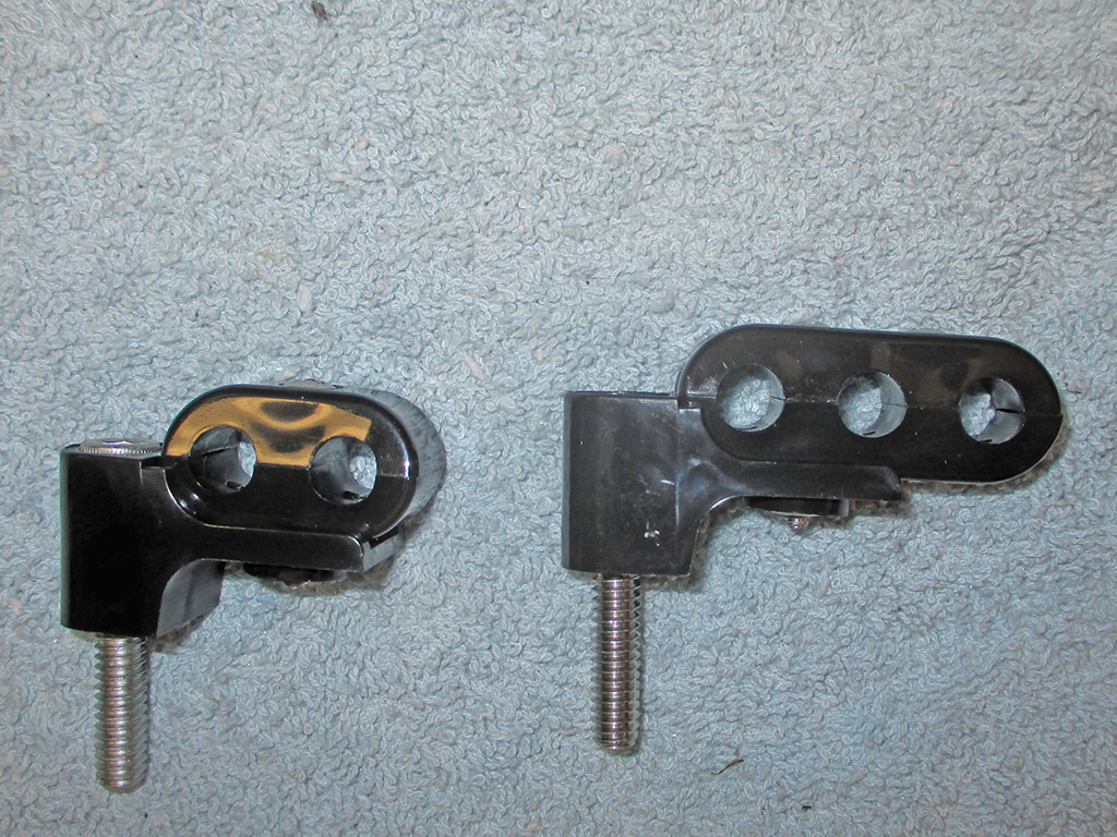
Wire Holders
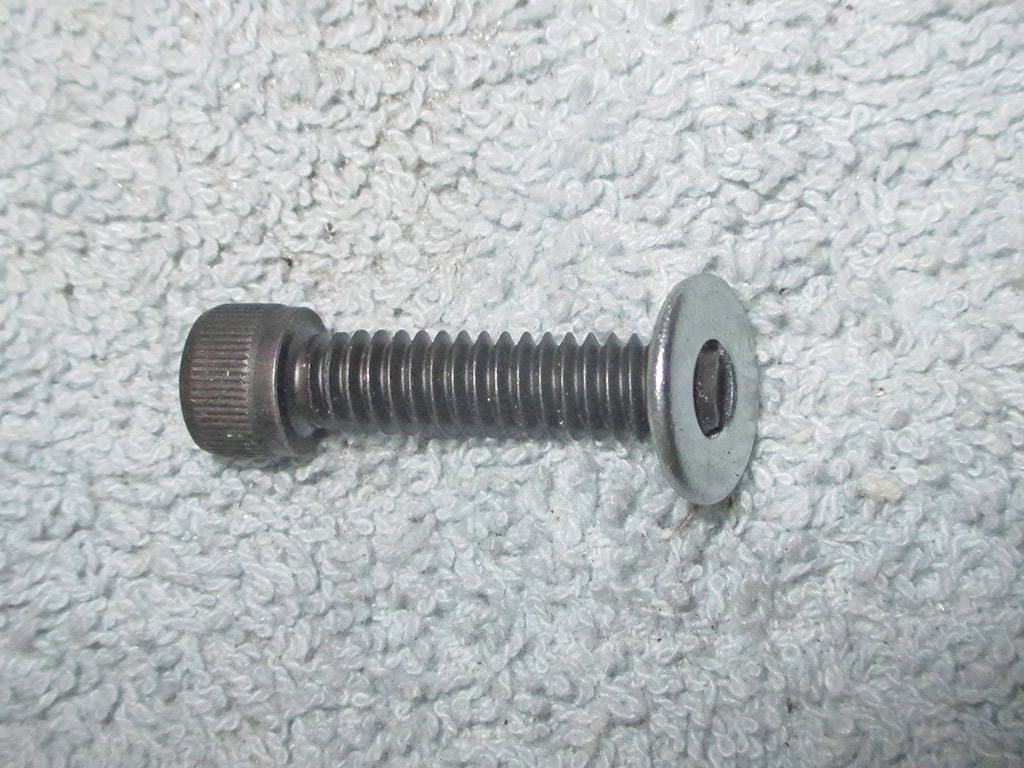
Washers
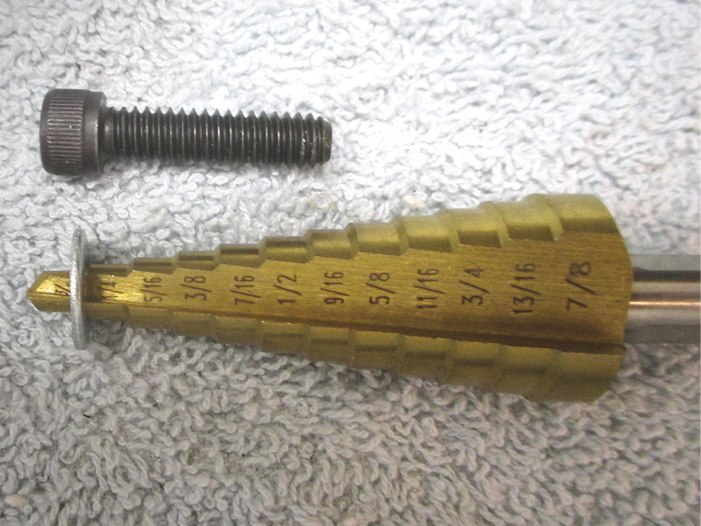
Size
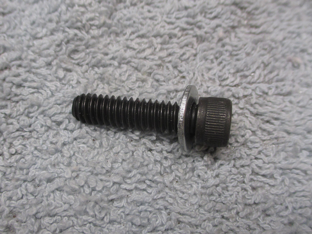
Done
Eventually, I'll order some stainless steel cap screws from Summit Racing, but for now I want to get this thing fired up, so I cobbled some stuff together. Yeah, it's a lot of extra effort, but when I picked up these cap screws at my local auto parts emporium, the SAE washers were too small or too big for my application. I bought some metric washers and modified them to fit.
Then I attempted to install the carburetor. Here's the scenario. It's late in the day, I'm tired but figure I'll finish one last thing before closing up shop for the day. I should have waited. I assumed (big mistake) that there would be no problem whatsoever in bolting the carb onto my shiny new intake. Can you see where this is headed yet? I could have waited until the following day to make a fresh start. But I didn't. I've been doing this a long time and still haven't learned.
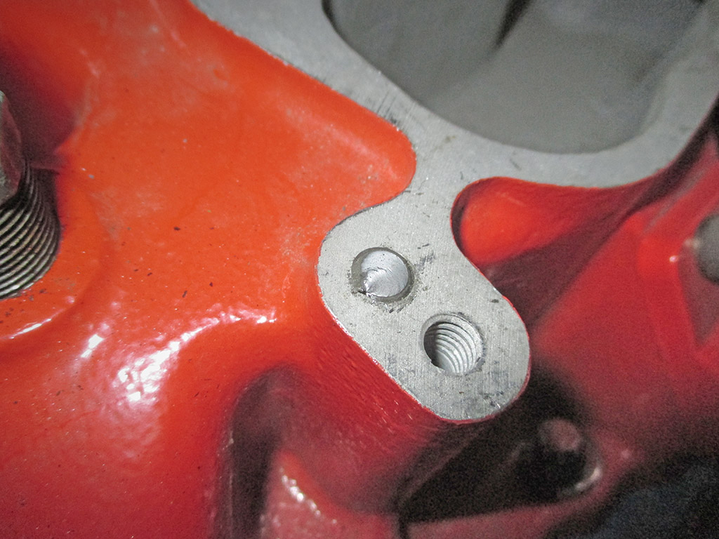
MANIFOLD
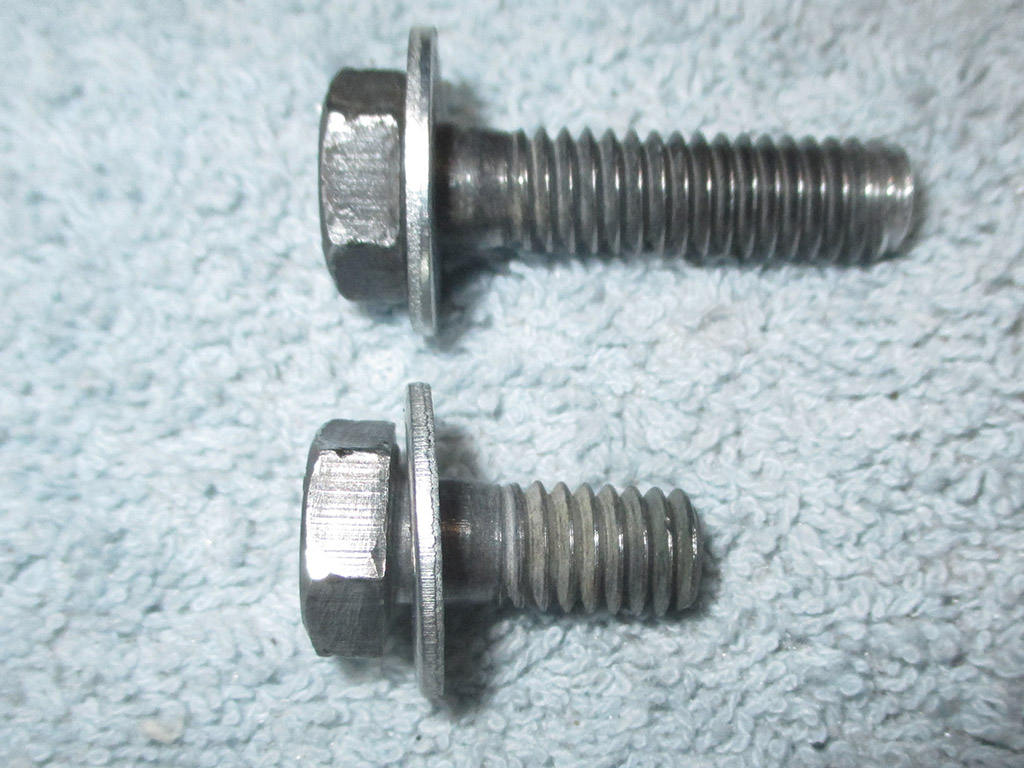
BOLTS
One rear bolt of the carb went right in, but the second started binding up. Did I reverse gears and take the bolt out? No. I went into my toolbox and got a breaker bar to put over the ratchet handle. It worked perfectly... I broke the bolt off in the manifold. At that point I put everything away and went upstairs.
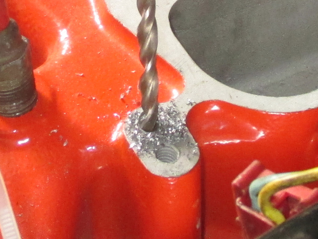
I've been down this road before, so I was prepared for just such an emergency. I went digging in my tool box and discovered that I had just the size Helicoil that I needed to fix this little setback. Step number one, get a center punch and mark the center of the bolt. Accuracy counts. Then grab your drill and get to work. Ideally, the ultimate objective is to get your bit perfectly centered so you drill out the bolt and leave the threads behind. Evidently Edelbrock doesn't drill their holes as deep as the OEM did on the intake, so I still had to find shorter bolts to use to mount the carb.
The Helicoil kit comes with an installation tool, a special tap and several sets of coil inserts. The kit requires a specific size drill bit (purchased separately) matched to the tap. Unless you have been a machinist for the past 40 years or so, you will not have this size in your toolbox. I live near an old fashioned hardware store that still sells USA made bits in all sorts of sizes. In fact, I store this specially sized drill bit with the Helicoil kit just so I don't ruin it drilling an "ordinary" hole somewhere else!
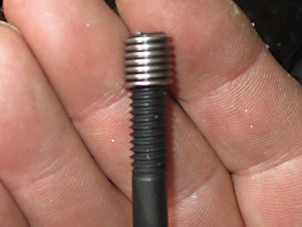
Mounted
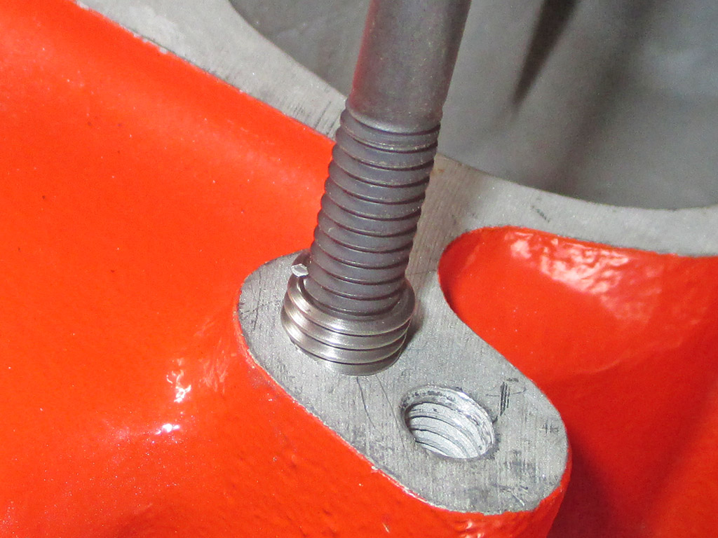
Going In
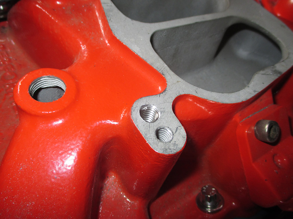
Done
So you drill your hole and remove all of the metal shavings. Do your level best to get the tap started as perpendicular to the manifold as possible. Mount a Helicoil insert onto the installation tool and thread into place. Using a punch narrower than your newly installed threads, tap the punch to break off the installation tab and the repair is finished. Following this, I ran a regular tap in all three of the remaining bolt holes just to be on the safe side.
Now, what have we here? This is the spacer that goes beneath the air cleaner on my van. What's it doing here? In order to plan how I'm going to run my wiring and hoses now that I've made several changes, I need to install the air cleaner assembly since it requires the most space. I cannot install the air cleaner assembly without first installing this spacer. Naturally, it was nowhere to be found. This is emblematic of how I end up working despite my best efforts to stay organized. I work up to the point where I am missing a key part, and all progress comes to a screeching halt. This typically results in an extensive (not to mention frustrating) parts search. Happens to me all the time.
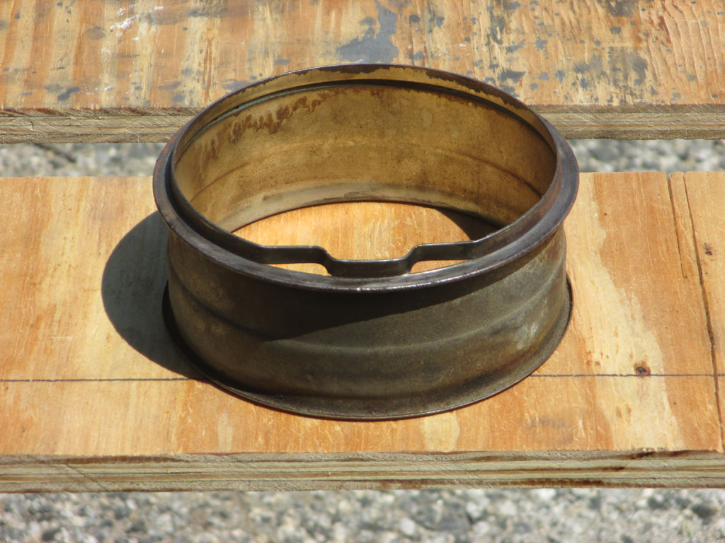
BASTARD
LIVES HERE
It was the end of the day and I wanted to install the air cleaner assembly before closing up shop for the day. Nope. Not happening. The carb spacer seen here was nowhere to be found. It wasn't in the van. It wasn't in my workshop. It wasn't on the shelves where I store all my van stuff. The next day, following a frustrating three hour search, I finally found the damned thing in (of all places), an open box full of clothes hangers! I have no idea how it ended up there.
The OEM air cleaner didn't even have a 2 inch snorkel opening! Way too tiny to feed a four-barrel carb in my opinion. An open-element air cleaner would look cool, but the last one I ordered from Summit was made in China, so I returned it. The new assembly came off a junkyard van about 8 years newer. I grabbed the whole shebang (including the fresh air tube), for ten bucks. Since it is significantly larger, in encroaches on lots of other "stuff."
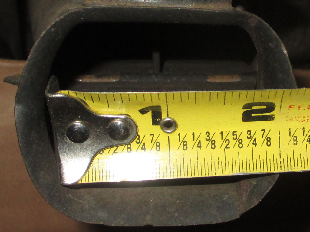
OEM SNORKEL
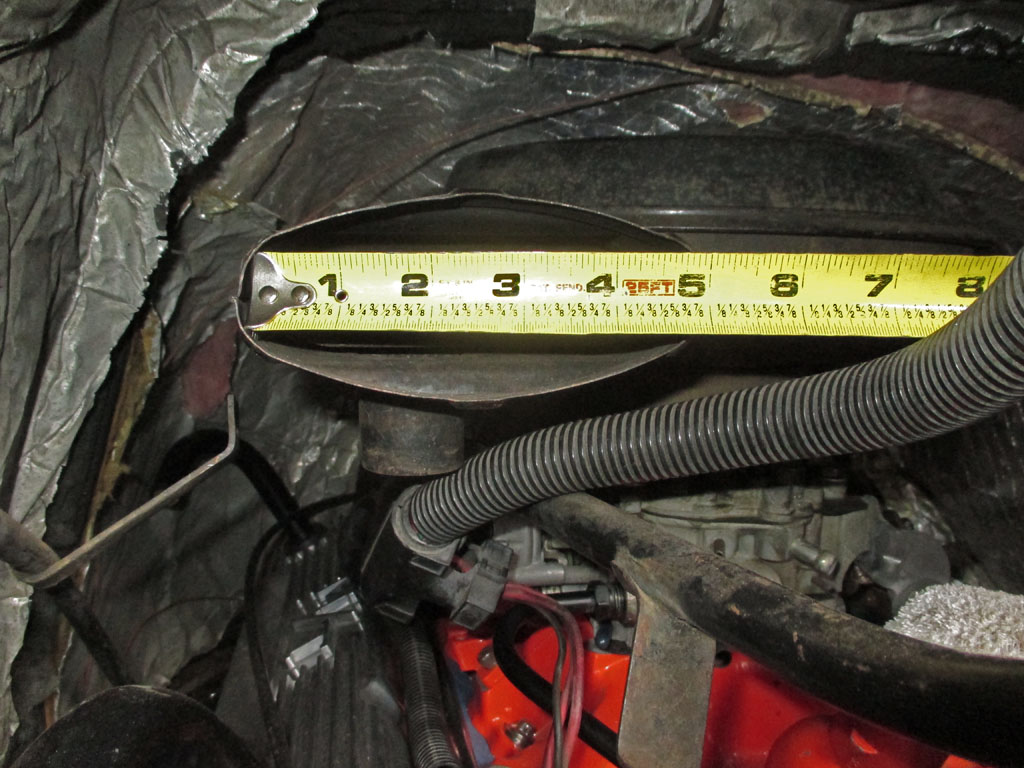
NEW MODEL
It has a larger (roughly a 5"x2" oval opening) snorkel and a fresh air intake so the engine could breath cool air from behind the grille instead of hot, under-hood air. This should result in enhanced engine performance and the little 305 needs all the help it can get. It does moan now when you get on it, but so would an open element from the 60's... before noise regulations put the kibosh on OEM units.
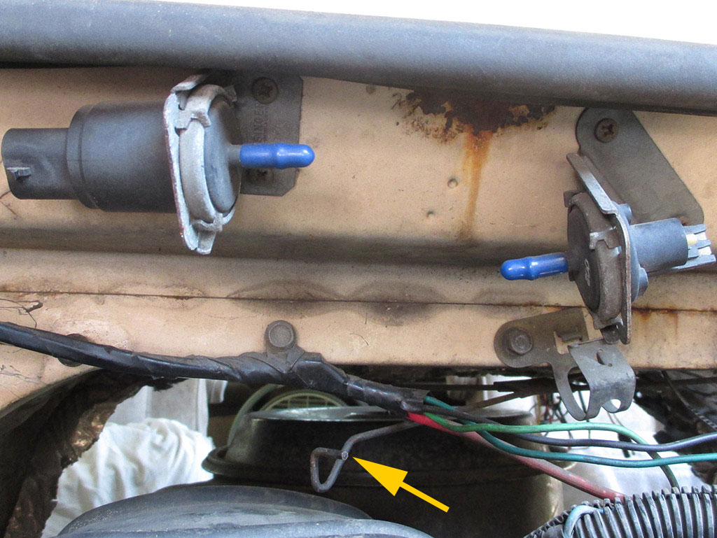
I have no idea what these are. I've done image searches online and can't find any information. I scoured my shop manual as well, but no mention is made of these. My theory is they were part of a device associated with the air conditioning, since they are quite close to a rod that is currently hanging in space (arrow). When I move the rod, it sounds/feels like it's connected to a flapper door inside the van. Pure supposition on my part of course.
Each of these "units" had a two wire "Weather Pack" electrical hookup as well as a vacuum line connection. No vacuum lines were present when I brought the van home. The unit on the left had a wire loom running up from the passenger side rocker arm loom all the way up to this little device. Emphasis on the word had. In my quest for space to reconfigure the fresh air intake et.al. I decided the electrical connections and these two "whatever-they-are's" all needed to go. Pass me the diagonal cutters please.
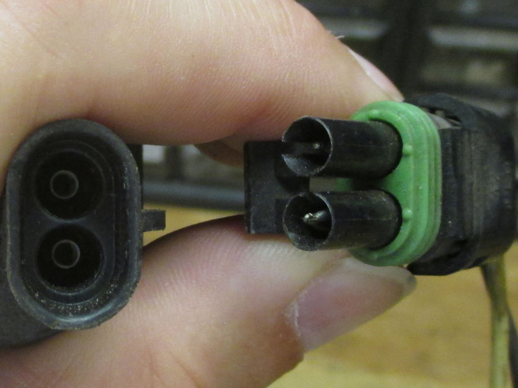
A Weather Pack connector is manufactured of nylon plastic and has silicone seals to prevent moisture and dust ingress. These things are really pretty clever, as each connector has a locking mechanism that aligns the terminal and seal, and is indexed to prevent mis-mating. That's good to know if you happen to disconnect a bunch of them and (in the heat of the moment), don't bother to stop and label everything. Not that I would ever do such an amateurish thing myself mind you.
Since I'm not sure whether or not I will ever need these wires again in the future, I made sure to leave enough slack so soldering them back together would be easy. To prevent short circuits, I stagger the cut of each wire lessening the chance they'll short out later. As anal-retentive as I tend to be, I also sealed each wire with heat shrink.
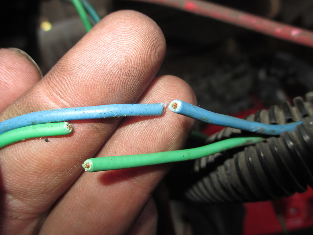
STAGGER CUT
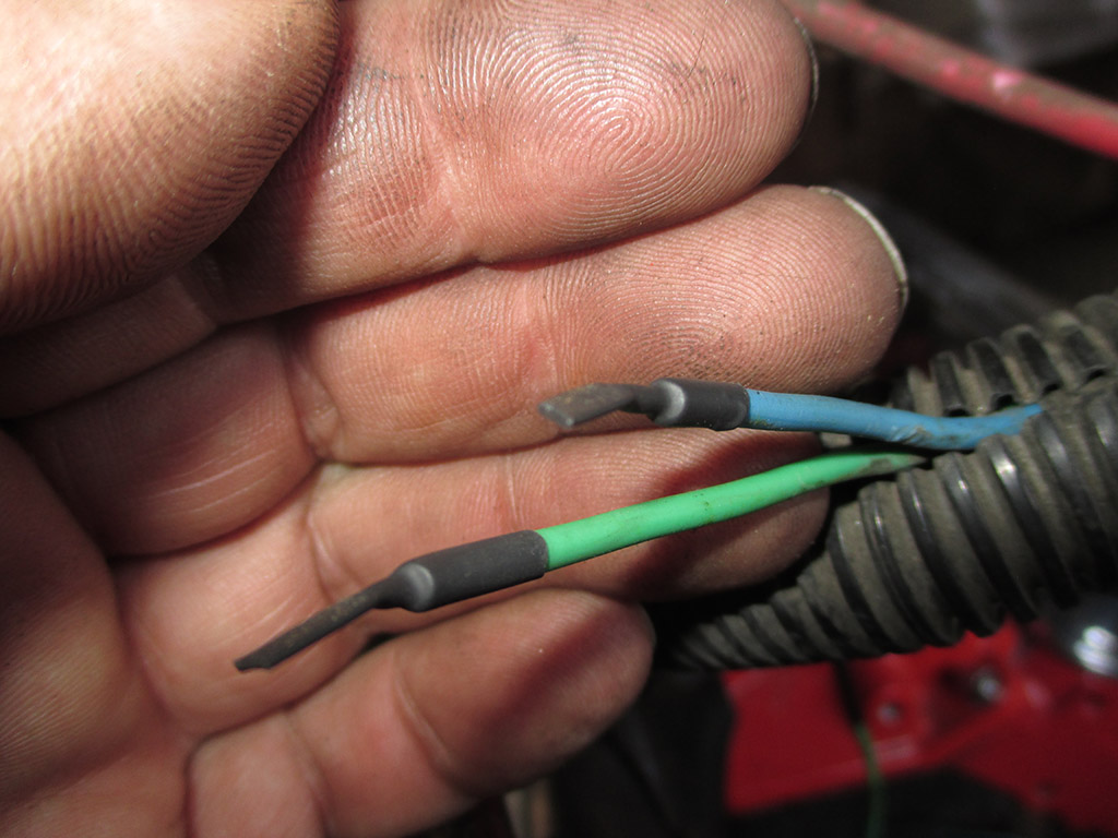
HEAT SHRINK
As soon as I set down my heat gun I picked up my needle-nose pliers and using the smooth part of the jaws carefully crimped the ends of the heat shrink shut. Then I tucked the wires back into the split loom they originally came out of, electrical taped the area and called it done. I'm pretty confident the wires won't short out or corrode from moisture. I duplicated this process for both wire harnesses here as well as the harness that once powered the AIR valve.
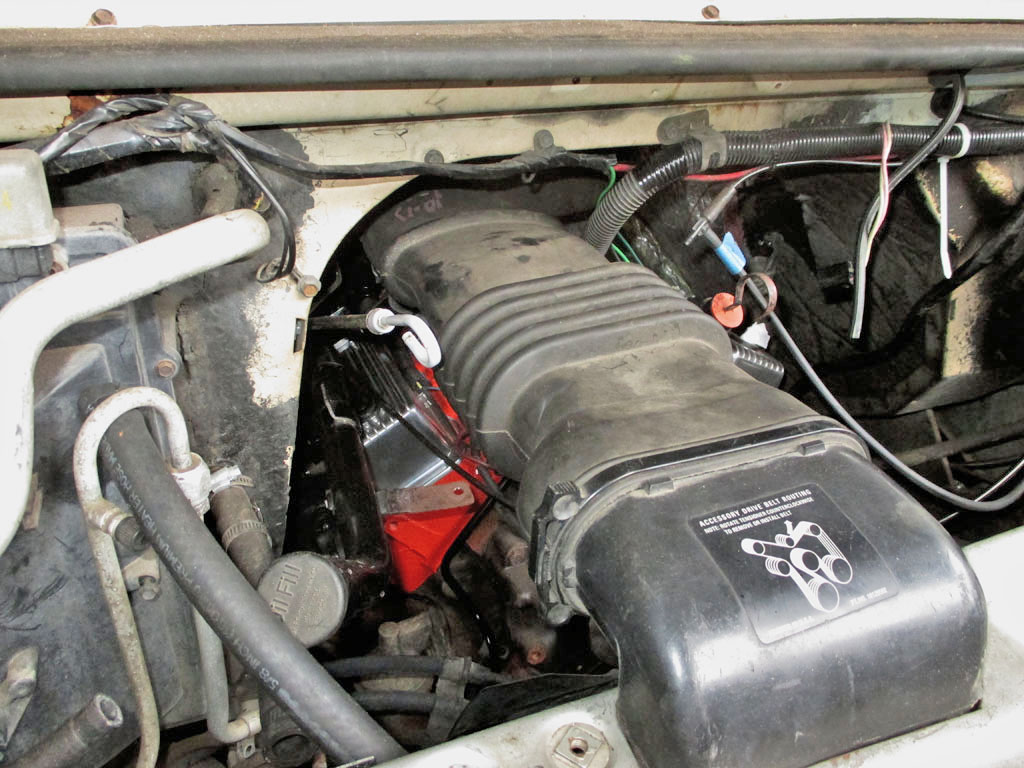
With the new fresh air intake, oil fill tube, oil dipstick and transmission dipstick all loosely in place it was time to duck back inside and figure out how I want to run the wire looms to the alternator. I want to keep them up off my rocker covers. Then I can install the hard line from the fuel pump to the carb and install the alternator. Once I get everything to fit, then I get to figure out how to support all the brackets that no longer bolt up together.
On a positive note, the new rocker arm covers have already repositioned the oil filler tube and there is some flexibility in the dipstick tubes, so everything should fit, including the A/C manifold hose lurking in my shop. A large part of the process for me is staring at the problem. Assessing whether I can use the existing support bracket, modify it or create a whole new bracket really eats up the clock.
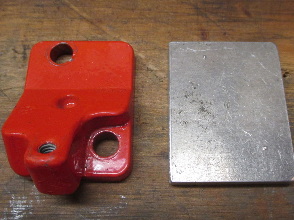
Instead of fabbing up a new block off plate, I noticed that the EGR block off plate on the Edelbrock intake had a raised threaded boss that tuned out to be the answer to my wire loom neatening project. I found a cap screw that fit the threaded boss so I decided to use what I had at my disposal.
I took an ordinary cable clamp, removed the rubber lining and reshaped it around a 5/8 socket. I spaced it so that once I mounted it to the EGR plate boss it would hold the wire loom out of the way. This took quite a while as I'd make an adjustment, test fit the clamp, then repeat the process until I had it fitting the way I wanted.
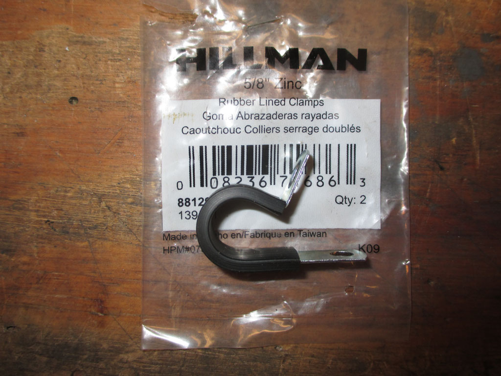
CLAMP
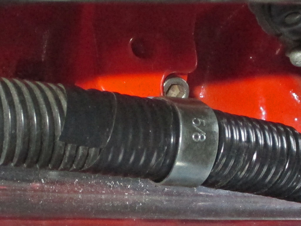
MODDED
In my quest to clean up this part of the engine bay, one thing that helped was my decision to move the smaller of the two wire looms. It originally had three wires, two of which have been eliminated. The remaining wire goes down to a knock sensor low on the engine block. I threaded the wire loom out and then back in from the rear of the engine (behind the starter), which let me clean things up significantly.
November 2017
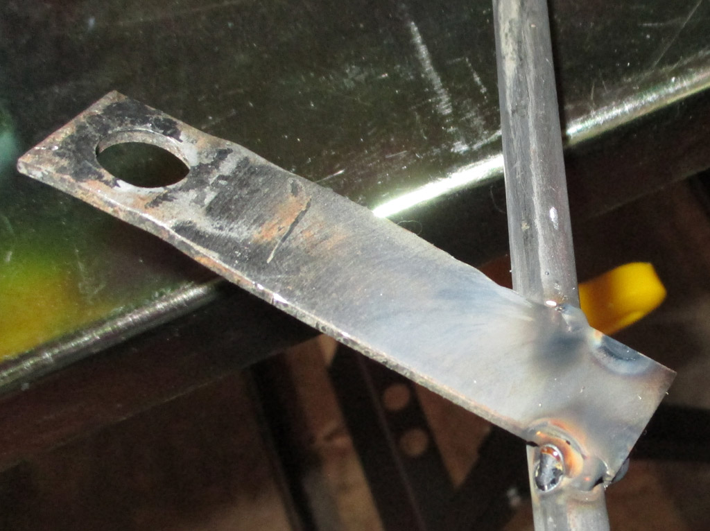
We cut off the original dipstick bracket and then welded it into its new position. I learned that the technique is to start the weld on the bracket and move it onto the dipstick tubing. The factory bracket curved around the dipstick tube and was attached with two spot welds. I used a cut off wheel to carefully grind away the original welds and removed the curved piece. A little work with the Dremel made it so you couldn't tell where the original bracket was.
After some judicious bending of the transmission dipstick/fill tube we were able to route it to the right side of the fresh air intake. It just clears the electric choke, but required extending the original bracket to gain the needed clearance. We added about an inch and a half to the factory bracket to gain the clearance needed.
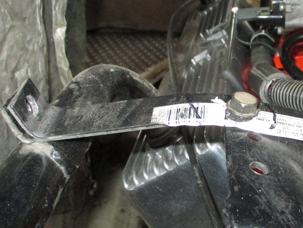
Installation of my new aluminum rocker arm covers necessitated fabrication of a new bracket to hold the oil fill tube in its new location. We clamped some steel stock in the vice and cold bent it with a hammer. With just a propane torch in my tool arsenal, this was the only way to do it short of welding on a section instead of bending the steel like we did. The bend we made is so close to the factory bent bracket this mates up with, we called it done.
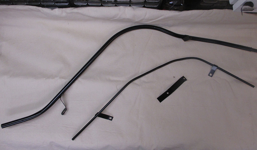
I had accidentally crushed a small area of the oil dipstick with a pry bar some time ago. Don't ask. I took this opportunity to fix my crass mistake. I broke out my propane torch, heated the tubing until it was cherry red and used a small ball pein hammer with some gentle tapping to try and remove the dent from the steel tubing. It took several tries but in the end I got about 90% of the dent removed, enough that the dipstick now slides through the tubing almost as easy as it did originally.
Any time you do any welding it pays to have clean metal to weld, so any paint gets ground off with (in this case), a die grinder and a 2" 120 grit sanding disc. Of course my torch and hammer work burned off all the paint on the section I re-worked. After dressing the welds, I finished up by hand sanding the whole length with some 120 grit sandpaper. I finished everything off by trying out VHT's epoxy semi gloss (spray bomb) black paint.
The only modification necessary to the transmission dipstick (after our initial bending that is), was to lengthen the OEM bracket by roughly 1.5 inches. This raised the tube enough to allow it to clear the electric choke on the side of the carburetor.
Longer
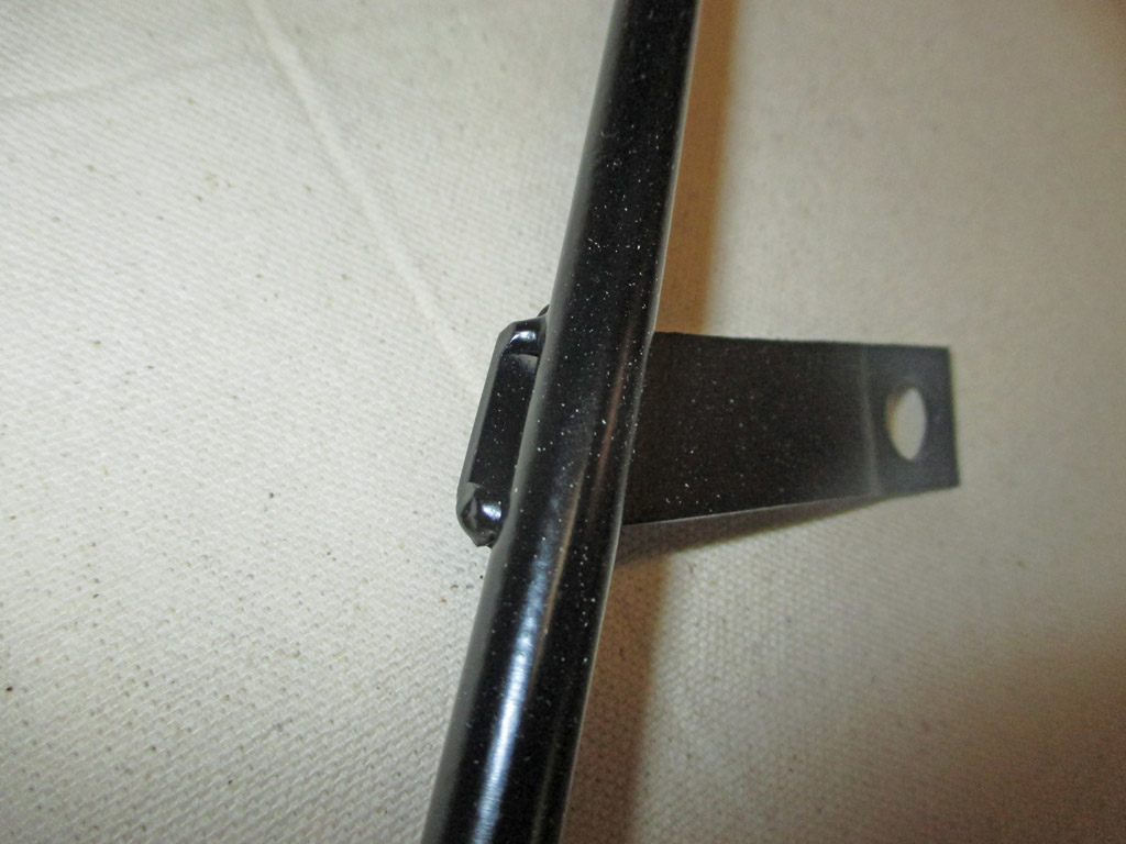
Repositioned
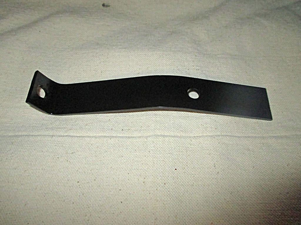
Created
I let all the parts cure for about 4 days. What looks like specks in the black paint is just some sawdust from another project I squeezed in one night after work. I simply blew the dust off prior to installation
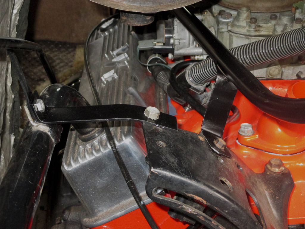
And this is the final result. All bracketry is in place and bolted down. The big question though will be if there is enough room left for the all important A/C hoses. Right now i want to just get the van running again. Once I've accomplished that, then I can work on adding all the other equipment.
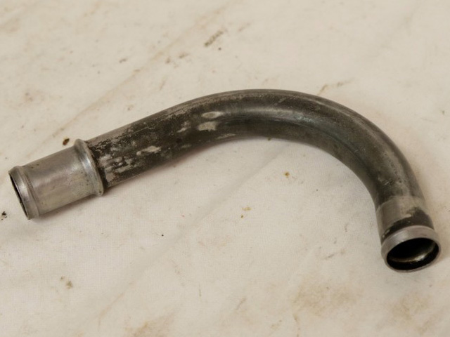
When I bought my van the valve cover vent grommet had a short piece of steel tubing jammed in it and a length of rubber hose running up to the air cleaner. I decided to fix this the "right" way. I took the factory vent tube from another 305 but it had such a sharp bend it was useless for what I was attempting. That meant either a trip to the junkyard or Ebay. In the end I took a different approach entirely.
This is the transmission dipstick/filler tube from my blue Monte Carlo. On a whim, I grabbed it and did a test fit in the grommet of my new aluminum valve cover. It was a perfect fit. That meant I now had an alternative and the shape of the bend in this tube was roughly 45* meaning it actually pointed up at the air cleaner. Immediately I saw the solution to my little conundrum. I decided to use the trans dipstick tube and splice on the original end pieces of the factory vent tube that was useless in its current configuration. Sounds easy when you're standing there imagining solutions to these custom fitment issues.
We took a length of coat hanger and bent it to bridge the gap between the valve cover and air cleaner. We used this as a model which we attempted to match to one of the two bends in the trans dipstick tube. One bend was way too tight a radius, but the second bend was almost what we needed. You know what they say about almost... only counts in horseshoes and hand-grenades.
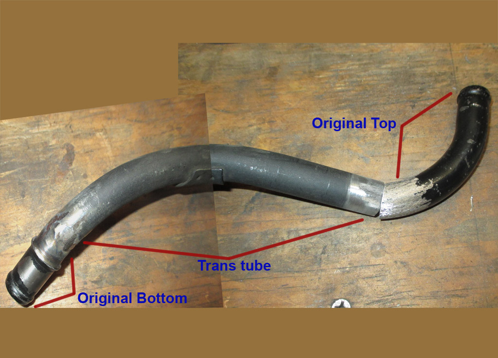
GENERAL PLAN
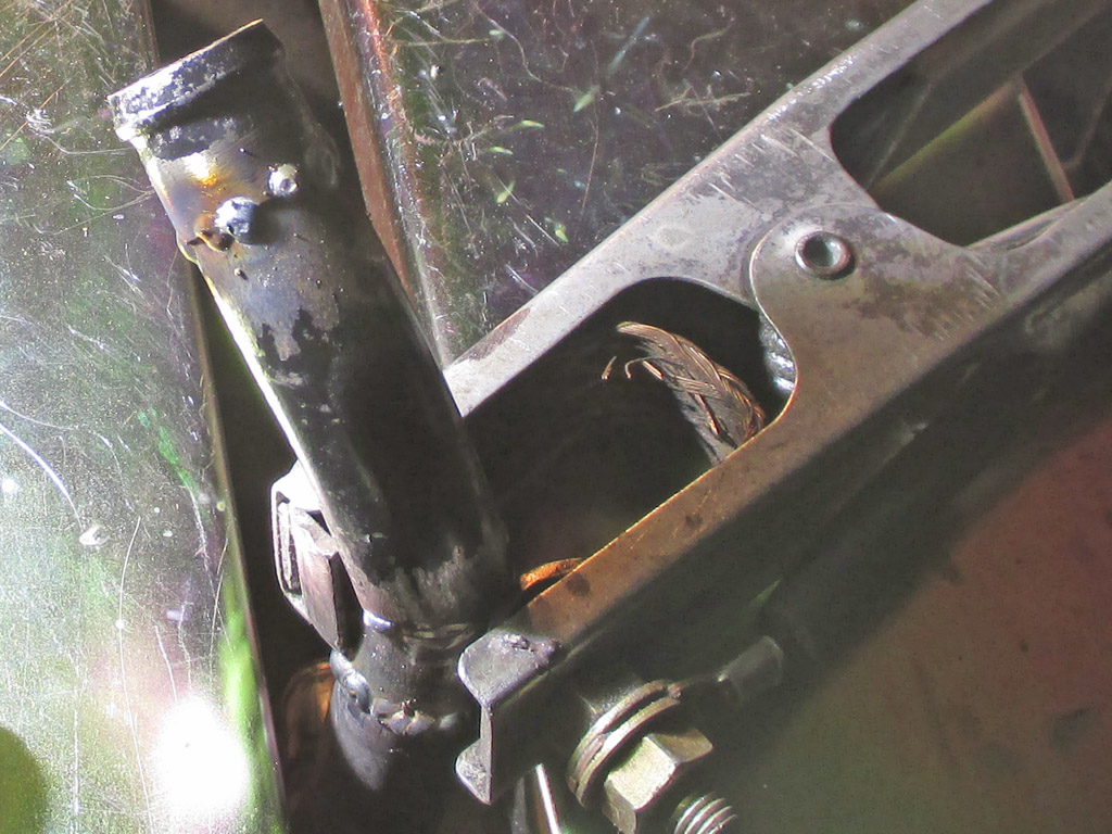
MORE SPLICING
What seemed to be a relatively simple cut and weld job quickly morphed into a major league sectioning project. More than once we had to cut a section out of the air cleaner end to move the tube away from the dog-house engine cover to make it tighter to the engine. Then we didn't have a straight shot at the air cleaner port so we had to cut the tube just above the valve cover and add in a section to lengthen the tube. What took only minutes to imagine took hours in the real world of fabrication.
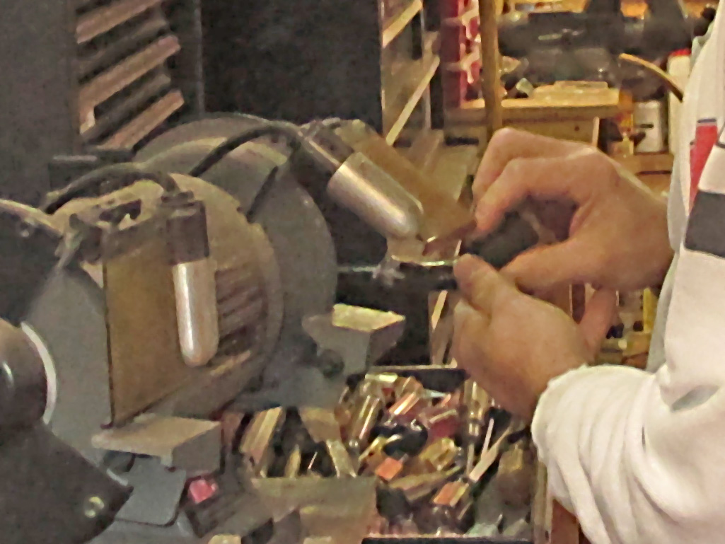
Of course welding in the new sections in only step one in the process. Step two, dressing the weld helps you see if you have welded everything with no gaps, pinholes or low spots. Since the welds are much harder than the steel of what we are welding, so this means some heavy duty grinding is involved. I don't usually go for the bench grinder as I find it easier to clamp the work down and move the tool over the targeted area. My FIL is used to using the bench grinder, so I followed suit.
One of the last things we did on day one was to remove the original support bracket. It's in the way for what we're working on so it needed to go. Our weapon of choice this time was a 3/16 drill bit. Some careful drilling at low speed enabled us to cut through the factory weld without going through the tube. That would be bad. In the end, the bracket-ectomy was a success and I can probably spot weld it to another item in the future.
At the end of the day this is where we ended up. Six hours and it's still not completely finished. Part of the problem (if you want to call it that) is that for each adjustment you make to one end of the tube, you run the risk of throwing some other angle out of whack. So you go out to the van, make some measurements, make some marks on the tube, come back inside, make changes, re-check the fit.
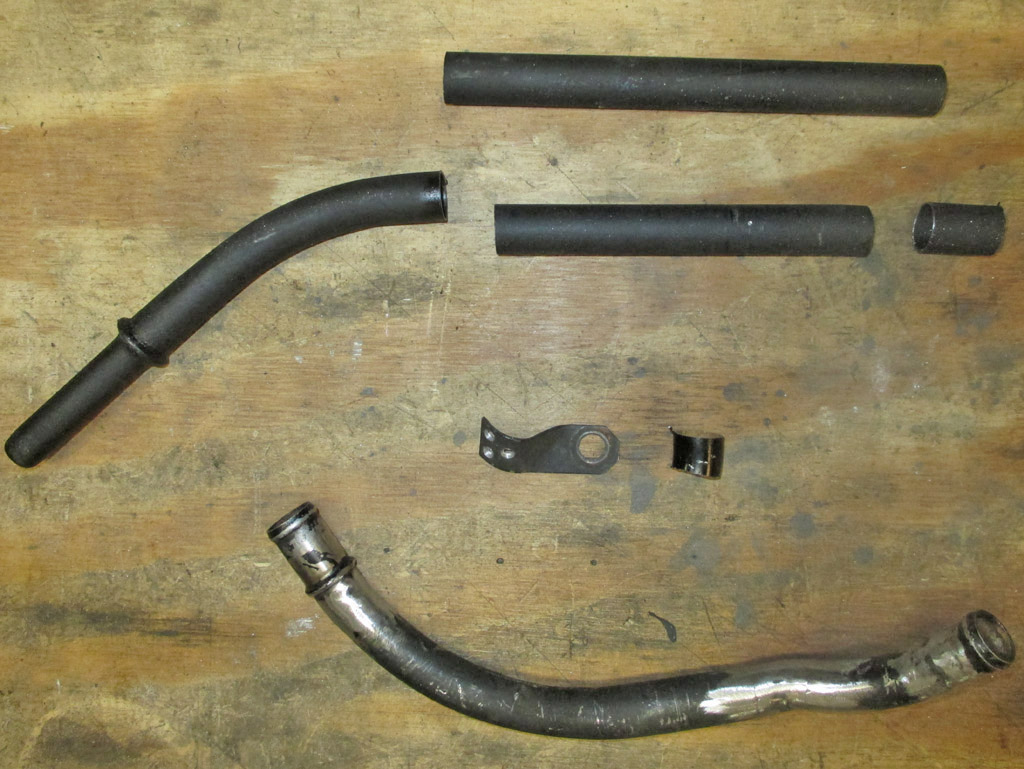
SLICE 'N DICE
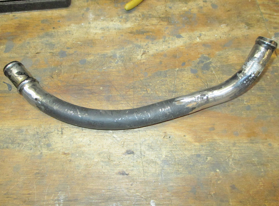
RESULT THUS FAR
Back and forth, back and forth, ad nauseum. The only thing that keeps me motivated is that this little task will never be as "easy" as it is right now. I don't need the van to back and forth to work and I'm not playing beat-the-clock trying to get to a car show. I sincerely hope that all this effort is worth it in the end. Anything will be an improvement over the big ugly hose rubbing against the engine compartment cover.
Day 2
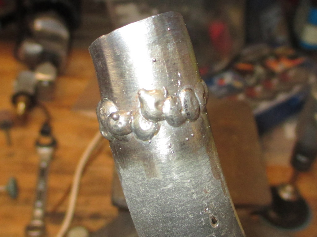
I began day two by cutting the straight section just above the rocker arm cover. I attached the upper end of the tube to the air cleaner and the lower end to the grommet in the valve cover. I positioned the tube where I thought it should go and measured the gap between the two sections. I discovered I had a small slightly curved section of tube that would fit just right. Being slightly curved meant the tube began its angle towards the air cleaner sooner, resulting in a more compact install. I made an alignment mark on each piece and clamped the work in my vice. I worked my way around the tube, laying down tack welds as I went along.
I have learned that setting up my welder for a job is just like setting up my table saw or any other tool. I started out by loading a spool of .023 wire for the type of work I'm doing here. Comparing the thickness of the metal I was working with to the settings chart on the inside of the welder's door comes next. The factory recommendations regarding the heat and wire speed of the welder are usually a good starting point. I discovered I do a better job when making one tack weld after another while the steel is still hot from the previous tack. This isn't always possible particularly as in this instance where you have to rotate your work frequently.
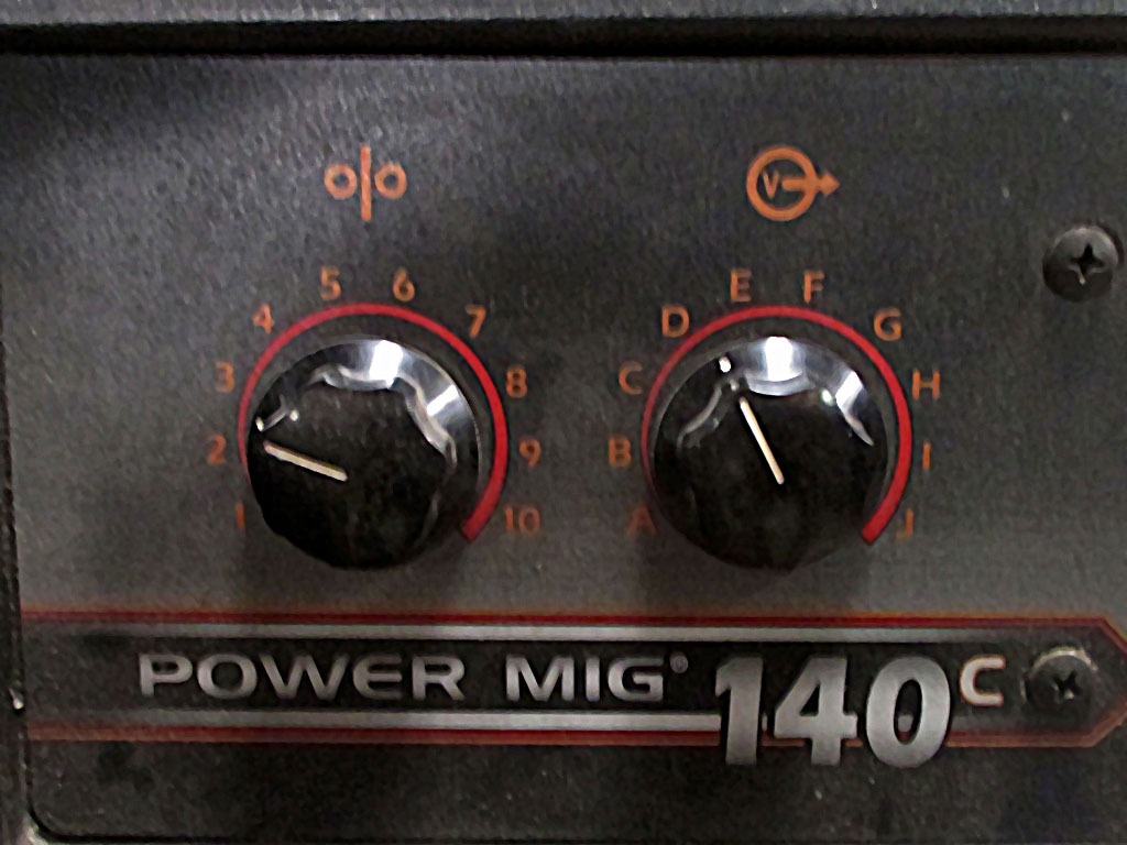
DAY 2 HEAT/SPEED
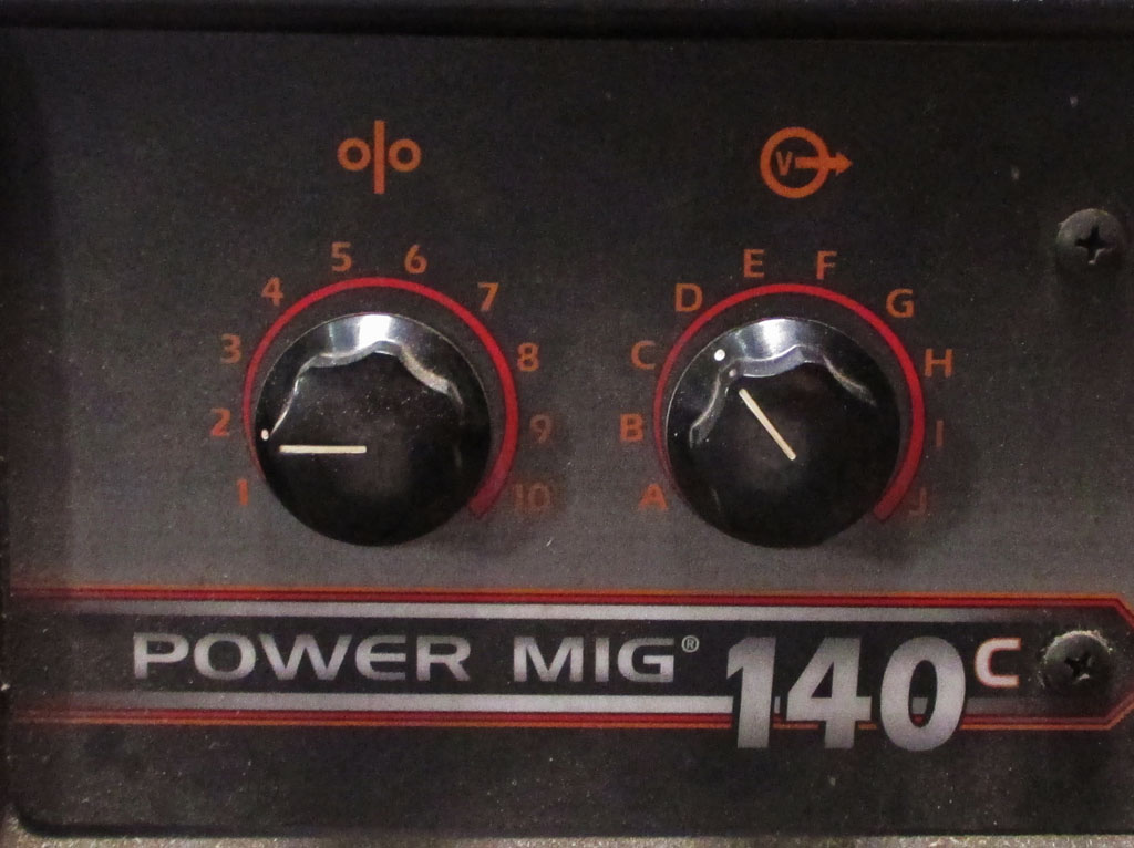
DAY 3 HEAT/SPEED
Day 3 found me melting holes in the steel. I lowered the heat setting to the letter D and wire speed to 2 for my next session. I found that with the new settings if I held the trigger for a 2 count and hit the splice between both sections of steel tubing, I would get good penetration and not blow holes in the tubing. I am learning to be consistant with my welding, same length stinger sticking out, hold the torch head the same distance and angle each time and hold the trigger for the same amount of time for each tack.
When I mocked up the air cleaner end of the tube, it fit better measuring the tube against the body of the air cleaner vs. the plastic fitting. It was only an inch off, so I cut out the length I needed. Of course, once you remove a section of the tubing you need to weld the two ends back together again.
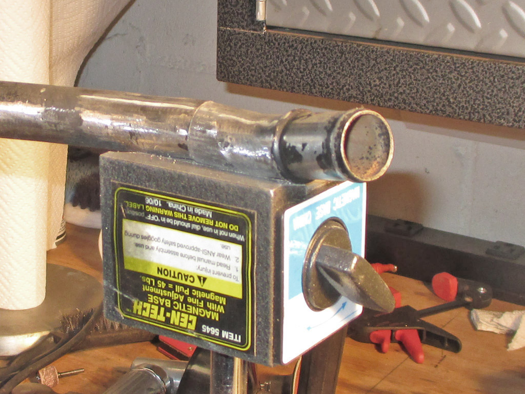
MAGNETIC HOLDER
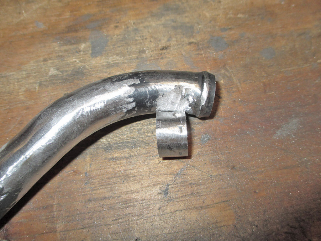
REMOVED SECTION
I needed a way to hold the two pieces in alignment and ended up using the magnetic base of an articulating arm holder from Harbor Freight. I inverted the magnetic base, clamped it in my vice and the indented center of the base held the tubing in alignment. Two tack welds later I was able to move from the magnet to the regular vice, rotating the tubing as I worked my way around with the welding torch.
This was supposed to be done now. But NOOOOOOOO! Despite my careful measurements while holding both halves in position earlier, I'm still not there. The stupid tube is still too short and the angle of the end that mates up with the air cleaner is going uphill.
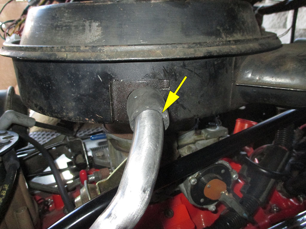
STEP 8
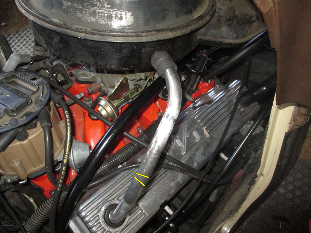
ADD PIE CUT
Back to the old drawing board... once again. The yellow arrow denotes that the pipe is pulling down on the hose that connects the upper end of the tube. That means it's too short AND the end going into the rubber hose is not level like it needs to be. I will attempt to insert a "Pie Cut" as illustrated above. Will this be the last section I need to add? I certainly hope so.
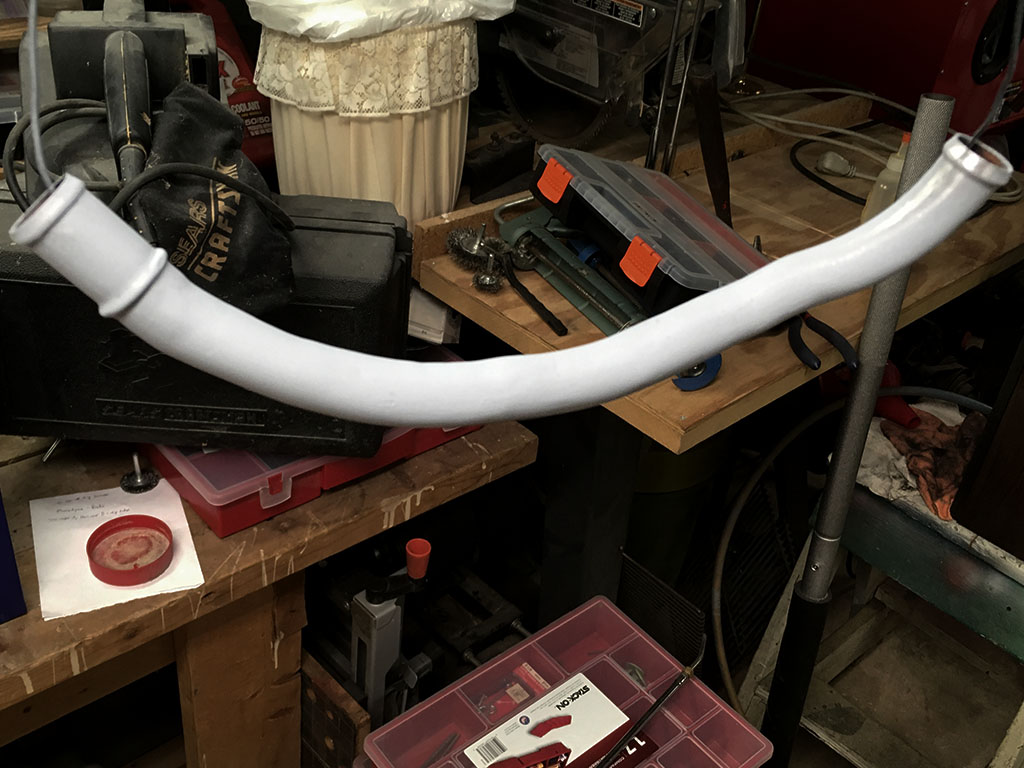
The last section added finally got the breather tube aligned to my satisfaction. I could clown this up with tales of holes burned through the tubing and the necessity of fixing those as I moved along. That's ok though, I'm learning plenty as I move along with the project. I discovered previously that rattle can paint does not hold up very well, in some cases allowing rust to show through in short order. In an attempt to overcome this situation, I've prepared the surface with 150 grit, wiped it with 70% alcohol until the paper towel was clean and then given each piece 2 light coats of VHT primer followed by one medium coat per the instructions on the can. My next step will be to scuff the primer with an abrasive pad and shoot it with VHT semi-gloss black.
January 2018
A true glutton for punishment, I decided to solve another issue that's been bugging me. This is called the hot air stove by most although the factory called it part of the early evaporative control system to provide faster warm up of the engine. Walk into your local auto parts store and you can drop 7 bucks or so on an aluminum, expandable replacement. The only problem... they had sizes that were too big, sizes that were too small and one size the exact same diameter of the pipe fitting on the air cleaner. I bought the same size one and forced it on. This worked . . . once. Each time after that, I would end up mashing it a bit somewhere as I attempted to hold it tight enough to re-install it. Eventually I had enough and stomped it flat on the floor of my garage, which felt good but did nothing to solve the problem.
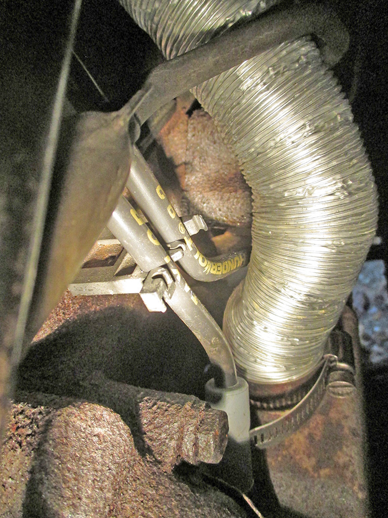
PARTS STORE TUBE
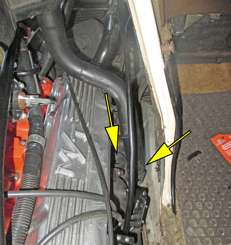
OEM STEEL TUBE
Once again, fleece bay to the rescue. The ad stated "hot air tube for GM carburetor not sure what year - do your research before bidding." It looked long enough to provide me with enough material to modify if I needed to. I had no idea if the diameter was right or not. With a "buy it now" of $1.99 (and six bucks shipping) I jumped in with both feet. I was stunned to find that not only was the diameter a perfect fit (at least to the air cleaner), but that the general shape was real close to what I needed. I will need to remove a section so the pipe will not be sitting on the rocker arm cover like it is at the moment. In the end though it's a damn good start.
I needed to remove a section of the tubing, which would allow me to raise it up off the rocker arm cover it was sitting on. I didn't want to take out too much like a whole inch, but if I took out too thin a slice how would I ever weld it back in at another section of the tube without melting it into oblivion with the heat generated by striking an arc with my welder?
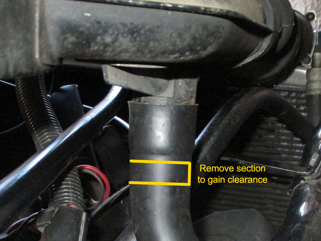
STEP ONE
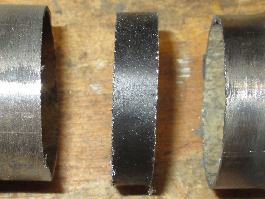
SECTIONED
After significant deliberation, I decided that I would remove 3/16th from the hot air tube. I could have taken out less, but as stated above this is going to be a compromise. Besides... I'm working with basic tools like a hacksaw, I couldn't cut things too precisely anyway, so this is how I began. Note to self: this is another instance where a nice little band saw would come in real handy.
Slicing the tubing up was child's play. Now what I have to do is set up the welder for the thickness of the steel I'm going to be working with. I took a vernier caliper to measure the thickness of a clean section of the tubing and came up with was 1.0mm or 20 gauge steel according to the chart on the inside of the door of my welder. Then I match the thickness of the steel with the wire I'm using (0.23) and the shielding gas (75% Argon & 25% C02) to get the recommended setting. This turned out to be a wire speed of 1 and voltage of D.5 as a starting point.
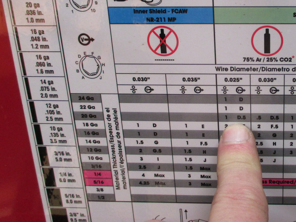
STARTING POINT
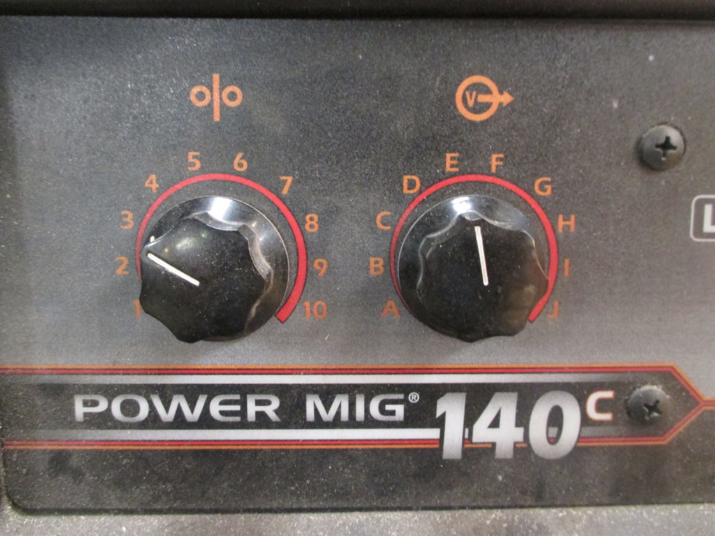
ADJUSTED SETTING
I say starting point because the first weld sputtered and laid on top of the steel. That meant poor penetration, so I upped the voltage to the letter E and tried that. More sputtering. I increased the wire speed to 3. I got a nice hot bacon sizzle sound and the weld sunk into the steel. This was one case where I couldn't practice on a section of the tube, because I need every inch. I ground down the high welds that were no good and began from the start.
Before picking up the welding torch, I cleaned the steel inside and out with sandpaper. Eventually I'll clean out what looks like dried mud from the inside of the entire tube. Right now I'm learning to be as consistant as possible as I move alone. Snip the wire to the same length each time, hold the torch at the same 45* from the work and pull the trigger for the same amount of time. Every time.
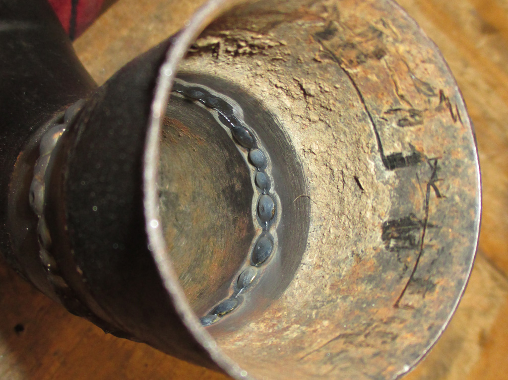
PENETRATION
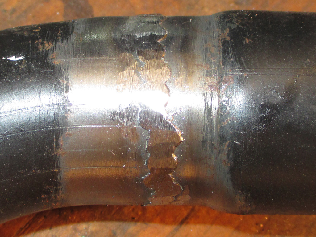
FIRST GRINDING
I have also begun grinding down the welds before piling on more and more wire. I eventually got into a rhythm of sorts, weld a little, grind a little, rotate the work in the vice and re-clamp. The angle grinder comes first, then I switch to the die grinder with an 80 grit 2" disk. Finally I finish off with a 120 grit. Once everything meets my demanding standards, I'll paint up all the parts.
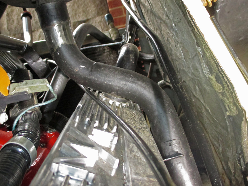
Here's the first test fit. I got the clearance I needed and then some. But this is only the first cut. As I go along I'll measure what needs to be moved and how, then continue to cut and weld until the job's done.
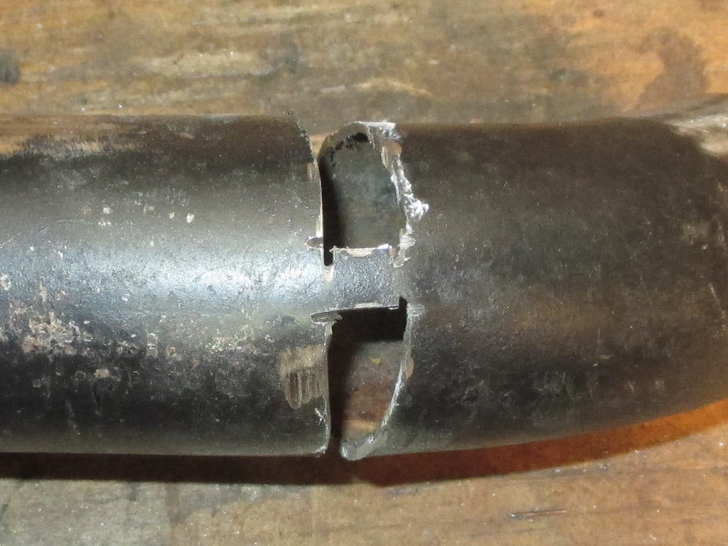
With the tube now clearing the rocker arm cover, it was time to align it with the connector on the exhaust manifold. It was pretty close, but close only counts in horseshoes and hand-grenades. I needed to move it closer to the block and forward at the same time. No pressure at all. I did this by looking at which way I needed the tube to move, marking where I needed to remove a pie shaped section with chalk and breaking out the hacksaw. The looking/studying part of the operation took the longest.
Now, remember those little pie-shaped sections of steel you just removed? You now get to trim them until they fit the opening that's left in the tube and weld them into place. I made a few tack welds, tapped the narrow end with a hammer so it was flush and continued welding. Remember, these slivers of steel are sharp, you don't want to end up bleeding all over your vice and down the leg of your pants. Most unprofessional!
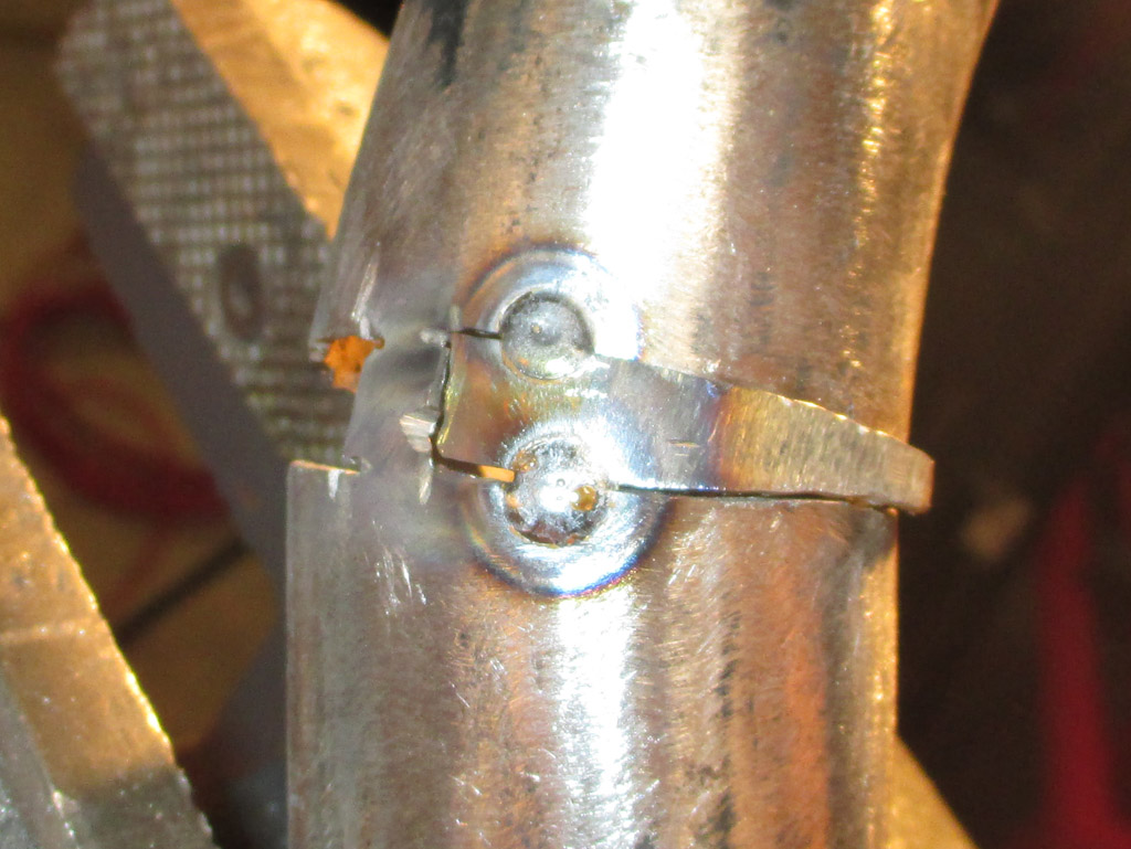
STARTING POINT
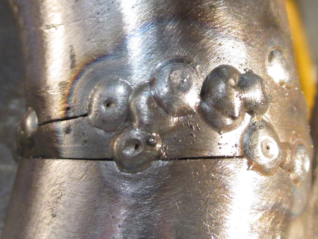
PROGRESS
This was the point where I finally adopted the weld a little, grind a little method of fabricating. By doing this, I don't just pile up weld on top of weld, I am able to get right down into a section I've missed and get the penetration the same as my previous tacks. I still haven't quite mastered the skill of stacking my welds in a nice straight line, but this project is a learning experience as well as modifying the tube to meet my needs.
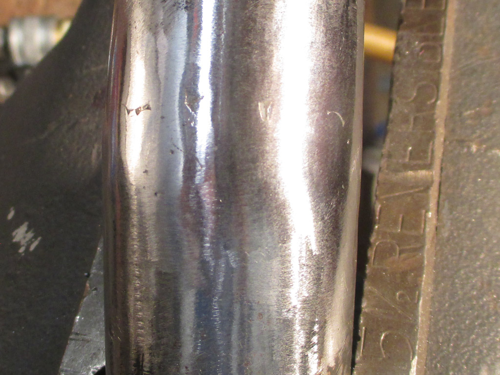
At this point I'm just about done with this area of the tube. I used the 50 grit grinding stone, then an 80 grit sanding disk to get to this point. I still have one last pass to make with either a 120 grit disk or a 180 grit, whichever I have in my supply cabinet. At that point it will be ready for paint. But I still have some more sectioning to do before I can call this done, so it's back to the railroad.
Now it was time to make use of the 3/16th slice I removed from the under-the-air cleaner section of the tubing. I now needed more height from the exhaust manifold fitting upward. I knew going in that I'd need every inch of the tubing I had, so I saved every little scrap from my hack job.
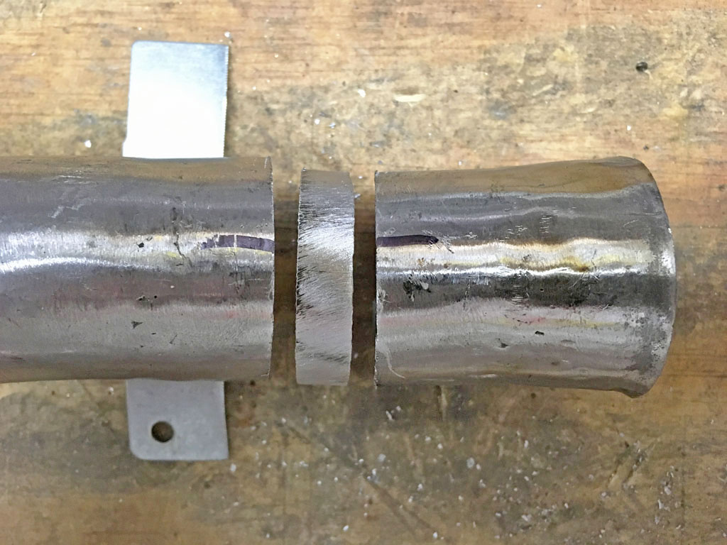
SECTION NEEDED
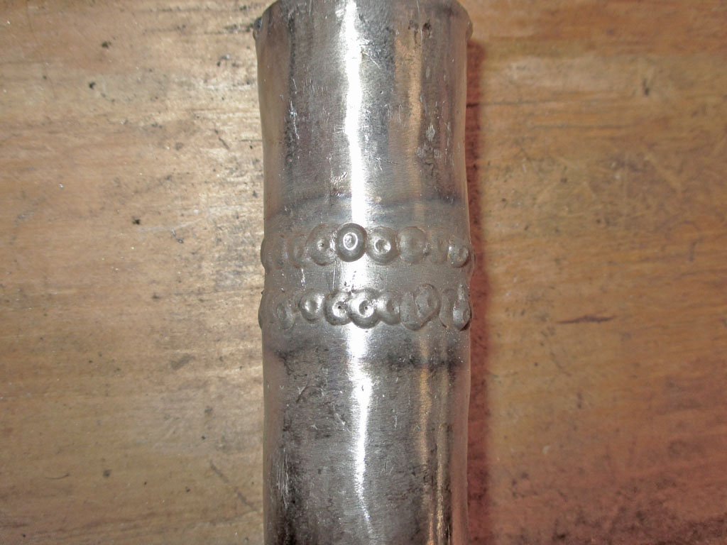
SECTION ADDED
Got a little better with my welding too. Still not quite overlapping each tack the way I want, but that'll come with practice. By the time I reach the end of this little project, I should have plenty of practice under my belt.
Once I had the vertical section separated from the horizontal, I realized something. The diameter of the tubing that goes over the exhaust manifold connection was just small enough to not fit. Naturally. That meant enlarging the diameter of the tubing, which I accomplished by slicing the bottom open, adding some steel and welding everything up again.
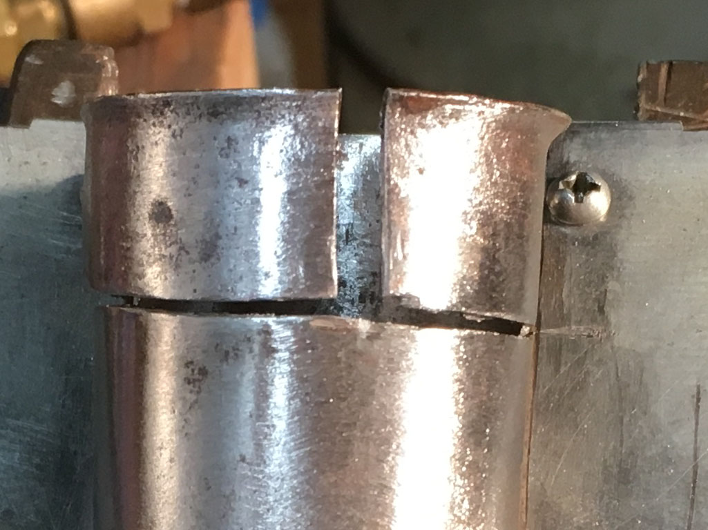
Expanded
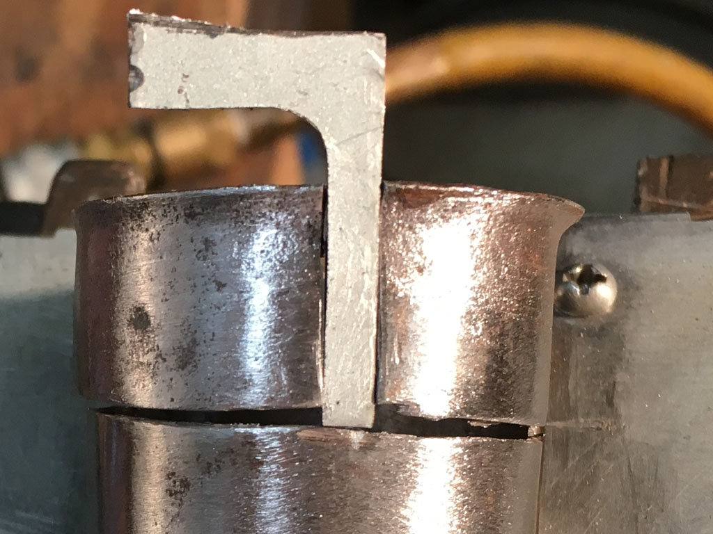
Added Steel
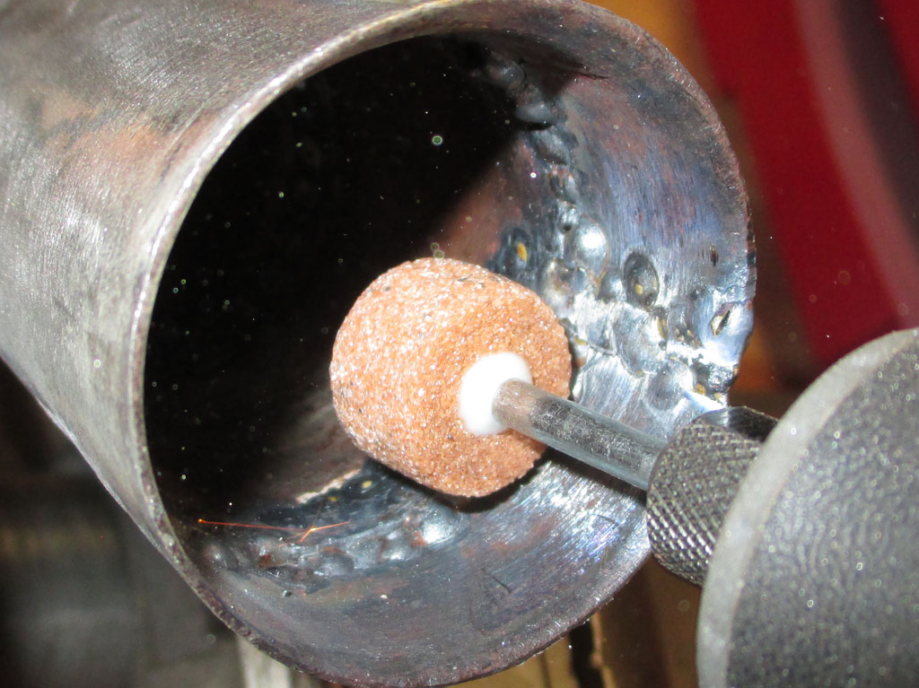
Grinding
I got good penetration of my welds... which meant I needed to grind down the welds on the inside for a proper fit. I broke out my Dremel equipped with a small cylindrical stone and went to work. It took some time to finish this, but I now have a hot air stove that fits the exhaust fitting as well as the air cleaner fitting. All I have to do now is get them to meet in the middle.
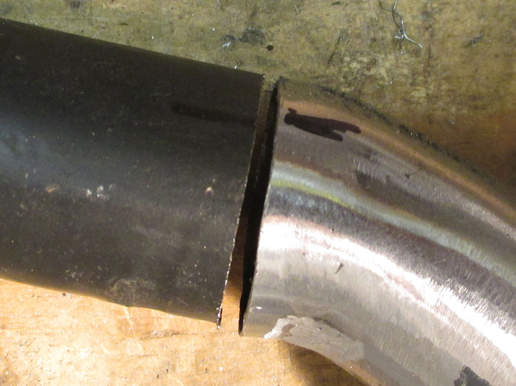
Once I got the vertical section properly fitted, I had to plan my next move. I marked the horizontal section (from the air cleaner) as I now needed to aim the tube rearward in order to meet the vertical section. I selected the spot, cut the tubing, rotated the 45* curved section and made preparations to weld everything back together once more.
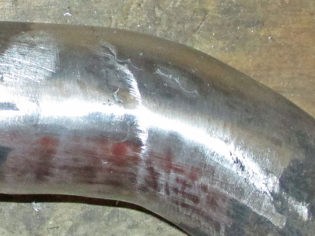
"Re-aiming" the curved section rearward was a piece of cake. The daunting part of the task came as I attempted to weld everything back together again. The area I was working on had been bent in a tubing bender. My theory is the bending must've thinned the steel and I was blowing holes in it left and right. I overcame this by establishing a tack to a thick enough part of the tubing steel, then tacking onto the previous tack until I had a solid surface again.
Of course the perfectionist ground off too much of the welding wire and I ended up with pin holes in the steel. Christ! Finally I decided to build up the whole area by about 1/8 inch with tack welds. I went nuts. Then I only ground off enough to get the shape of the bend right and called it done. In my relentless pursuit of perfectionism, have I unwittingly just invented "cosmetic" welding? Sounds simple enough, but it took a lot of time to pull off. Once I paint the whole thing satin black you'll never see it. I hope. Now I just have to connect both sections of tubing and I'll be done.
I've been trying to sort out a wire loom system for my plug wires for some time now. No matter which aftermarket style I experimented with, nothing was doing the job to my satisfaction. In fact, my purchase of this steel tubing was partially motivated by what I saw as a solution to the plug wire situation. I spent a chunk-o-change on these wires and I need to make certain they stay out of harms way.
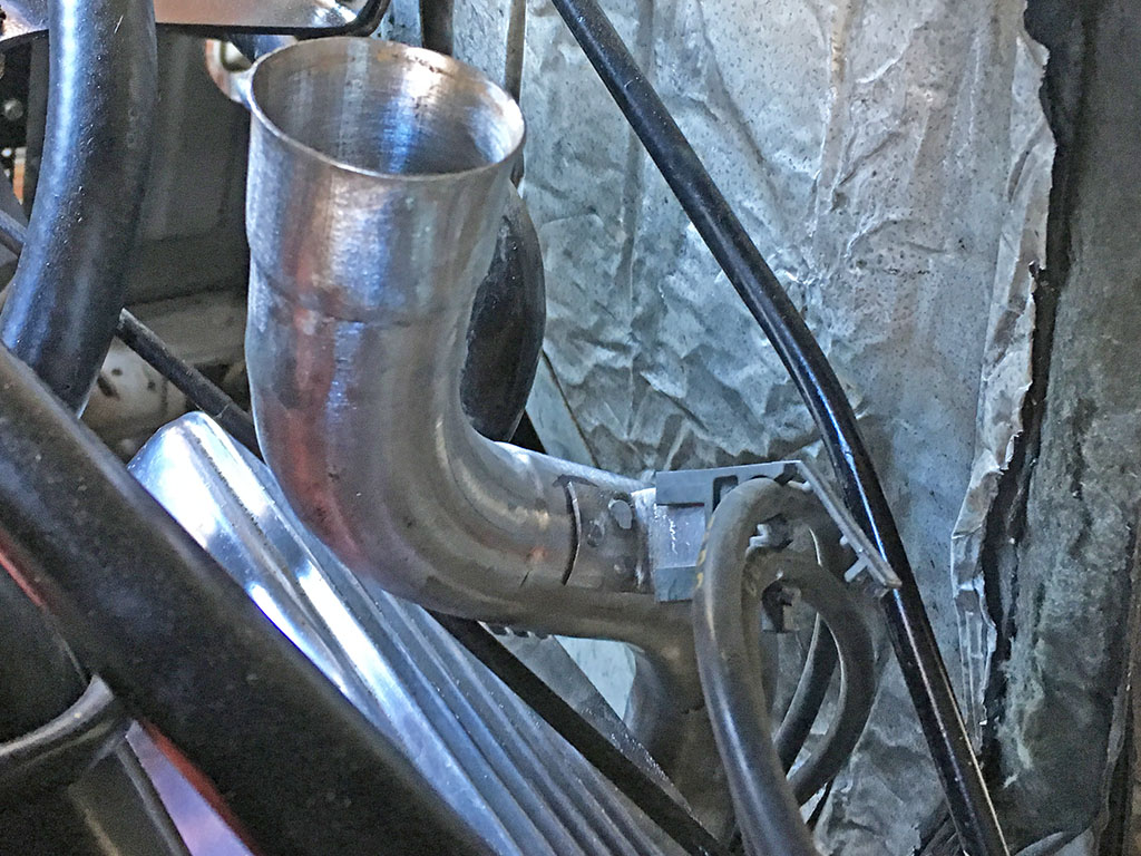
FINAL MOCKUP
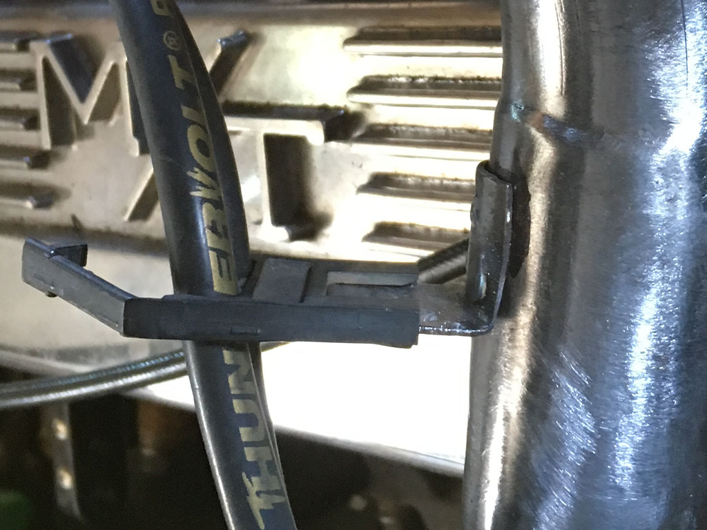
OEM WIRE LOOM
When I bought the tube, the wire mount clip was on the bottom. I drilled out the spot welds, repositioned the clip and re-welded it where it would do me the most good. Kind of interesting that the OEM style loom turned out to be just what was needed to solve my plug wire dilemma.
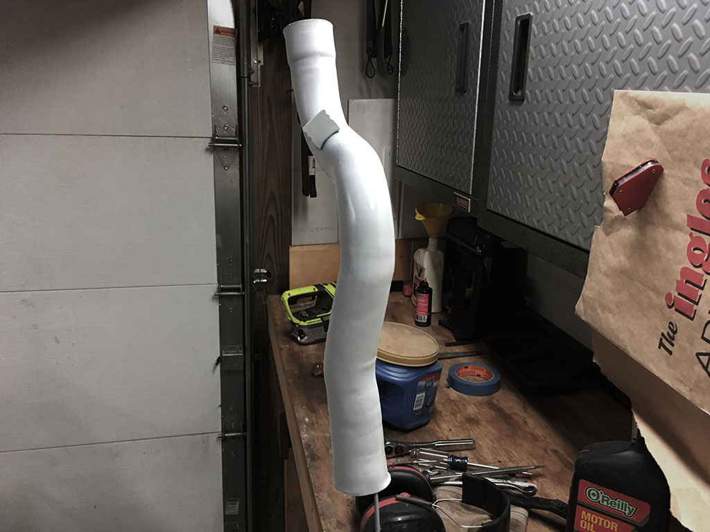
Here we are in primer. Finally! I used a small 180 grit "flapper" wheel to clean the inside inch or two of each end of the tube. I made sure to get primer (two light coats, one medium per instructions) shot inside both ends as best as I could. This project will solve two issues at the same time. I will now have a durable and long-lasting heat stove tube for the winter months and have a clean wiring system for my primary ignition wires. Win-win.
Brass
I drove my van around locally for about 6 months before discovering this little treasure. When I discovered it, the broken top nipple had been wrapped with black electrical tape... several years prior judging from the brittleness of the tape. I rooted around in my used auto parts array and found a straight vacuum port. But to clear the air cleaner you needed to make a sharp bend just shy of kinking the hose. Now, I was determined to replace the oem unit with a new 90* fitting. That was my goal.
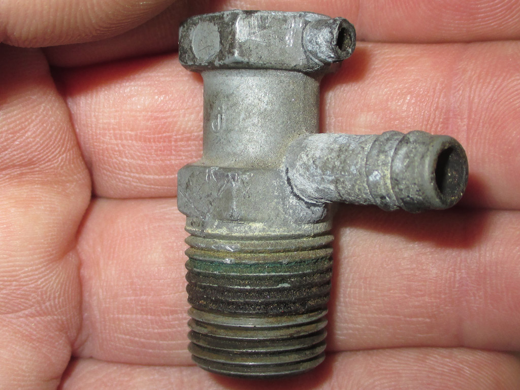
OEM VACUUM PORT
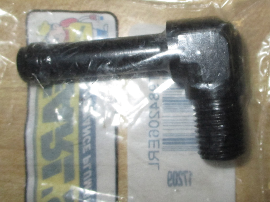
SUMMIT 2ND TRY
Back when I lived in Jersey, I'd run into New Brunswick and visit "California Speed & Sport" speed shop. For the street or strip, no matter what you needed they either had it, or could get it. Now I have to rely on Summit Racing mail order supply to get what I need. Without being able to talk to someone and show them the part I need, it's become trial and error. The second fitting was so ridiculously big... I mean what the hell am I supposed to do with this? Never mind.
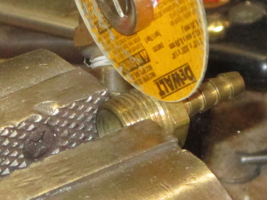
This really irked me. I went to several local auto stores, but no one had anything close. One suggestion was floated that I should check a wrecking yard. The only problem with that is anything from the mid 90's and up has already been sent to the crusher. Good luck finding something from the mid 80's with a fitting I could use.
Now I was pissed. I broke out all the brass fittings I had, determined to cobble together what I needed. I did this by starting with a male threaded adapter with a hose barb. I dug up a 90* fitting that threaded into the intake with a compression fitting on the other end. All I had to do was find a way to mate the two pieces. I got busy and sliced the threaded section off with a cut off wheel.
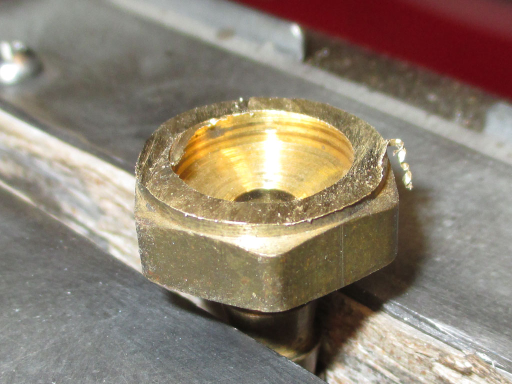
That brought me to this point. I used a Dremel with a cut off wheel to remove brass to roughly half the thickness of the hex head part of the fitting. In order to make this as flat as possible (and having no lathe handy), I had to get creative. I grabbed my portable drill and chucked the hose barb section into the drill. Instant lathe. I held the spinning brass against a sanding block until I had the thickness I needed.
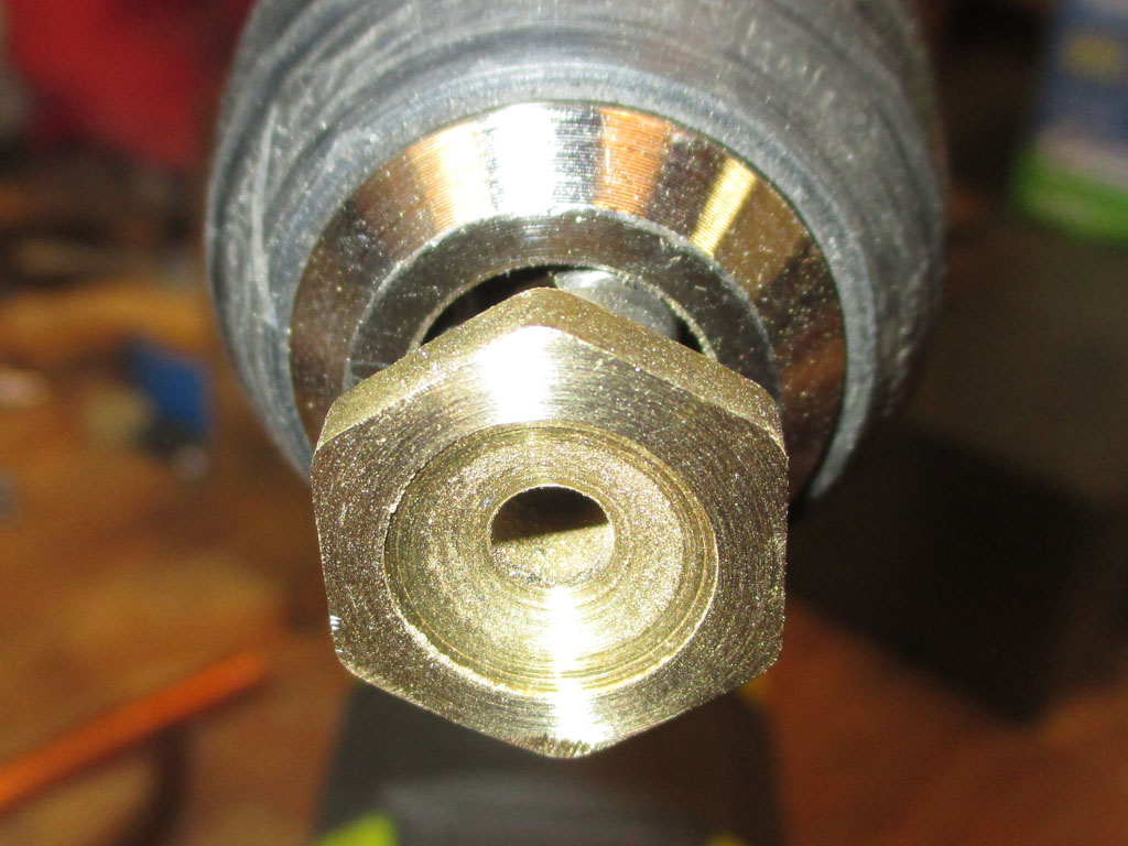
Thought I was kidding? Nope. Necessity is the Mother of invention and I was in mad inventor mode. The only issue remaining was how to round off the hex head section and make it small enough to suit its new role. I needed something perfectly circular to fit inside the compression fitting.
With the fitting chucked into my "Mr. Lathe" I fired up my bench grinder, set my drill to the highest speed and began carefully removing material. Sounds easy, but took forever due to all the test fitting and then more grinding. By having both tools spinning at the same time I was able to remove material evenly in a perfectly circular shape. Just the way I needed it.
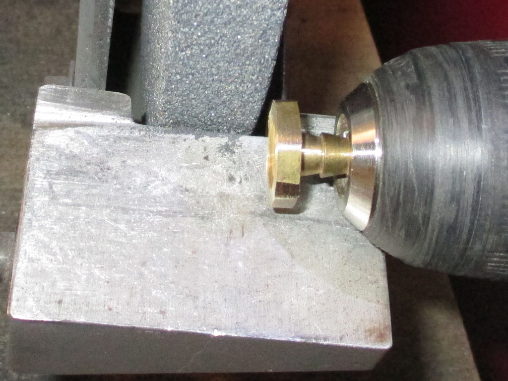
STEP ONE
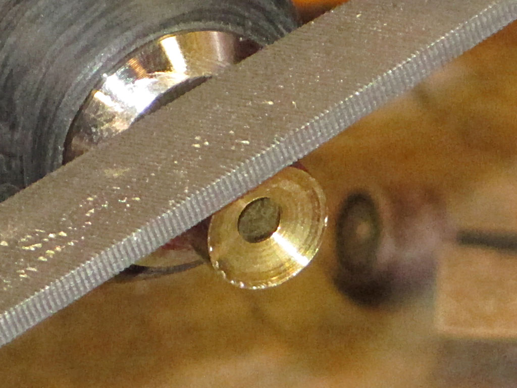
STEP TWO
Once I got pretty close to having the fitting sized properly for the ferule, I switched to "file power". I snuck up on things real slowly, filing a little, test fit, file a little more. The more test fits the less chance of going too far by mistake. In the end, I had just what I needed and since it's in two sections it should be easy to install on the intake even with the restricted space I have to work with.
So... I killed most of a day creating this little number. I've retained the same rust resistance as the original piece. Since I'm eliminating the vacuum switches that were fed by the smaller 5/16th fitting, the single hose barb is the right size I need for what's left. If I end up needing to connect to a smaller hose I can always use a plastic Y fitting to branch off a smaller size.
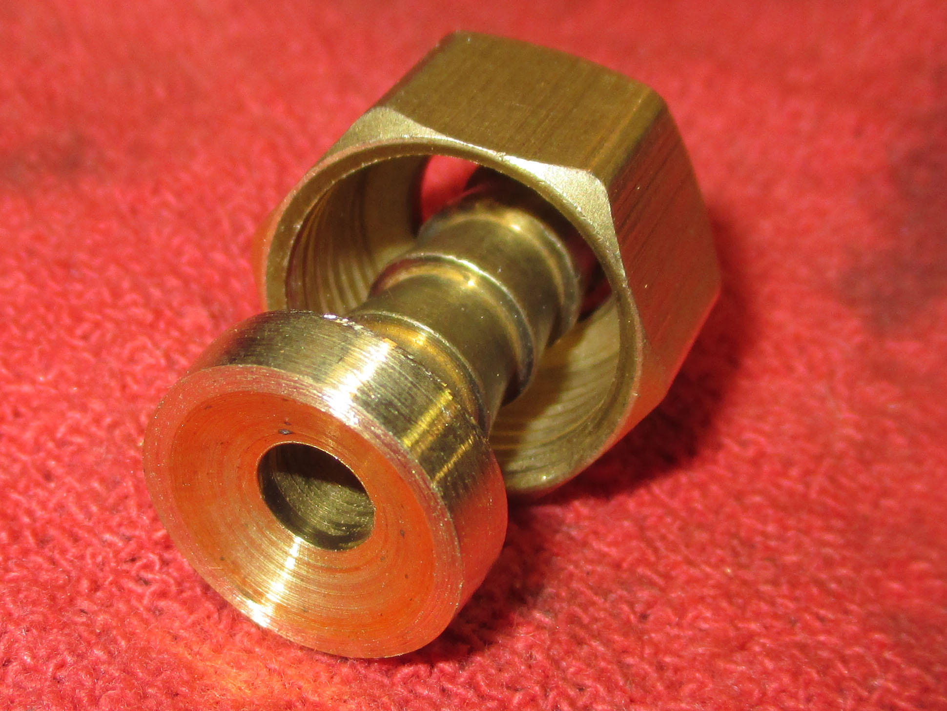
Machined
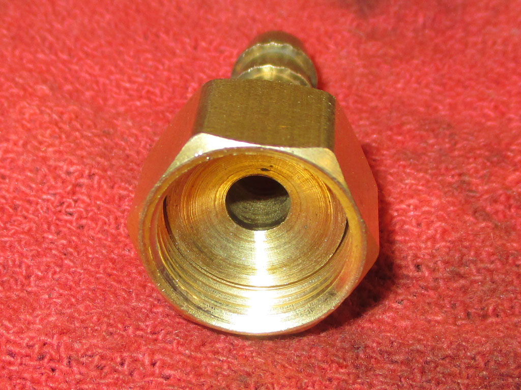
Tolerances
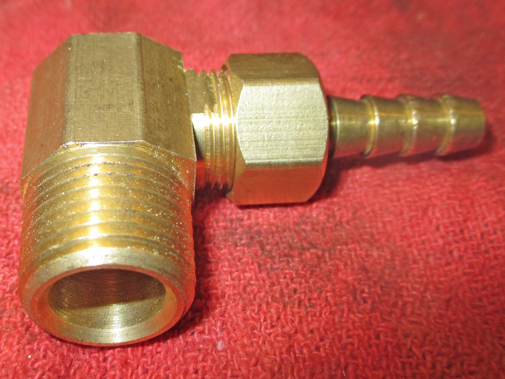
Ready
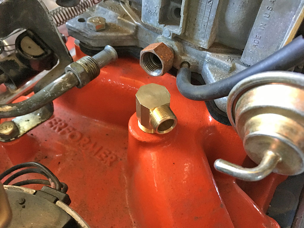
90* Fitting
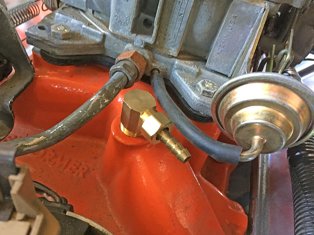
Hose Barb
This was an important step because it will now enable me to reroute several of the oem vacuum lines. Then any that are no longer being used will be capped off. Now I can move forward with reassembly.
Suspension
Rear Spring Replacement
June 2016
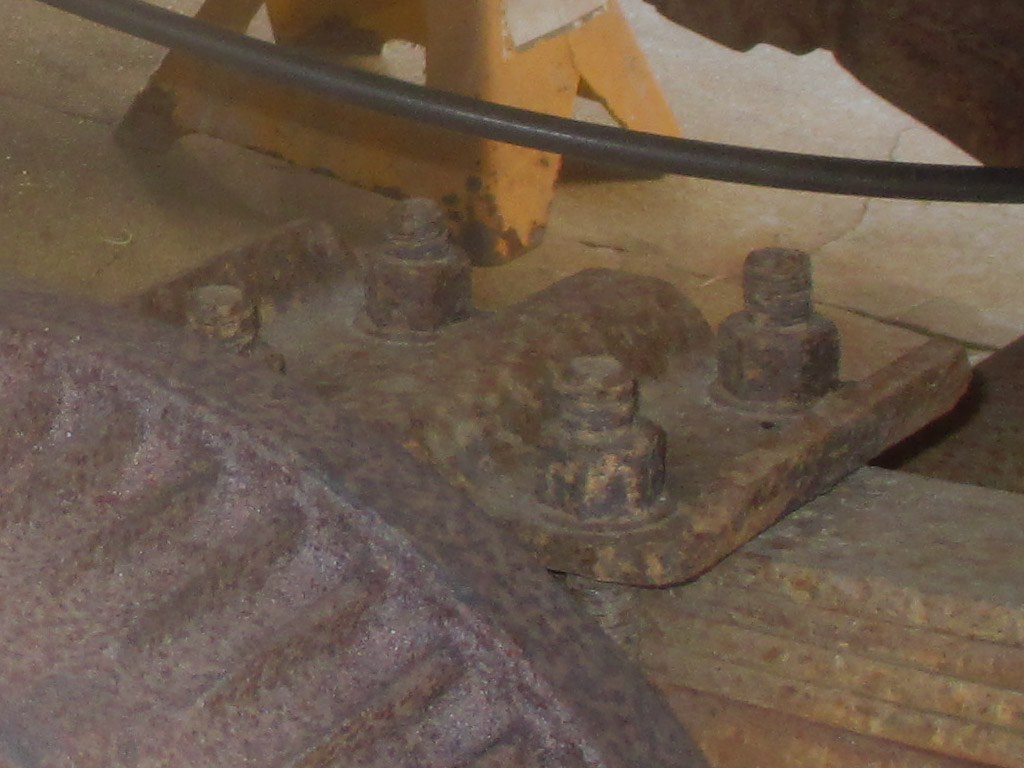
My generation of van is infamous for rear-end sag. To correct the problem, I checked out several options including re-arching the original springs. The price for this job was pretty reasonable, but they said there was no guarantee how long the fix would last and that re-arched springs are usually paired with a helper spring. When I discovered that little factoid, the idea of ordering a set of replacement leaf springs seemed like a better way to go.
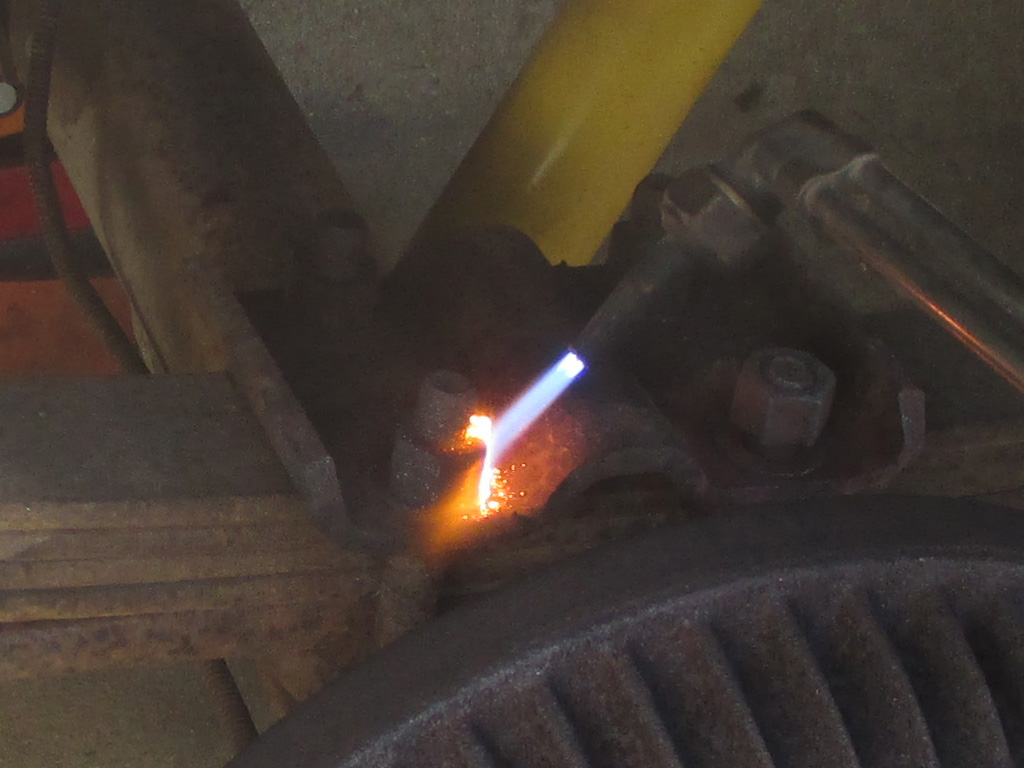
Naturally the first step in spring replacement is removal of what the factory installed. Since the factory completed said installation some 30 years ago, we were bound to run into some obstacles. Although technically a "Southern" van, I believe that it was used to travel on vacations to somewhere in the land of snow and salt. That meant we needed to enlist a bit of extra help in removing the OEM parts.
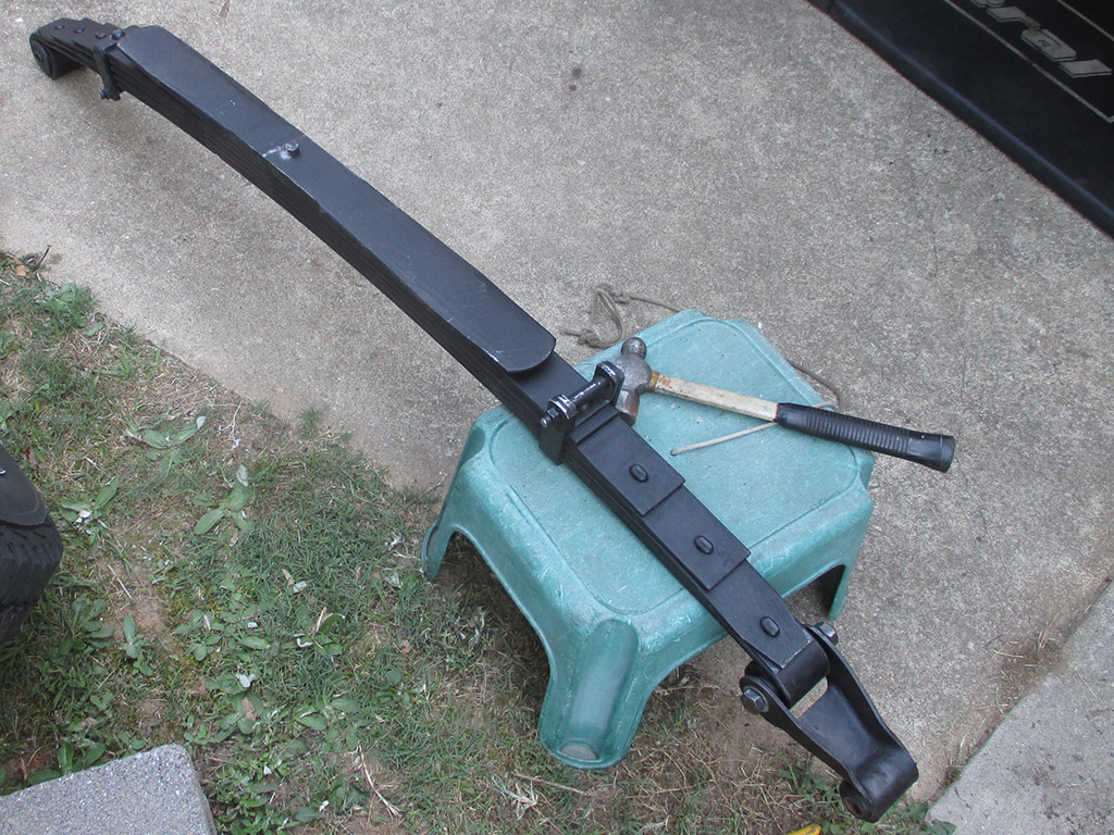
I went with General Spring Co.(located in Detroit) due to their use of US sourced materials and construction per their website. Much of what I've bought from Rock Auto is sourced from China or other non-USA sources. I ordered part #22-577 springs giving me an extra leaf on each side for a total of 6 leaves, listed for 1972 - 1991 GM G10/G1500/G20/G2500 vans and rated for 2100 lb. capacity each. The factory springs had 5 leaves (5 = 4 over 1 in spring talk). Just standing on the old springs compressed them visibly while the new springs didn't budge an inch.
At $149.99 each, the total came to $299.98 for the springs alone. The U-bolts were $8.00 bucks apiece, adding another 32 smackers to the pile of cash on the counter. And let's not forget shipping. There's always shipping, which in this case came in at $89.91 leaving me with a savings account lightened to the tune of $421.89! That being said, I found their prices fair and their quality excellent. I didn't have to spread or bend the U-bolts to get them to fit, everything simply dropped right into place.
While I did order new springs, U-Bolts and hardware, there were some things that I did need to recycle. The U-Bolt plates as well as the shackle bolts were all treated to a de-rusting party. I try my best to balance frugality with common sense. There's little sense in buying new parts when all the old ones need is a good cleaning and a couple coats of paint to be serviceable once more.
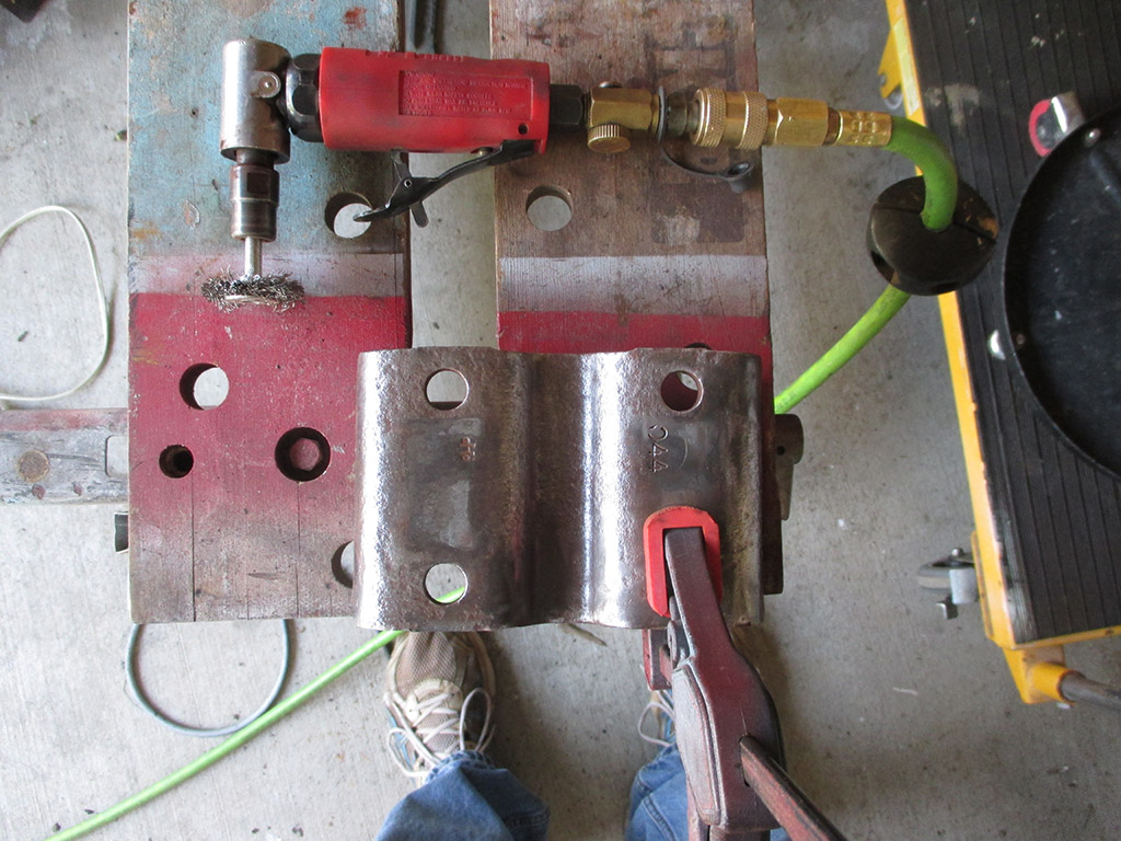
BOLT PLATES
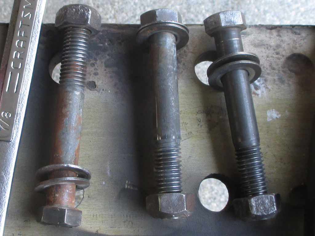
SHACKLE BOLTS
We installed both sides in one day, (including this little "parts beautification" session) even finishing them off with a couple coats of Zero Rust black. Okay, so maybe it didn't make everything beautiful per se, but in the constant battle against rust, it pays to be vigilant.
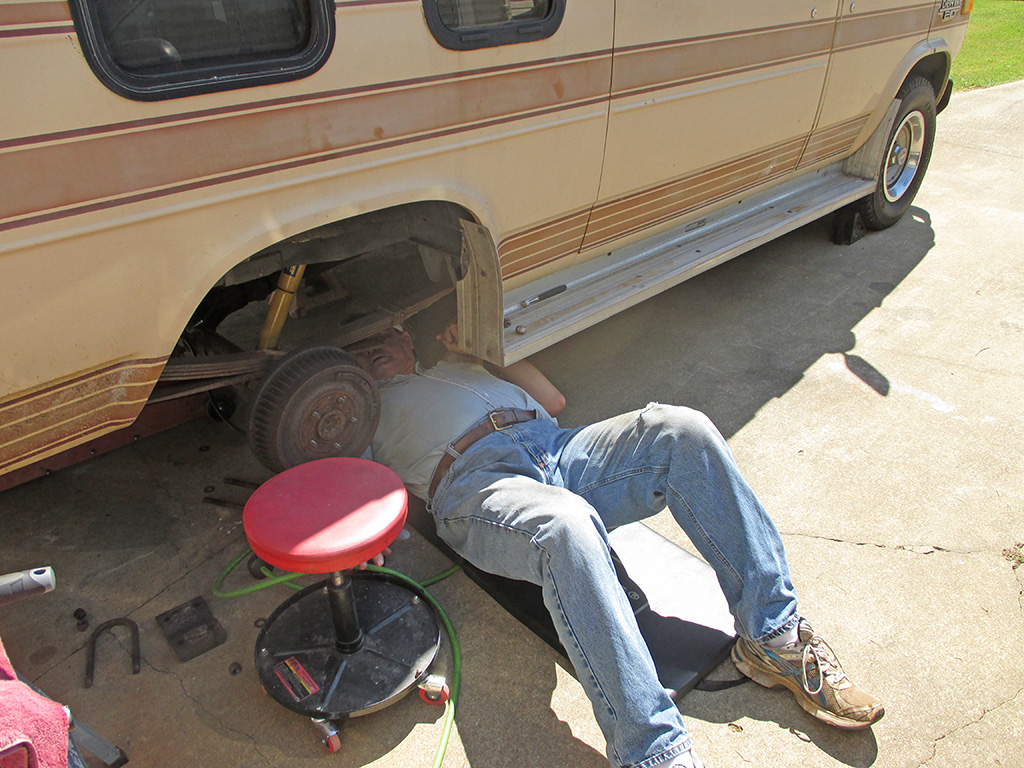
One side done, one to go. Here I'm test fitting the best way to install the springs. You have to slide the spring in from the front, lifting the front of the spring to allow the rear mount to slide under the rear shackle mount, then lift and pull the front of the spring into position. We discovered (through trial and error), that we had to mount the rear shackle to the spring, then lift it into place because done the other way around (installing the shackle in the van, then lifting the sprint into position) meant we didn't have enough room to slide the shackle bolt in.
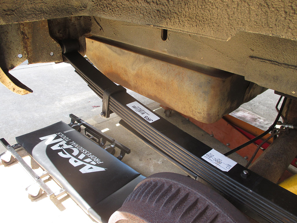
Nothing like standing out like a sore thumb now is there? Of course the goal of this little operation was function over form, but it still looks a little weird to see new semi-gloss springs contrasting with the rest of the underside of the van. One lofty goal for the future, is to equip the back axle with a posi-traction unit and then blast and paint the whole rear end. Let's see how long it takes me to bring that little dream to fruition.
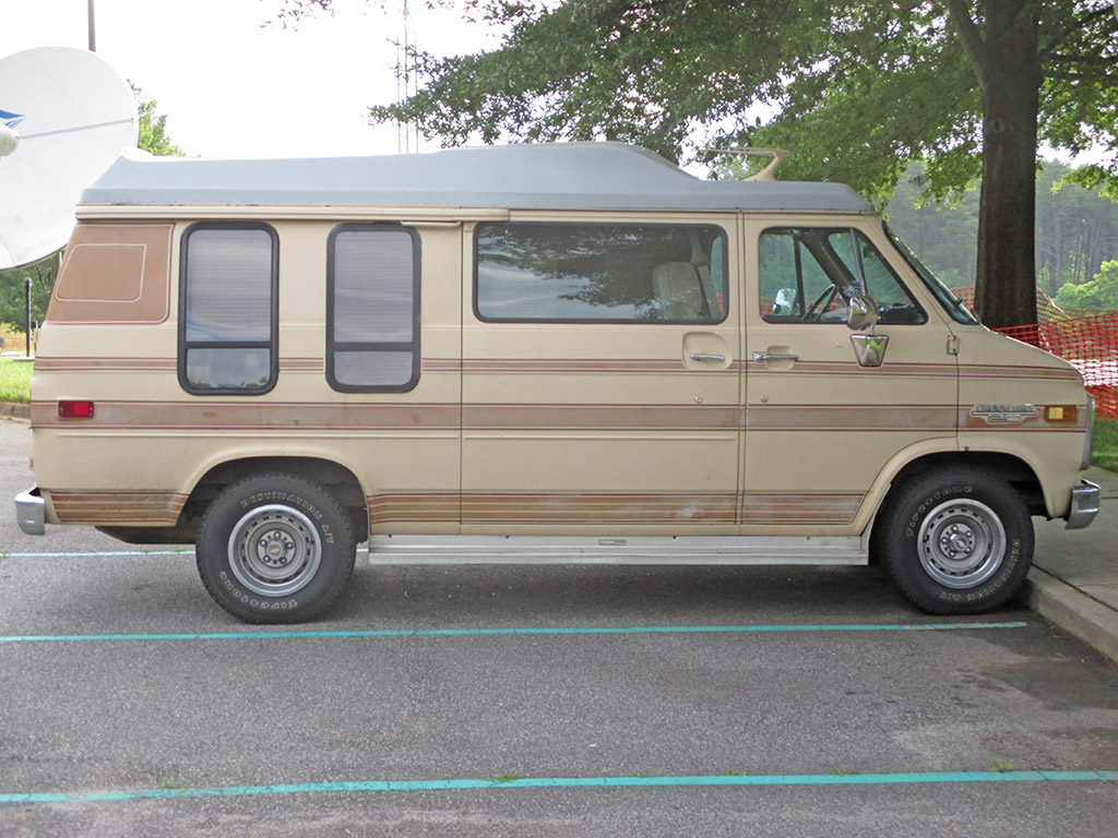
I took this shot parked in my usual spot at work. Before the spring replacement project, the top of the tire was just about even with the upper lip of the wheel opening. My van rides a bit stiff now with just me aboard and has a slight rake compared to the factory springs. My hope is that it will sit level when loaded and (in conjunction with the new shocks), provide a nice ride. I have already noticed an improvement in braking - the back brakes no longer lock up on sudden stops when some fool cuts me off. It also handles railroad crossings and other imperfect road obstacles with much more control. I'm calling this a successful upgrade to my van.
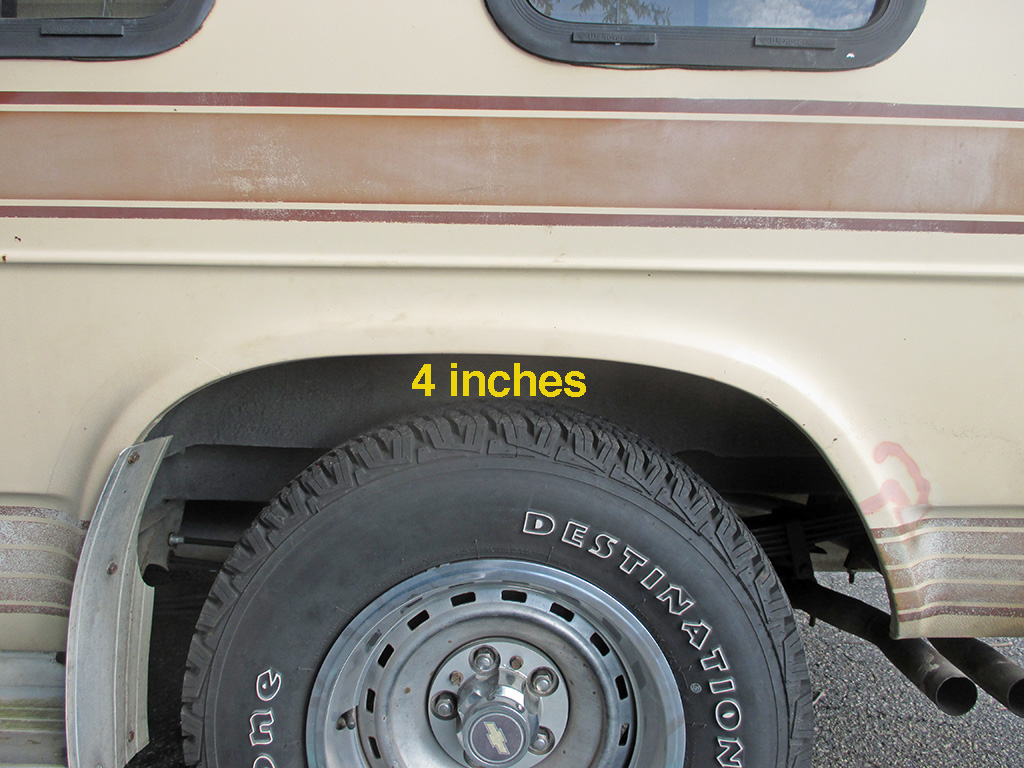
Curious about exactly how much this little operation changed the way the van now sits, I set a piece of angle iron on top of the tire, leveled it with a small level and measured the space between the top of the tire and the lip of the wheel opening. From what I can determine I lifted the back of the van about 4 inches empty. I haven't driven it fully loaded with either passengers or cargo yet, but now there is room for the springs to do their job without bottoming out all the time.
July 2014
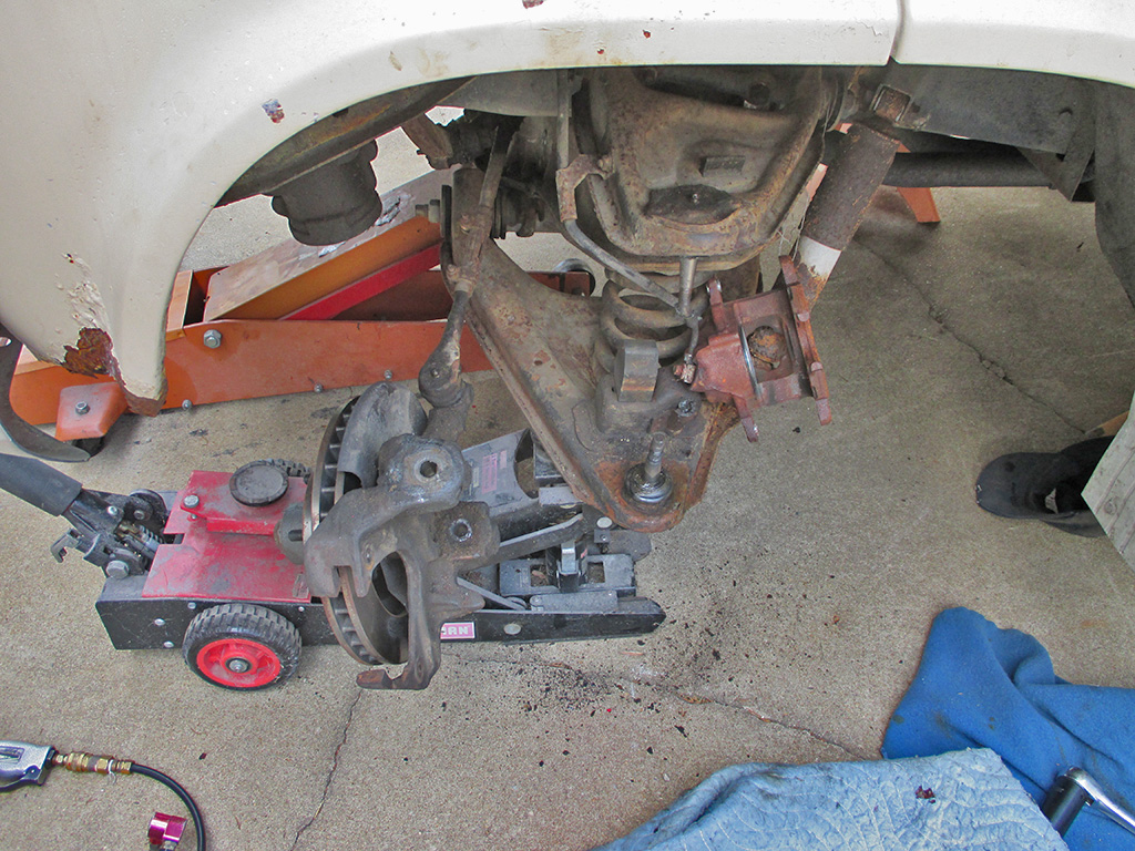
In an ongoing effort to make my van stop in a straight line (despite installing new calipers/pads & rotors), I plunged headlong into the intricacies of the front suspension. An in depth check of the front end turned up play in the lower ball joints. So... its off to the auto parts store for some fine offshore parts which will certainly fall apart within the first 100 miles bring my van back to factory specifications. I hope.
I broke out the shop stands, chocks and floor jack and got down to business. Here I've pulled the wheel, removed the cotter pins from the castle nuts and then loosened up those nuts leaving both in place temporarily for the next step. An air hammer equipped with a "pickle fork" attachment was used to free each ball joint stud from the spindle. It took time (I thought nothing was happening at first) and then BANG! the joint was separated. The nuts acted as stops to keep the spindle from coming all the way off until I was ready to do so.
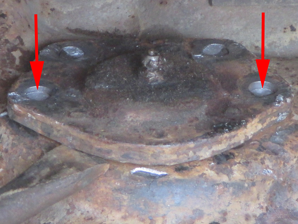
After using the rivet cutter to chop the tops off each rivet, we switched to a sharply beveled chisel to free the ball joint from each of the four rivets. After several minutes the two outer rivets (arrows) were already coming free. It took quite a few more minutes (moving back and forth working to free each rivet), before we could declare success as the joint came free. Not too bad... only one more like this to do on the other side, then it's on to the lower ball joints.
I broke out the shop stands, chocks and floor jack and got down to business. Here I've pulled the wheel, removed the cotter pins from the castle nuts and then loosened up those nuts but left both in place for the next step. An air hammer equipped with a "pickle fork" attachment was used to free each ball joint stud from the spindle. It took time (I thought nothing was happening at first) and then BANG! the joint was separated. The nuts acted as stops to keep the spindle from coming all the way off until I was ready to do so.
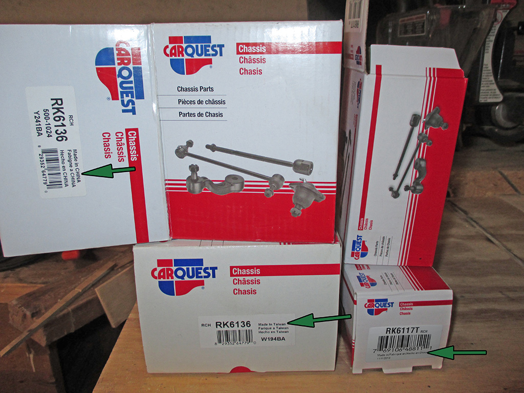
Once both uppers had been "persuaded" to come out of the upper control arms, it was getting to be time for lunch and a parts run. There was a time (not that long ago either), when there would have been no question. I would have gone to the local auto parts store, purchased some Moog suspension parts and gotten on with the job at hand. Upon completion, there was a sense of satisfaction that the job had been done properly with the highest quality parts available for a long lasting repair.
Currently a one-income household, I have to be careful how I spend what little remains of my car hobby budget. This meant making some tough choices. The clerk at the parts store says no one's had a problem with them (that they know of), the price is about 1/3 of the big name brand and perhaps most important of all... these are in stock when your van is sitting high and dry on a pair of jack stands. Anything else will have to be ordered. That means at least a one-day delay in the project. So I bought these, leaving me feeling a little like I'd turned my back on a crime I could have done something to stop.
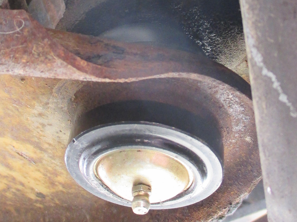
No action shots of the process I'm afraid (sometimes when you're in the zone, you don't think about degreasing your grubby paws, getting the camera, then getting back to work again) but here is the finished replacement sitting in its new home. We used a typical balljoint press (think C clamp on steroids) and some of the included adapters to press the old balljoints out of each lower control arm. Then we used the same tool with different adapters to press the new joint back into place.
Installation was definitely more difficult as the new balljoint kept wanting to cock and get pressed in crooked. This required re-positioning the clamp to put pressure on whichever side had the largest gap between the balljoint seat and the lower control arm hole. Crank on the installation tool, hit it with a hammer a couple of times... repeat as necessary. Then it was time to torque the nuts onto the balljoints and install new cotter pins.
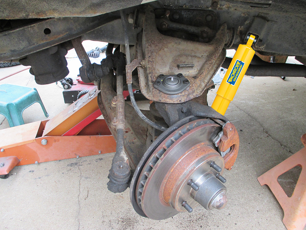
Even with an uncooperative weather pattern raining down all over my project, my task was accomplished. New upper and lower ball joints on each side, hoping after all this work they last awhile since they were "affordable" and in stock. These days there's no guarantee traditional name brands are manufactured in the US anymore. I went with Monroe Gas Magnum shocks, since they have a thicker piston than others I'd browsed on the net, and this is one heavy vehicle. The box said made in USA, but then you wonder... are they referring to the box or the contents?
Some manufacturers (no doubt in response to foreign-sourced consumer complaints), have resorted to the rather cryptic "Assembled in USA using USA and/or globally sourced parts" basically corporate-speak for "we outsourced our parts too, but want you to think they're still made here." Rather than throw my hard earned cash away such a gamble, I tossed my principles out the window, purchased Car Quest parts and got on with the job. It was raining pretty good by the time I got to the shocks, but I got both fronts installed regardless.
So... after all this the van still pulled to the left upon application of the brakes. Having read of the same exact issue with another Chevy G20 van on Vanning.com, I went out and purchased some Raybestos (made in China again!) flexible front brake line hoses in an attempt to rid the van of its left-leaning tendencies. My father-in-law thought it was air in the lines, since I already had the hoses on hand... we did both. After another round of bleeding the air from the new lines, we went on an extended road test to check our work.
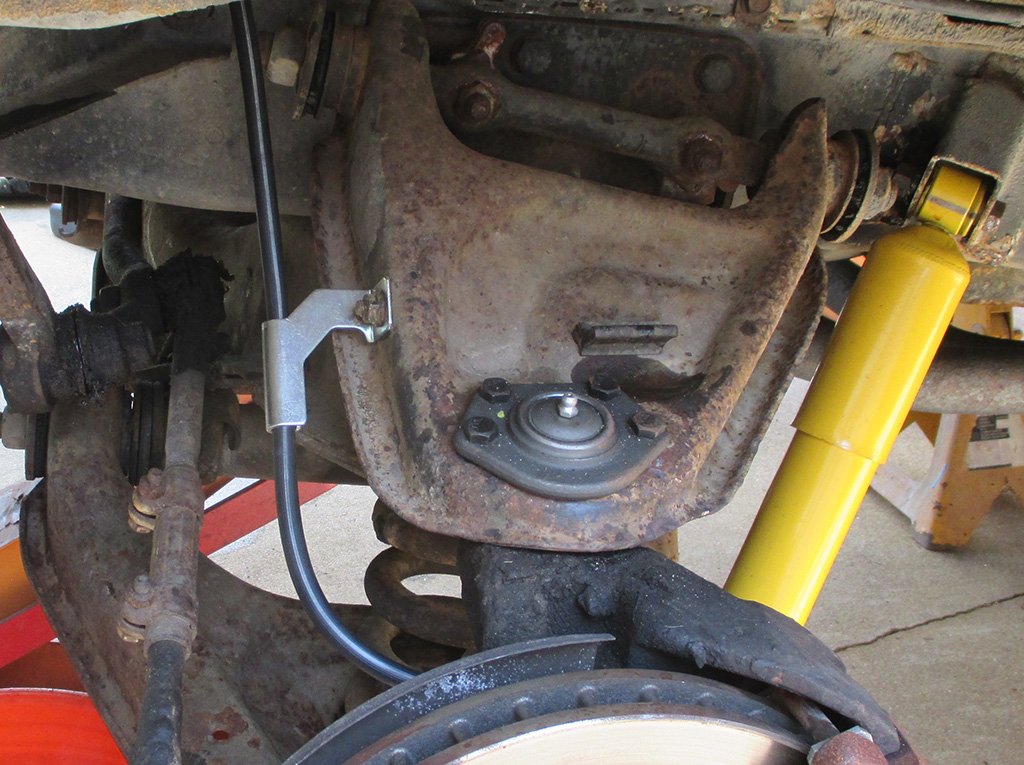
DRIVER'S SIDE
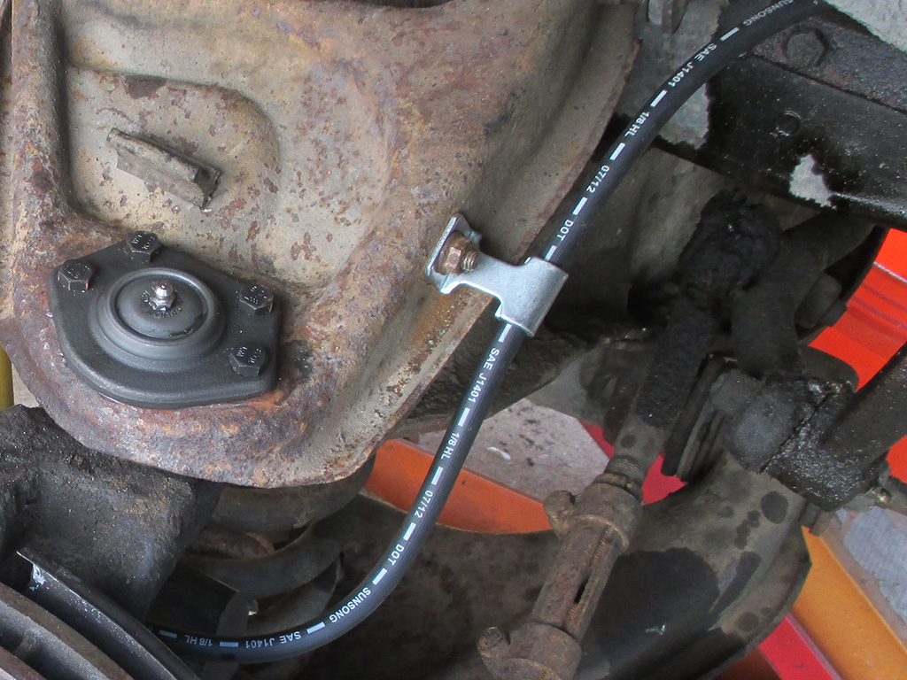
PASSENGER SIDE
Amazingly, the damned thing stopped in a straight line! Even when I simulated a panic stop, locking up one rear wheel. The hell! Once back in the driveway I was hesitant to declare success, but the problem does seem to be solved at this point I should hope so, after all the new parts I threw at this thing. The van still stopped straight on our drive home later that evening. So I guess I can actually drive the damned thing safely now. It'll take some time for me to be thoroughly convinced, but things are definitely looking up. We also got the rear shocks installed during this session.
Dem's Da Brakes
October 2013
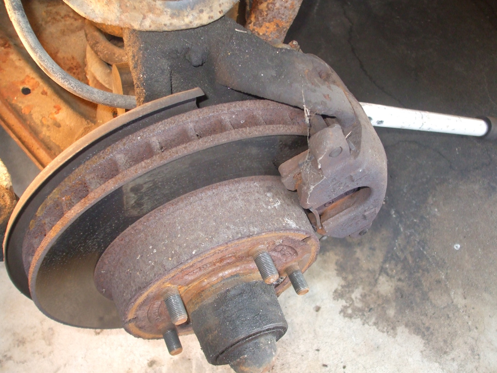
Ever since the day I drove my van home, there has been an issue with the brakes. Attempting to stop in anything other than the most leisurely fashion requires some wild steering corrections due to what feels like a sticking caliper. On our way back from GSVR there's a long downhill grade on the interstate... this introduced the first instances of vibration through the steering wheel and pulsing in the brake pedal. Clearly there's something amiss here, and a beautiful October day was the perfect venue to dig into things and ascertain just what the hell's going on down there.
Step one, remove front wheel. Step two, remove brake caliper. Step two required the addition of a leverage bar to break loose the mounting bolts of the caliper. The rotor itself was not deeply grooved, nor was it hard to turn (indicative of a frozen caliper), but my mission to solve my brake woes includes machining both rotors, installation of new pads, hoses and (still on the fence on this decision) possibly remanufactured calipers as well. As with all projects, ya gotta start somewhere and that meant breaking out my trusty impact wrench. The driver's side lug nuts were reasonably tight... the passenger side took quite a bit of "machine-gunning" to break free.
The inboard pad on the driver's side did not look bad at all, still having quite a bit of meat left on it at this point. I didn't know whether or not to expect razor thin pads, or metal on metal, or who knows what. I wasn't expecting to see something as normal looking as this. Same story with the outboard pad, still lots of life left there as well. Hmmm, now what?
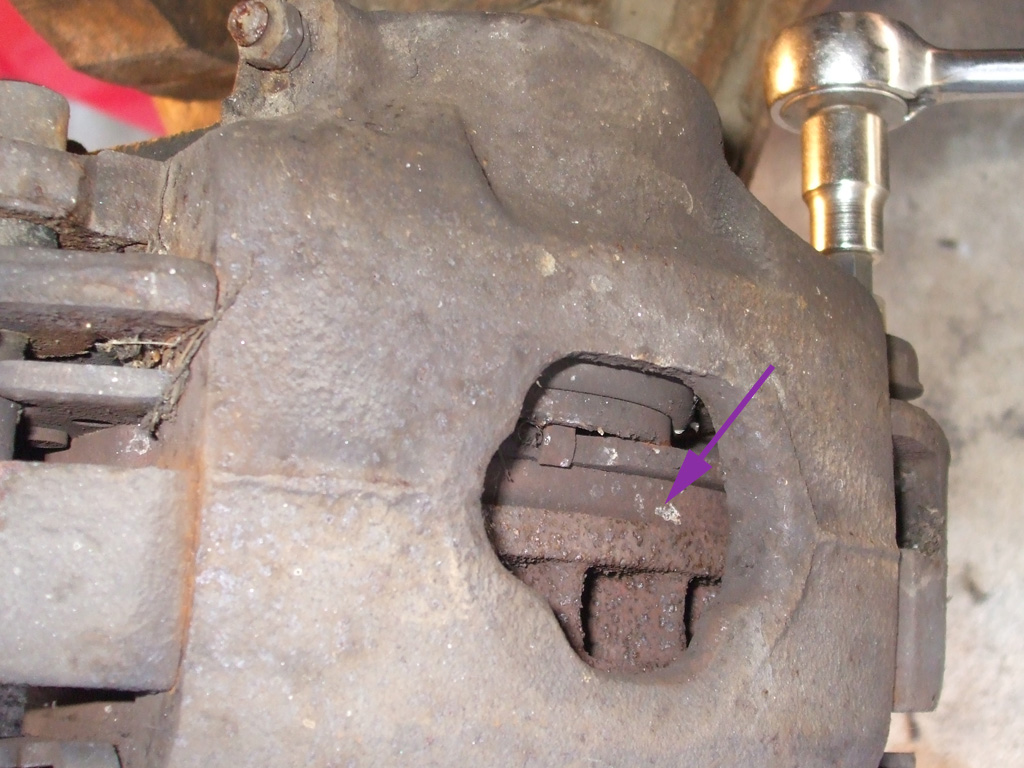
INBOARD PAD
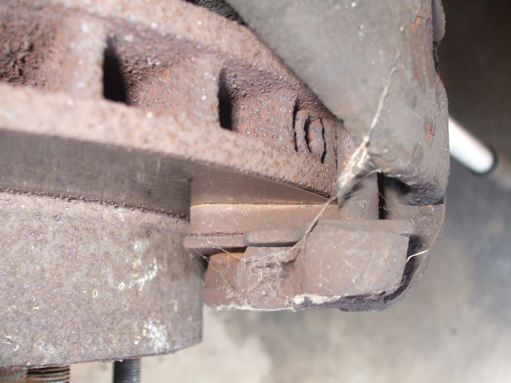
OUTBOARD PAD
In for a penny, in for a pound... I removed the caliper, wired it up out of the way and then removed the pads. The brake hoses are a different story. They're probably original to the van (at least they look that way) and having read the experiences of other Chevy van owners on the interwebs, I'll definitely be replacing both front brake hoses while I'm under here. And that means... bleeding the brakes! What fun. Now in the past, I have had caliper bleeding nuts work fine with no problems whatsoever, while others have snapped off requiring a new caliper.
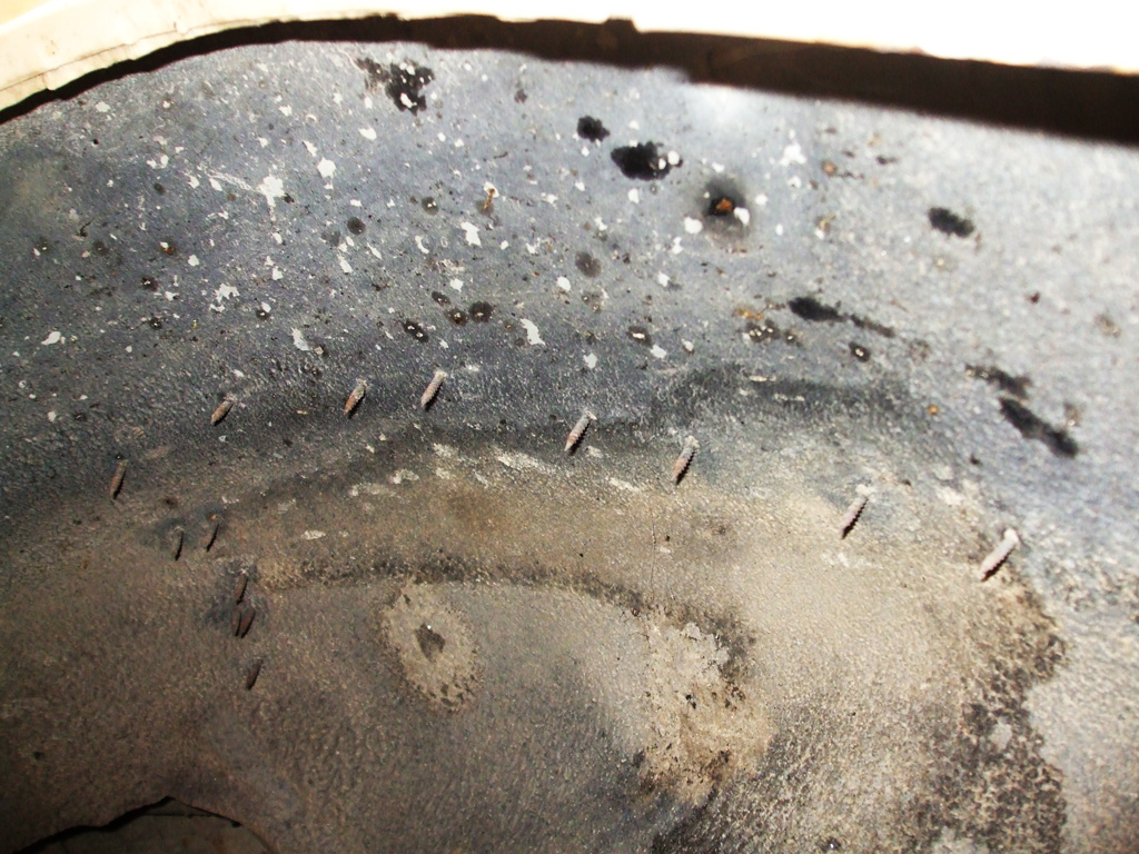
With the caliper wired up out of the way I removed the dust cover, cotter pin and castellated nut and popped the rotor off. I moved over to the passenger side, set up my drop light and discovered these. A whole row of screws (from inside the van) aiming straight down at my new (expensive) tires. Are you freaking kidding me?!
Before proceeding with the job at hand (it was still early afternoon) I immediately took a detour to find out the purpose of these screws and remove them. It didn't take me long to determine that the screws had been used to mount the carpet to the floor since the factory trim piece (evident on the driver's side) was non-existant. Nice solution bung-holes!
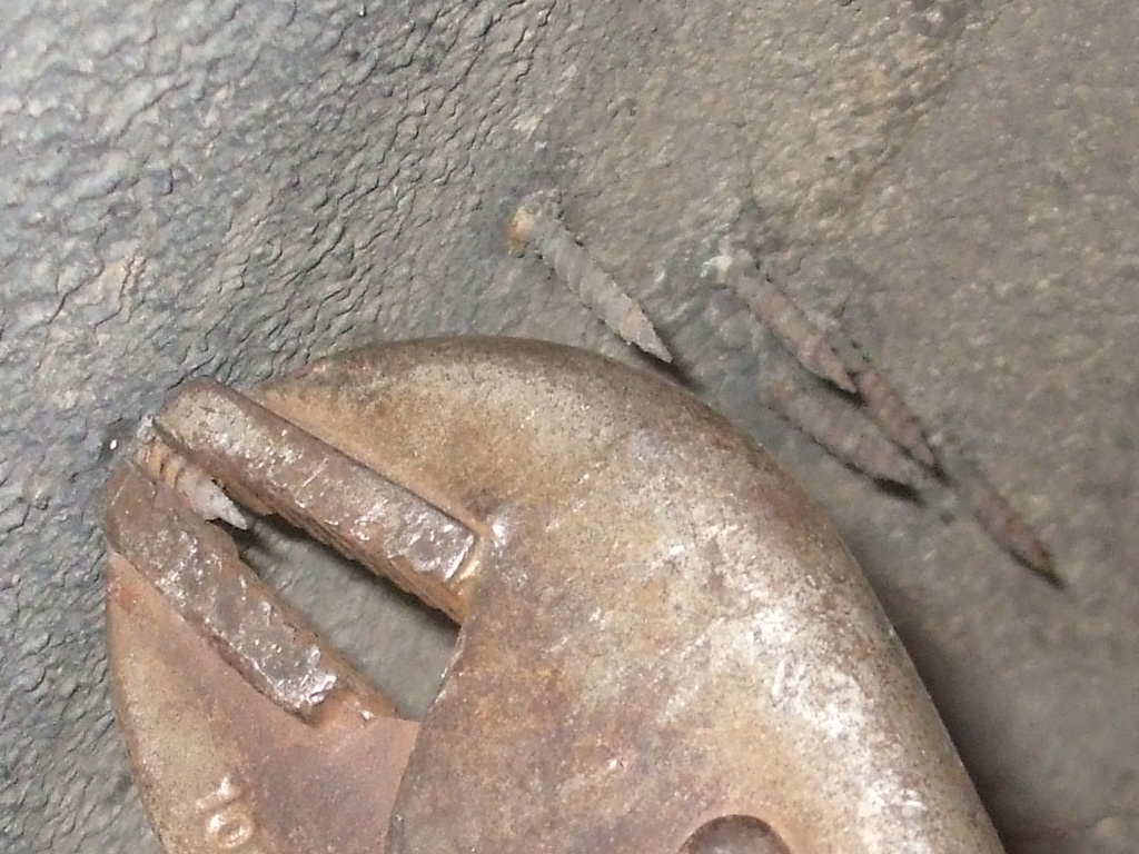
With no screw heads visible from the inside (no doubt buried in the cut-pile carpeting), I needed to find a way to expose them. The solution was simple enough. Since I could see the business ends of the screws, I grabbed a pair of Vice Grip pliers, snapped them onto each screw and turned them back in until they were flush with the inner fender well. It may sound dumb, but it worked!
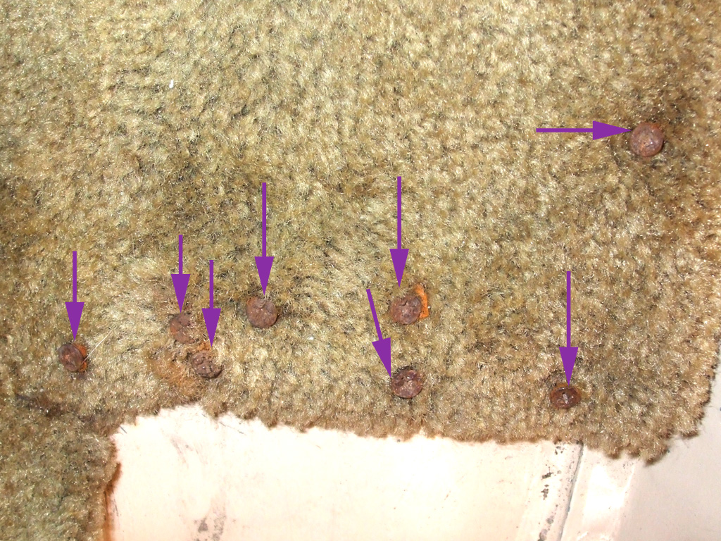
Passenger footwell carpeting. The purple arrows emphasize the eight (out of a total of fourteen!) sheetrock screws the conversion company used to mount the carpet to the passenger side footwell. They used adhesive too, but this was just... stupid. Thanks to these dumb asses I now have fourteen holes to weld up, paint (from inside) and re-undercoat (from the wheel side) because no one thought to buy or fabricate a piece of trim like they used on the drivers side.
When I pulled up the carpet to make sure I got all the screws, I could see discoloration (mold?) so the carpet will eventually get replaced. I'm not sure if there was a windshield leak (doubtful since the roof gutters show signs of leakage) or some other source of water that caused the mold. Either way I have to make the van water tight before I can consider carpet replacement. When I was through I did go back and disassemble the brake calipers, pads and rotor on the passenger side as well, only now I have another interior task to perform.
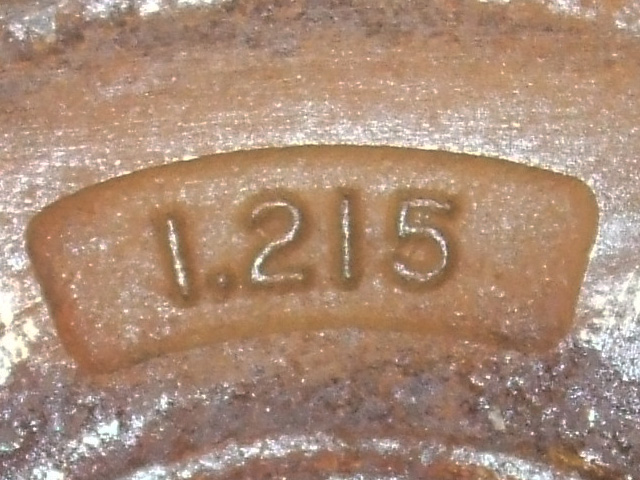
Meanwhile, back on the brake refurbishment front, I removed the bearings and grease seals from both front rotors in preparation for (hopefully) having them machined or turned so they would bed in the new brake pads properly. Unfortunately, this turned out to be a pipe dream on my part.
I figured with all the meat left on the front pads, everything would be relatively okay wear wise. The counter man at the auto parts place miced them and found both were beyond the minimum thickness required for machining. You know what that means... yep, time for new rotors.
Since there is NO WAY I'm putting off-shore sourced cheap-crap rotors on my van, I pursued other options. I decided to pony up for some Bosch rotors, which is at least a brand I've heard of (as opposed to "Brake Best" which sounds suspiciously foreign) and might even be from a country whose name I can at least pronounce.
Not cheap though. We're talking $60 Bucks apiece (including $9.00 shipping each), as opposed to $38 each for "Brake Best" rotors. So we're looking at $140.00 just for new (hopefully good quality) brake rotors. I'm not cheaping out on my brakes. No way!
Never one to blindly trust someone whose business it is to separate me from my money, I decided to check things out for myself. Since each rotor is stamped "MIN THK 1.215" checking them out with my own micrometer was pretty simple. One was definitely out of spec., while the other one was... close. But with liability issues being what they are nobody was going to machine these. Murphy strikes again.
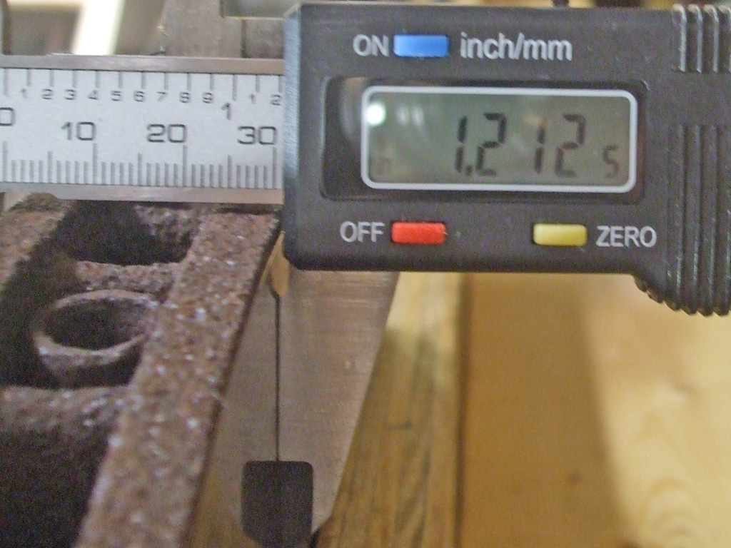
LEFT ROTOR
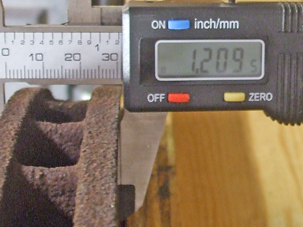
RIGHT ROTOR
The other parts aren't too bad cost wise. The calipers are the cheapest (even asking for high quality parts as is my norm) coming in at 13.99 each. A full set of Wagner ceramic front brake pads come in at right around $50 bucks. I haven't priced the flexible front brake hoses yet, but they're getting replaced as well What fun. But in the end if I end up with smooth safe brakes it will be worth it.

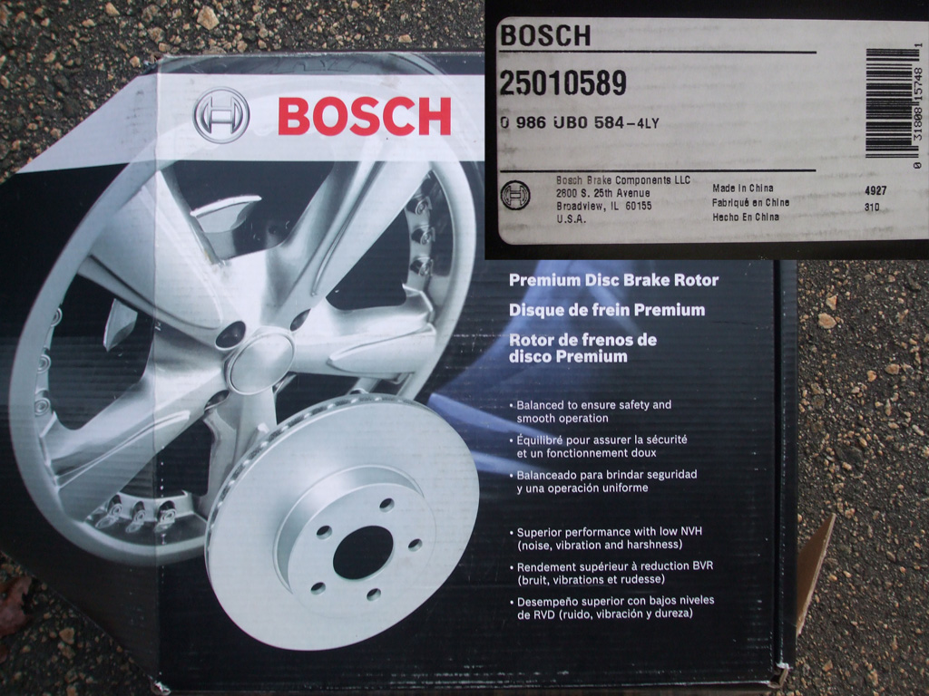
So... with all my determination to buy USA sourced parts... I end up with BOSCH rotors. Now, what would you associate the name BOSCH with? I'm pretty sure you'd think what I thought... a European or Germanic country of origin at least, perhaps even (dare I hope for), German made? Would you think of Japan? India? China?
Counting on the fact that I had to special order what were touted as premium rotors (one parts guy telling me he'd used them with excellent results), you can imagine my surprize upon lifting up the flap of this box, see inset. NOOOOOOOOO!!!!! So this friends and countrymen is what it's come down to when you attempt to purchase (special order, extra $$ shipping), quality parts from your local O'Reilly's. The two big "A" national chains were no better.
Originally, I'd wanted to replace the brake hoses as well... you know... just to be sure the entire front brake system was totally refurbished. So, I saddled up and made the rounds of the autoparts stores seeking QUALITY brake hoses. First up, the Local Mom & Pop independant (where I've bought Gates belts and hoses and WIX filters) thinking maybe...

Nope. The parts man trotted out a couple of (very dusty) boxes of Dorman brand parts made... yep, you know where. Funny thing was, parts man really didn't give a damn. Wished me good luck in finding USA sourced parts. Nice attitude butt hole.
I got a little more irked with each setback, convinced perseverance would win out in the end, ranting to myself at the outrageousness of the whole situation. Finally, it was time to stop in at my last resort... NAPA, (the only local store is 15 miles away), remembering in the past that their fanbelts were made by Gates. Some of the locals I've met waiting in line at the parts counter are of the opinion that NAPA thinks an awful lot of their parts and charges accordingly, but as the day dragged on I was running out of options.
I thought I hit paydirt with the Raybestos brand, but when the parts man checked where they were made (I'd wised up by this point in the procedings)... made in China! Arrrgggghhhh! Are you F-ING KIDDING ME? Later, dude. The nearly 30 year old (not made in China) hoses will have to suffice.
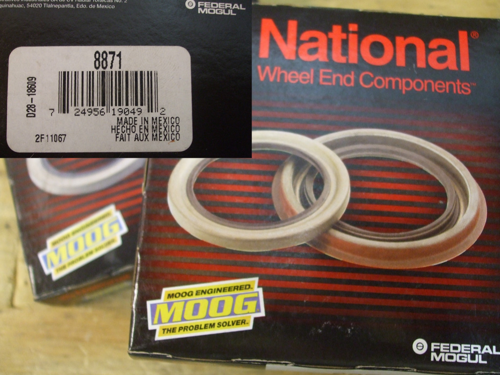
In the past (really need to get back to work on that time machine), I traditionally bought Moog suspension parts, Bendix or Wagner brakes, names you had grown to know and recognize as quality parts. Hell, I don't even know what the point is any more. Some global economy. Most stuff made in China. Mexico providing a cheap labor force. Guys like me? We're dinosaurs. Throw-backs that need to get with the program.
We've got no time for you and your petty Nationalism. China's all we got. You don't want it... move along, nothing for you here. You want quality? We got us some gen-you-ine Chinese quality right here man. All you need. Nope, not if I can help it.
Not wanting to play around with rebuild kits (showing my age again I know) I bought some remanufactured calipers. No country of origin stated or implied. Let's call them anonymous calipers then, they've got the GM logo (unlike the smooth Chinese ones I've seen), so at least there's some hope there.
REMANUFACTURED
FINALLY!
I guess the Chinamen haven't made inroads regarding brake pads as I was finally able to purchase items made in the USA. Evidently good ole' Wagner is still out there somewhere churning out what may well be the last bastion of quality left in North America. I'm speculating wildly of course. I have nothing to back up these claims, other than reports of unrest in China. Seems workers there are organizing wanting better salaries and working conditions. Sound familiar? Maybe the end of slave labor is finally in sight. Maybe that's what it'll take for jobs will return to the US someday.
Carburetor
January 2016
The worst thing you can do to a vehicle (or any machine really), is to let it sit. My van sat because I was working on fixing the roof, which had leaked when I purchased the van. Due to unforeseen circumstances (namely a bigger air compressor to spray the paint without constantly running), the project bogged down, and then winter settled in. So my van hibernated beneath my steel carport awaiting the finishing touches. My plan was to paint the roof this spring and get all my other projects back on track. Nope.
In early November, my daily driver 2001 Silverado called it quits with a dead transmission. Wonderful. Got it towed home, hopped in the van, backed it out of the carport, put it in drive, and there it sat... one wheel spinning in the gravel, the other locked up solid. Perfect. That problem (like I needed another problem) turned out to be a frozen rear brake cylinder. We eventually worked the rear drum free so the van got pulled into the garage for a rear brake job, the fronts having been previously rebuilt over the summer. I went nuts and fixed the frozen parking brake (replacing all the rusted cables) while I was at it.
The van would chug and rock at a stop light and if I saw an opening in traffic and "punched it" to merge, it would backfire through the carb and stall. Going down a level road at a constant speed, it would backfire, run rough for a while, then smooth out again. After trying high-test gas and all types of fuel treatments, I just ran several tanks of gas through the thing hoping it would improve. I tried a basic tune up (new plugs, wires, fuel/air filters, distributor cap and rotor), which produced zero improvement. So I bit the bullet and decided to rebuild the carburetor.

I did not make the decision lightly, having failed in a previous rebuild attempt years ago. Now I have little choice. The van is no where as reliable as I need it to be. A new carburetor would run me roughly $300 bucks I just don't happen to have laying around at the moment.
So I purchased some "Chemdip" locally - a highly corrosive, nasty parts cleaner (how often do you purchase a can of material sold inside a Ziplock bag?), a rebuild kit from the outfit shown here and a new float. I searched the 'net including hotrodders.com and several others and bought the two books recommended by several to help me understand the process. I watched hours of YouTube videos that showed how the job was done. I was as ready as I was ever going to be.
With the van promoted to daily driver status, any repair work I do has to be finished in time for me to go to work on Monday mornings. No pressure there. The aforementioned brake job was done on a Monday... I burned up an annual leave day because I had no other choice. I had some Christmas vacation time coming, so I got everything ready that I would need to tackle the job. I have no doubt in my skills, I just need enough uninterrupted time in which to accomplish this task. I gave it priority over a home improvement project I'd been planning, just to have reliable transportation once more. The unit I'll be working on was a staple of GM cars for over 30 years, the Rochester Quadrajet shown here.
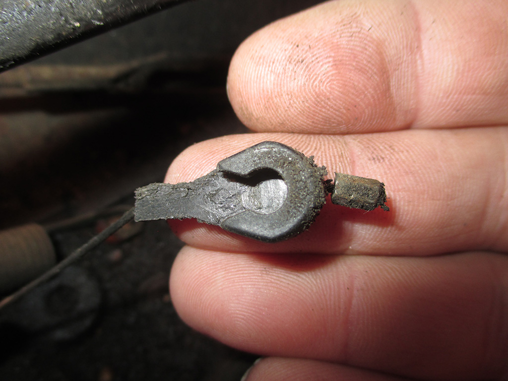
After removing all the necessary "stuff" (vacuum lines, AIR hoses etc.) from the passenger side of the unit, I turned my attention to the driver's side of the carb. And hit my first roadblock. I wasted quite a bit of time trying to figure this out. I've removed carbs like this before, but I just couldn't remember how I'd done it in the past.
I tried to gently pry it away from the carburetor body, but that wasn't it. Then I tried pushing it forward (opposite direction of the way it pulls) but that didn't work either. Finally I moved the throttle linkage until I could aim this straight down at the intake manifold and pushed down with my needle-nosed pliers. That worked and off she popped. Ridiculous!
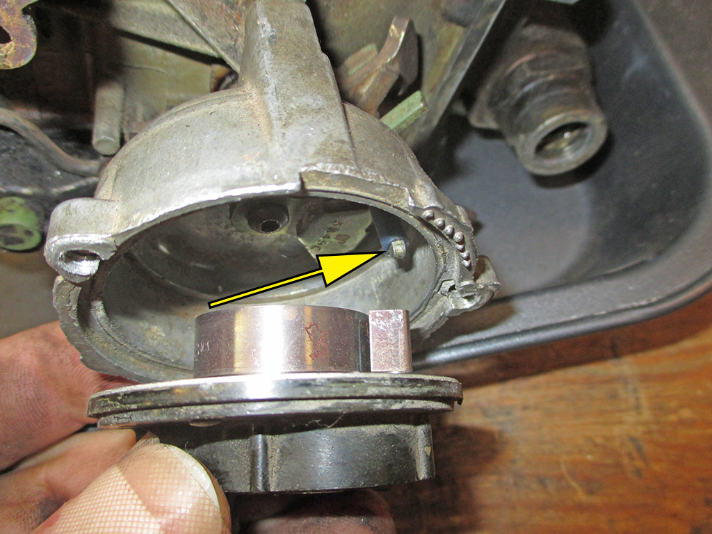
I recycle a lot of cookware in my humble little shop. If the non-stick coating is shot, I grab it out of the trash to use in cases like this. Fully expecting this thing to start pissing gas all over my workbench, I plopped it into an old baking tray trying to be neat about things. Problem number one... virtually no gas (maybe a tablespoonful), was all that leaked out. The gas had to go somewhere now didn't it? We'll come back to this a little bit later.
Knowing how complicated this can be, I charged up my digital camera to document the whole process so I would not forget where stuff went. Like the electric choke coil seen here. Will I remember where the bimetallic spring goes when reassembly comes around? Snap off a couple of shots and I'm good to go.
The choke pull off (proper nomenclature: vacuum brake), has two rods that perform two jobs simultaneously. Imagine the thought processes that must've gone into designing this little setup.
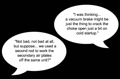
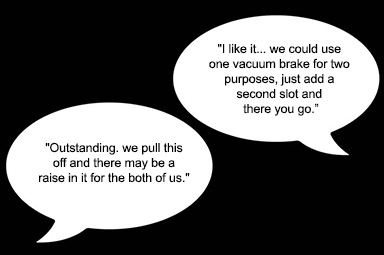
Replacement of the vacuum break can be done on the vehicle. You will need an extraordinary amount of patience to accomplish this task. Particularly when you need to bend the rod to adjust the degree the choke plate opens, remount the break, and check your measurements. Repeat as required. I was able to perform this delicate little operation about four times before the black rod fell off.
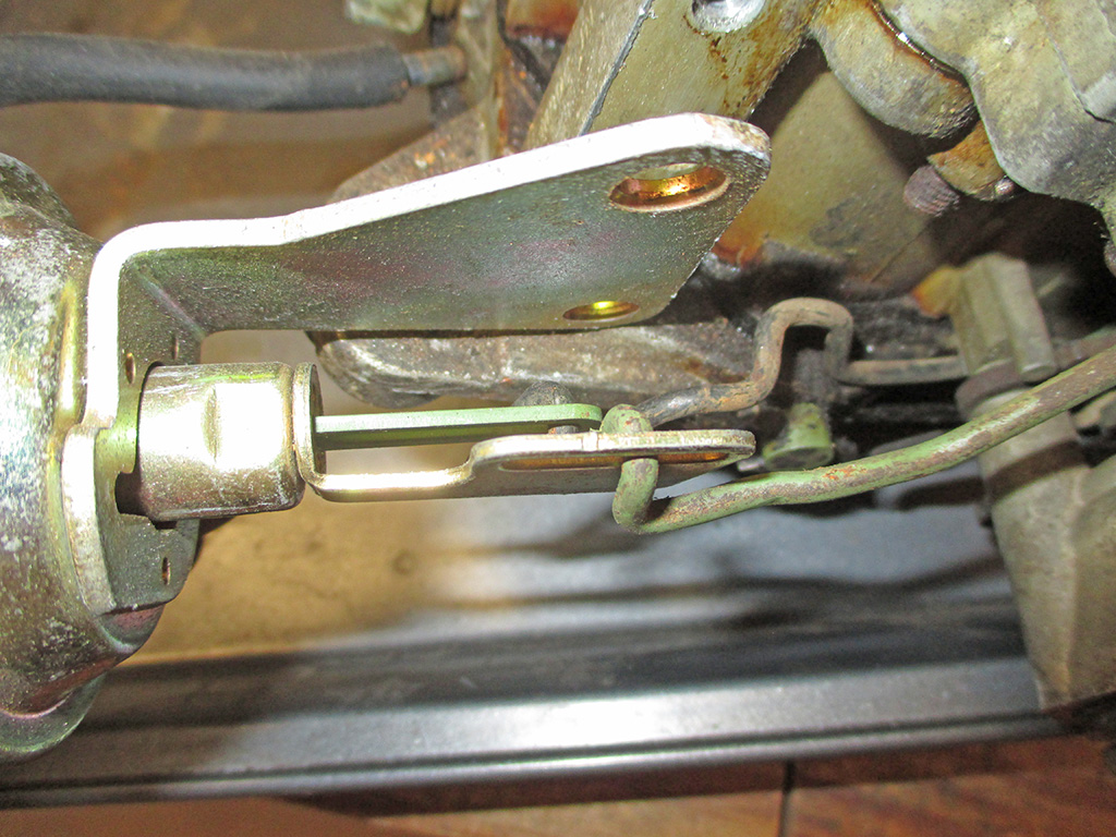
SIDE VIEW
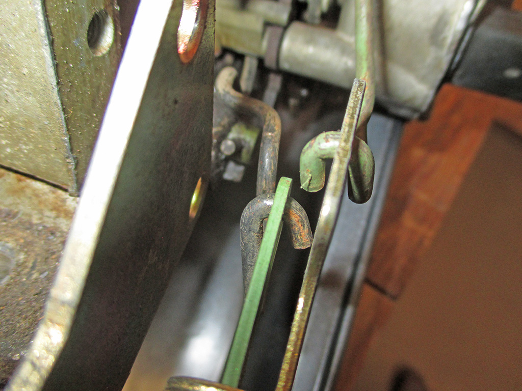
END VIEW
Getting it back on required removing the bakelite electric choke unit, loosening the choke body just enough to hook the rod back through the proper hole, then picking up the secondary butterfly lockout lever that you knocked off in the process and putting it back into position without knocking the rod off again. If you do, well begin all over again and try not to be so clumsy the next time.
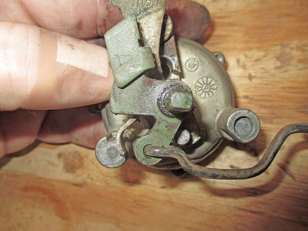
Remember that black rod you had to retrieve with your magnetic pick-up tool? Well, here's where it goes. Only you don't actually get this view. You have to do it by jamming your head into just the right position and then, using the hand that's not maintaining this delicate balancing act, get the damned rod back in the hole again. The clearances between the green linkage and the body of the carburetor are theoretically tight enough to keep the rod from falling out of the hole.
All my futzing around with this little linkage assembly proved that someone at some point bent the black rod to where it had enough room to fall out while I was adjusting things. A little judicious application of pliers and my vise had it straight once more. Also seen here, the relationship between the green choke linkage and the gold choke linkage as well as the stops they use which are cast into the choke housing. I was just a wee bit paranoid about getting everything back together in the proper order during reassembly.
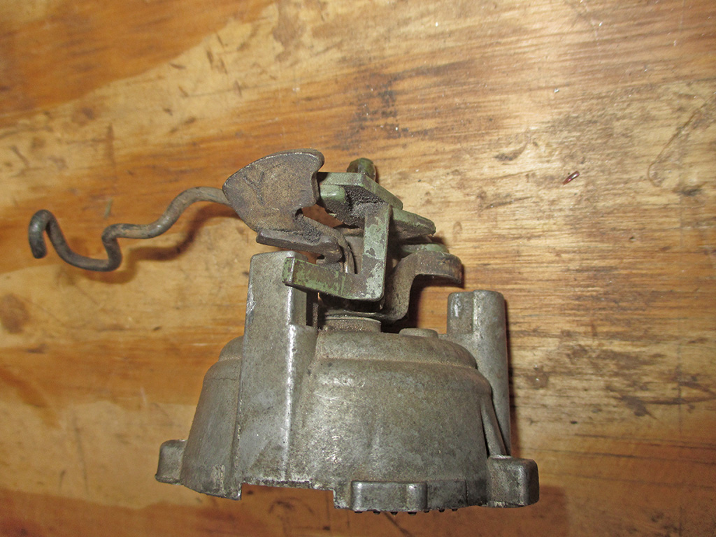
Here's a shot of the choke housing in "as installed" position. This shot also lets me know the relationship between the green choke linkage and the gold choke linkage as well as the stops they use. The only diagrams I could find were (to be kind) "rudimentary" in the detail they provided. So I shot this baby from every angle I could think of.
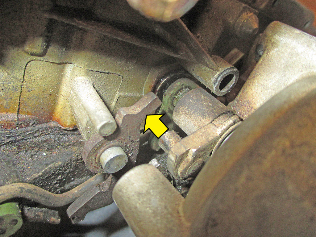
A very important reference shot. This is the secondary butterfly lockout lever. Please note, the cylindrical pivot of the gold choke linkage goes BENEATH THE LEVER as the arrow shows.
I stress this point because it is possible to place the lever in the wrong position beneath the cylindrical pivot of the gold choke linkage. If installed incorrectly, the secondary butterflies will be locked out all the time. When installed properly as indicated, the lockout lever will move as soon as the gold choke linkage moves during engine warm up. Many leave this lever off during a rebuild believing it will prevent the secondaries from opening. This carburetor was designed to do just that... but only when the engine is cold.
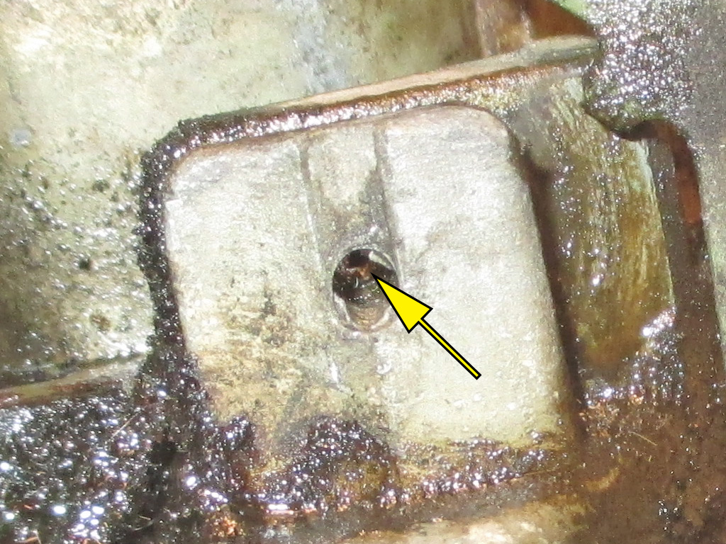
With the choke and associated linkages removed, I turned my attention to the accelerator pump arm. This is held in place by a tiny pin that serves as a pivot point. They give you a new one in the carburetor rebuild kit, but since it doesn't wear, I drive the pin in with a tiny punch until the lever just comes free.
You can replace it if you want to, but by driving it in just enough to release the arm, later on I can wedge a screwdriver between the pin and the air-horn to press it back into position when I reinstall the arm following the rebuild. Also, there are two holes in the arm for the accelerator pump rod. Make sure you make a note or take a photo of which hole the accelerator pump rod goes into.

A shot of the bottom throttle plate. This is more evidence that the van probably is a genuine 78k vehicle. These are the tamper resistant plugs GM decided to press in place over the idle mixture screws so owners could not fiddle with them and increase tailpipe emissions.
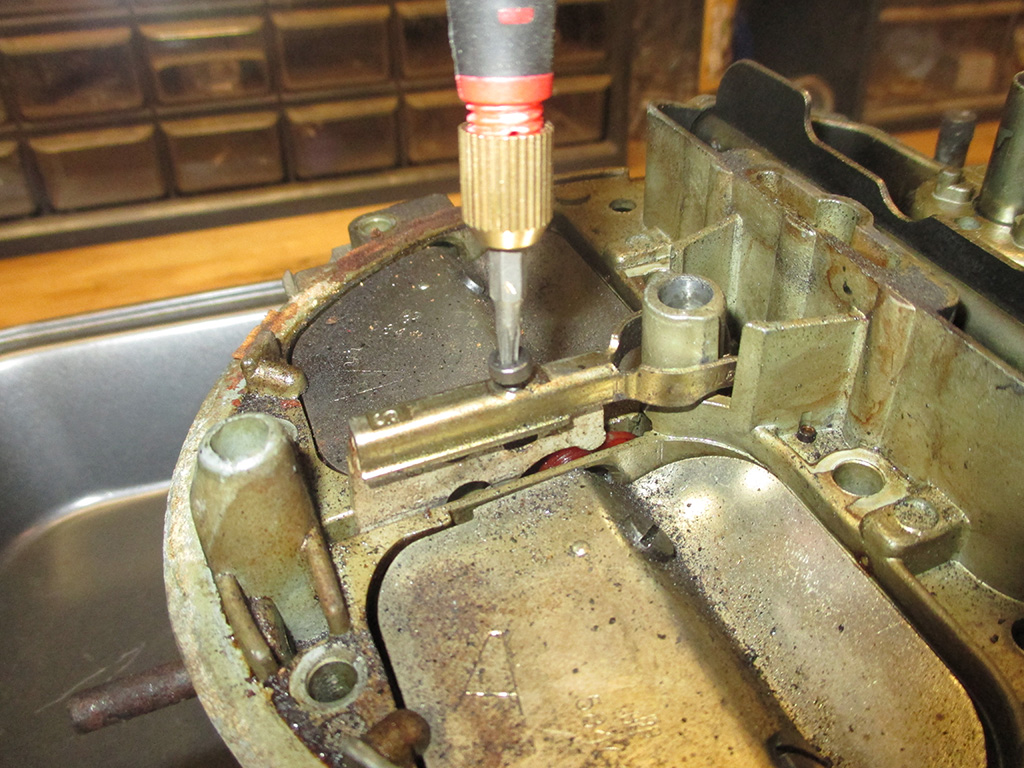
My particular version of this carb used Torx screws throughout. This one took a tiny little #8 tip to remove. I carefully removed the secondary metering rods and carefully set them aside.
Finally I began cracking the screws loose, all 13 of them. I carefully removed and set these aside in an order that made sense to me. The two really long ones go in the back of the carb, the two small ones reside under the choke plate.
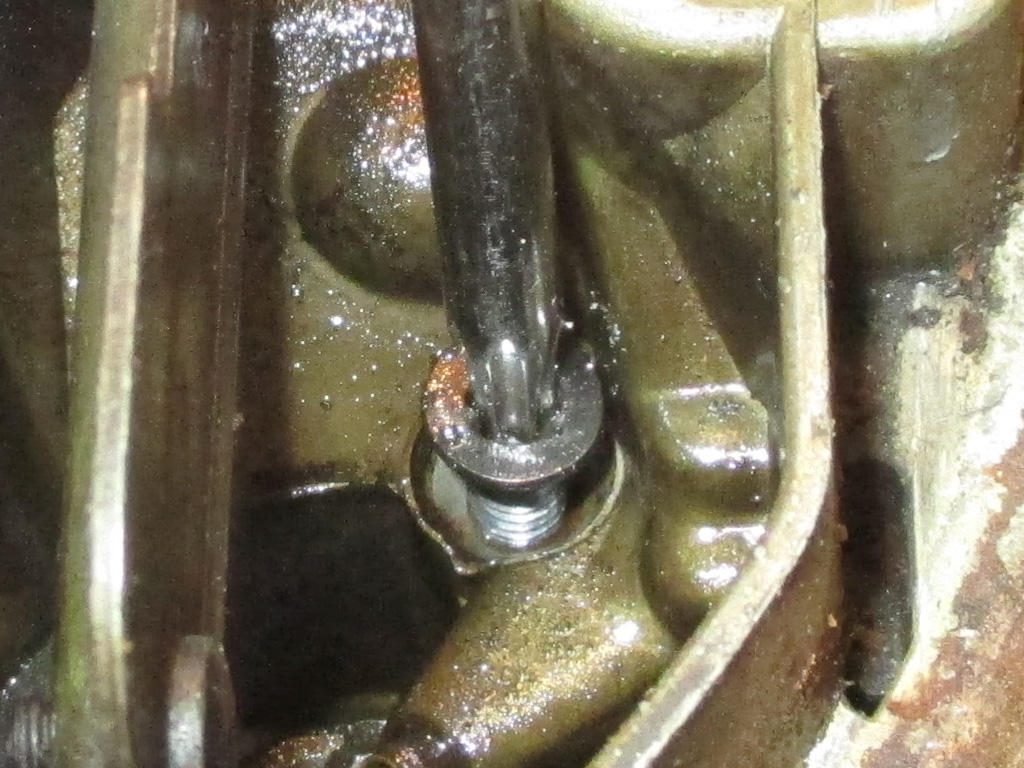
HIDDEN SCREWS
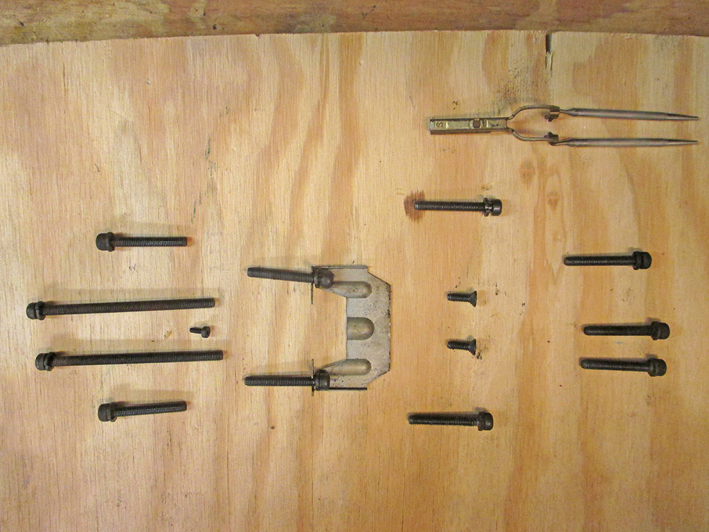
ON DECK
I carefully put the secondary metering rods on this piece of wood for safekeeping. Along with their own very tiny mounting screw. I didn't want that little dude to go missing in the interim.
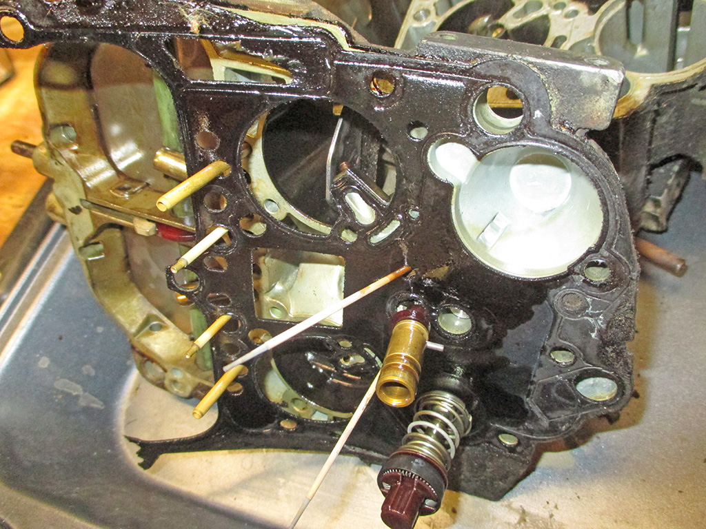
Now I've done it. I actually removed the air horn from the body of the carburetor. This part was a little stubborn and I had to tap very gently around the perimeter of the air horn with a small hammer. Finally though, it relented and I was able to remove the top of the carburetor.
Some good news in this shot. The brass pick up tubes were in place and not laying in the bottom well of the carburetor. I did manage to destroy the gasket, but I've got a new on in the rebuild kit, so it's not really a problem. Also nothing really looks all that dirty. I know the gasket was leaking, so I suspect a needle valve or float problem, but overall I'm encouraged by what I see.
Here I'm extracting the primary metering rods (and power piston) from the gasket. The gasket actually has a slit which enables you to maneuver it around the rods. The gasket was still flexible enough to allow me to do this without ripping or splitting. This was good practice since I have to repeat the whole process in reverse when it comes time for reassembly.
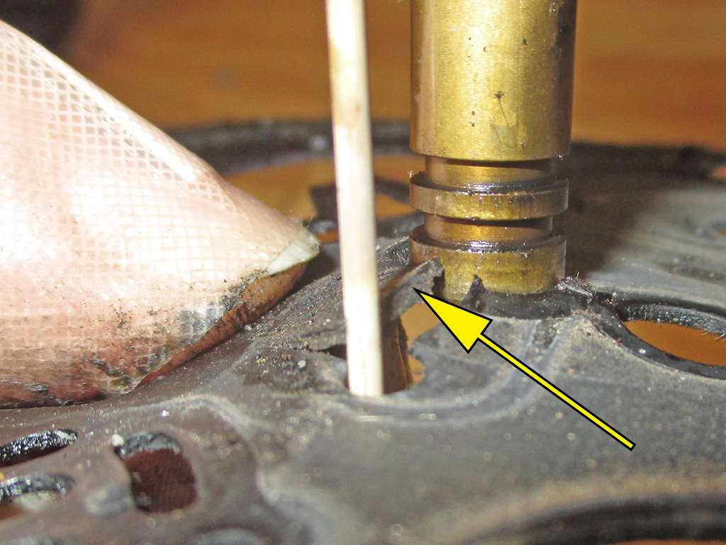
GASKET
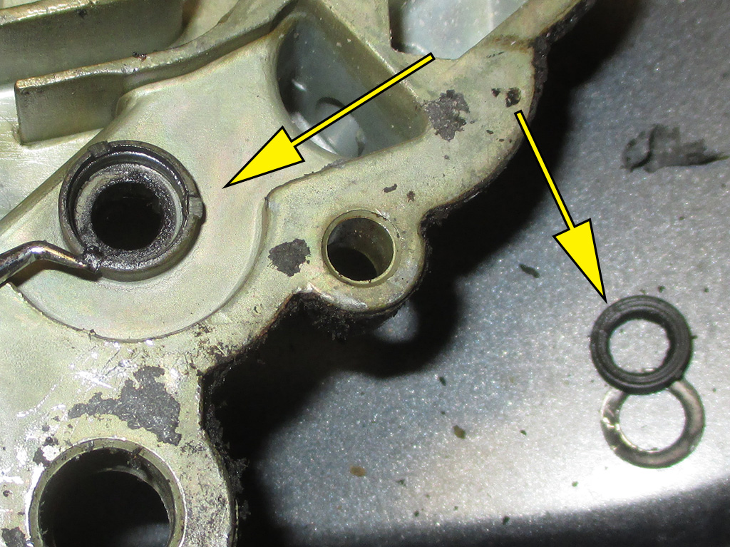
SEALS
Underneath shot of the air horn (or upper third of the carb body if you prefer) showing the hole for the accelerator pump rod, left arrow. This hole has a rubber gasket and retainer ring, right arrow. This part had deteriorated to the extent that it was leaking gas onto the top of the carb. It will be replaced as the carburetor is rebuilt.
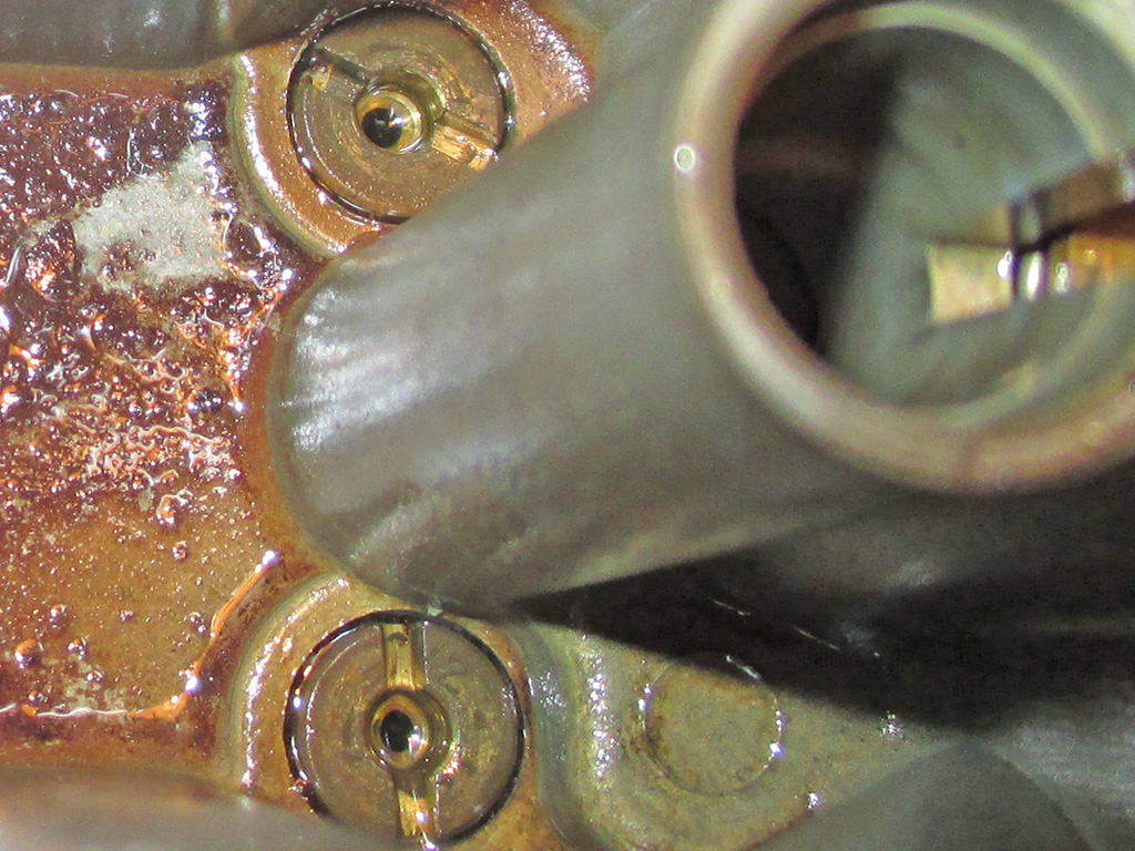
Now we're getting down to brass jets! What was that I said about not being all that dirty? Quadrajet carbs have a centrally located float which lives in the area shown here. A nice thick layer of reddish-brown gunk greeted me once I got to this point, covering the bottom of the float bowl. The primary jets are to the right, and have slots in them for using a slotted screwdriver for removal/installation.
The clean mark to the left of one of the primary jets was where I tested how thick the gunk was with a popsicle stick. You don't want to scratch things up with a screwdriver. The cylinder to the right of them is where the power valve or power piston goes. After seeing this, I do not regret pulling the carb for cleaning. I'm not sure this is the cause of my problems, but it sure can't be helping things much.
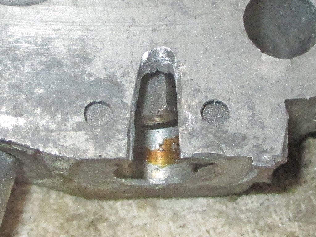
A virgin no more. I used Mr. Dremel equipped with a cut off wheel to carefully cut through the aluminum of the throttle plate and just barely into the steel of the cap. When you start seeing sparks, you know you are hitting steel with the cut off wheel. I've seen carbs where folks have used a hacksaw or small chisel to do the same. I prefer to make a neat and professional looking job of it. By cutting a small slot in the cap, I used a very small chisel to tap the cap out of the aluminum. It really wasn't hard to do at all.
This was necessary due to the fact that I wanted to soak everything in the carburetor cleaner and I need to remove the idle adjustment screws so the cleaner can get into all the passages. I gently seated each screw before completely removing them. Each one had been turned out 1 and 3/4 of a turn.
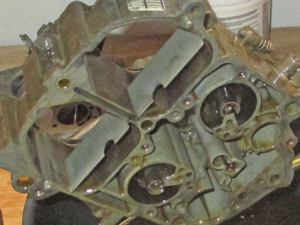
CHEMDIP! This is the shit right here. If all the warnings on the label aren't enough to make you use caution, then the stench probably will be. I carefully poured the Chemdip into a cast-off soup pot which gave me room to submerge the pieces of the carb completely. It also had a lid to help contain the noxious fumes emanating from the cleaner.
I wanted this baby clean. To that end, I left each part of the carb soak for 24 hours. When I pulled it out of the soup, the black carbon was running right off the aluminum. A quick blast of brake cleaner made everything look brand new again.
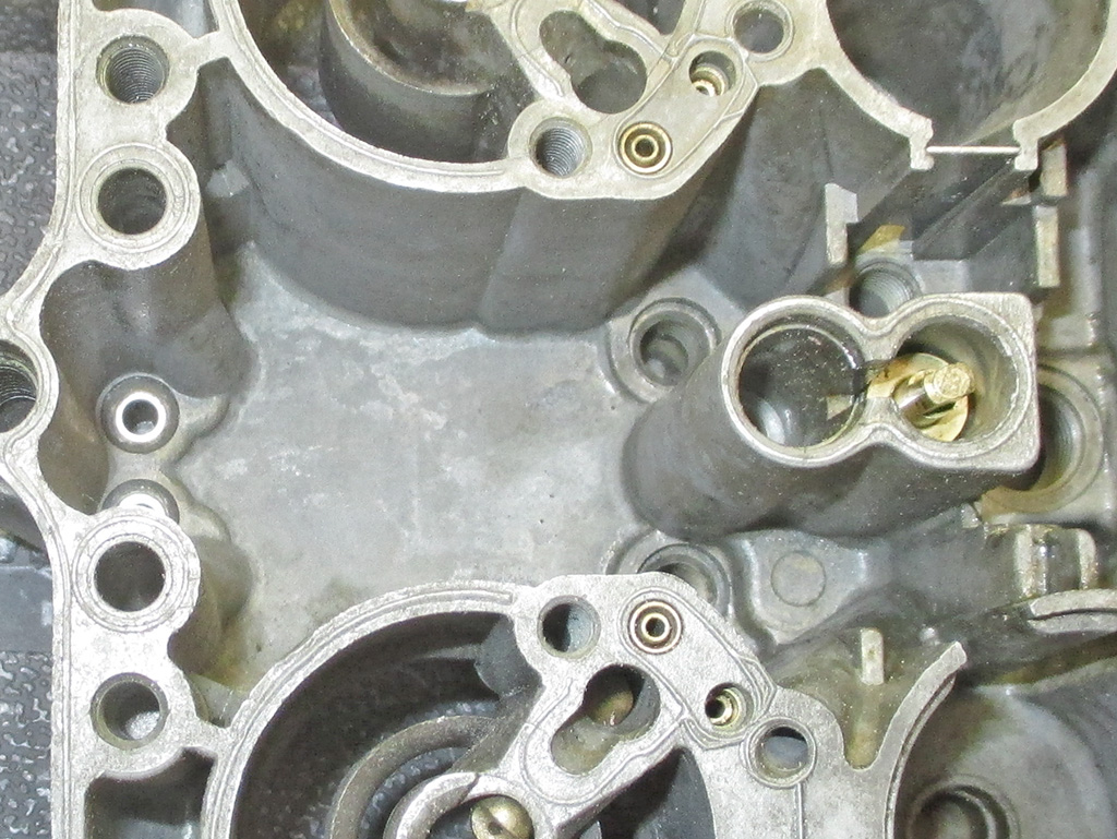
Here we are fresh from the Chemdip followed up with brake cleaner. Certainly a far cry from where I started out. No more fuel residue and at this point I haven't even reinstalled the primary jets yet. This is where I can put my meticulousness to good use. It also helps to be a perfectionist, since you have to take several measurements such as checking the float level after installation of the new float and needle valve assembly.
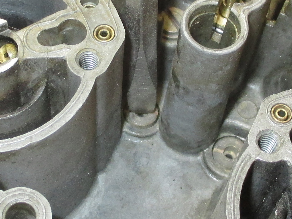
Since these were one of the last things I removed before the Chemdip, they are some of the first to be reassembled. You have to be sure you use a screwdriver with a wide enough blade to grab each slot fully. Being anal retentive, I put the screwdriver in my vise and dressed the tip with a file, making sure I had squared up the rounded off edges. I attempted to make them just as tight as the force I had to apply when removing them.
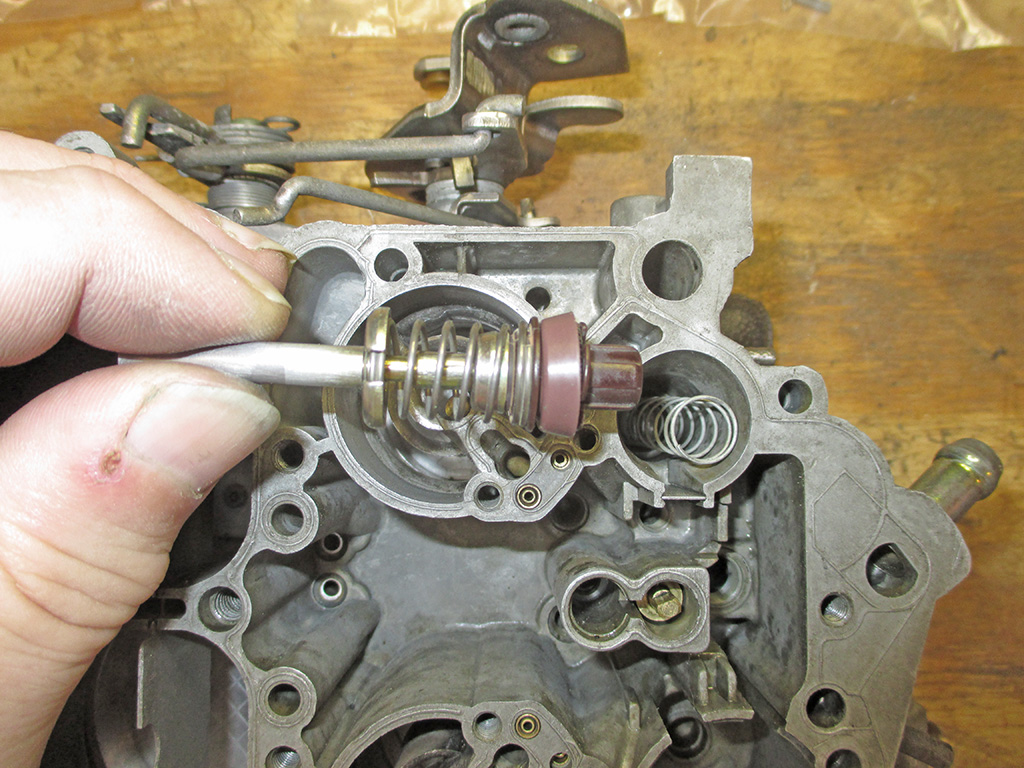
Everything in the world just keeps getting cheaper, or perhaps more accurately, de-contented. In the past, you would get a new accelerator pump as seen here... the whole shebang. Out with the old, in with the new, done. Not any more.
Now you get a new tiny circular spring and a new rubber cup! That's it. Granted it may be all that wears and all that needs to be replaced, but there's a whole lot more "Dicking Around" doing it this way. They give you a small plastic cone that you lubricate, put it over the plastic tip of the assembly and stretch the cup up and over the plastic tip. Then you take a small pick took and worry the spring into place. Wonderful.
Instead of the old brass valve seat and the silver needle valve which hung suspended from the float, I was faced with... with this. I wasn't sure what to make of it at first. I compared the height of this with the old seat and valve and they looked to be the same. My camera makes this look a lot shorter than it really is.
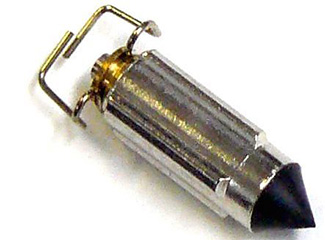
VINTAGE VALVE
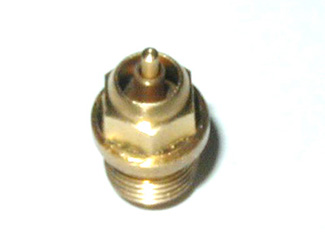
UPDATED VALVE
I installed it with a washer underneath and hung the new float in position. I checked the measurements listed for my carb using the ruler provided in the kit. I checked it several different times to be sure I was doing it the right way. In the end, the measurement was spot on and I did not need to make any adjustments to the float.
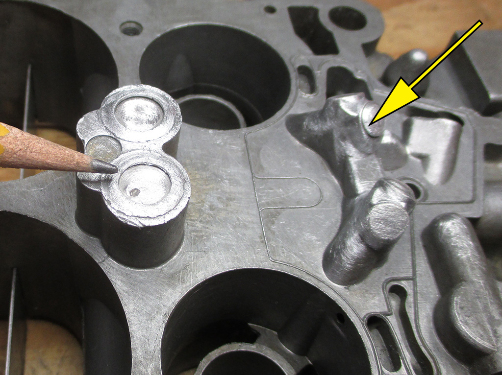
At the onset of MY GREAT CARBURETOR ADVENTURE, I'd wondered why there was so little gas coming out of the carb, since I'd driven the van the day before. Evidently when the factory drilled the primary and secondary jets, they used lead plugs to seal the machining holes left behind.
The primary well plugs (yellow arrow) are notorious for this, leaking gas into the intake. Then you have to crank the engine enough for the fuel pump to refill the float bowl. I figured I'd fix this too, since I'm up to my eyeballs already. The pencil point shows where the secondary plugs are, they got the treatment as well. I lightly sanded all the surfaces with 100 grit sandpaper so the epoxy I have would have some tooth to bond to.
Some folks use JB Weld, others say it won't hold up. I decided to use a putty form of epoxy designed for sealing leaky fuel tanks. I figured since the float bowl is just a tiny fuel tank, this stuff would be just the ticket I need.
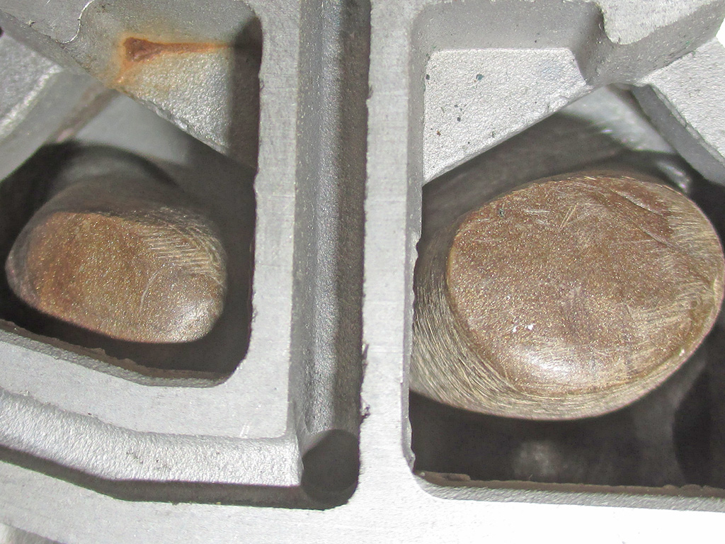
Once again, I was in the zone (and fighting with super sticky epoxy), so only one shot of the end result. This stuff comes in a tube about 5 inches long, brown outside, tan inside. You cut off what you need the knead it to one consistant color. This stuff stuck like crazy to the rubber gloves I was wearing. I used the plastic wrap I peeled off the stuff to do my final shaping of the epoxy.
I let everything cure for 48 hours even though the package says full cure in 24. I didn't realize how close the tolerances were until I tried to mount the throttle plate to this part of the carb. I sanded the epoxy, did a test fit (several times) until it fit like it did from the factory.
My sincere hope is that this repair should have fixed the leaky well plugs. I've read where the permanent fix is to drill out the plugs, tap the holes and thread in short screws, sealing the threads with epoxy. Knowing my luck, I'd probably split the aluminum and ruin the carb body, so I did it this way. Will it last? Good question. I guess time will tell, but this epoxy is designed to work with fuel and within the temperature range I think the under hood area sees.
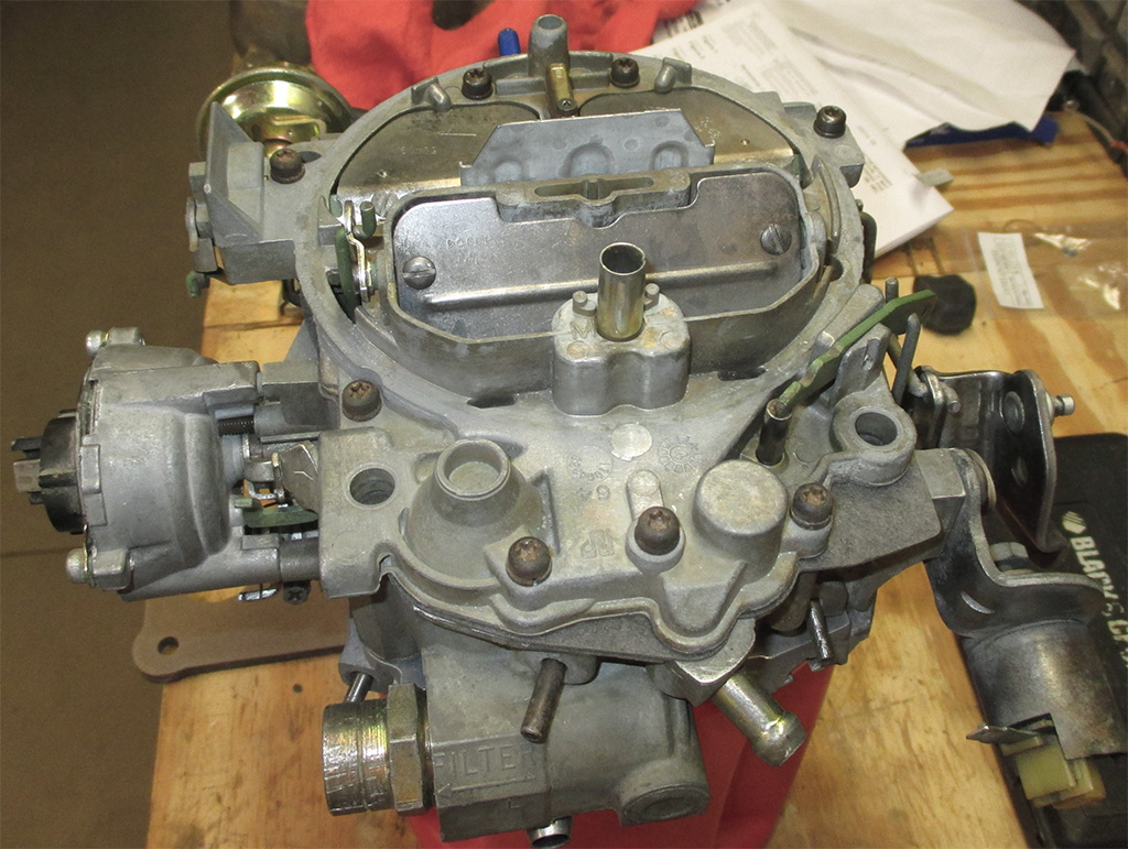
Tah-dah! Here she is boys. Clean as a whistle and 3 turns out on each idle adjustment screw, which should be enough to get it started. I figure I've saved money by rebuilding the carb the van came with instead of buying a replacement. I spent roughly $40 bucks on the rebuild kit and the new float.
All that remains is to plop it on, bolt it down and fire it up. Then I'll see what improvements have been made. I hope mileage is up a bit since I'm not wasting a float bowl of fuel each time the van sits for a day or two.
With the carb finished I only had two other items to address. I bought a cheap vacuum brake locally. This was a mistake. It had a larger opening in the vacuum hose nipple and the slotted arm which operates the black choke rod choke was shorter. I did not realize this immediately. I bent the choke rod to compensate, but it was still no-go. After much futzing around, I went to NAPA and ordered the right unit for... $75 bucks! I should've brought some Vaseline with me, but I did receive the proper part and only had to re-bend the choke rod back to its original shape to get things working again. Sheesh!
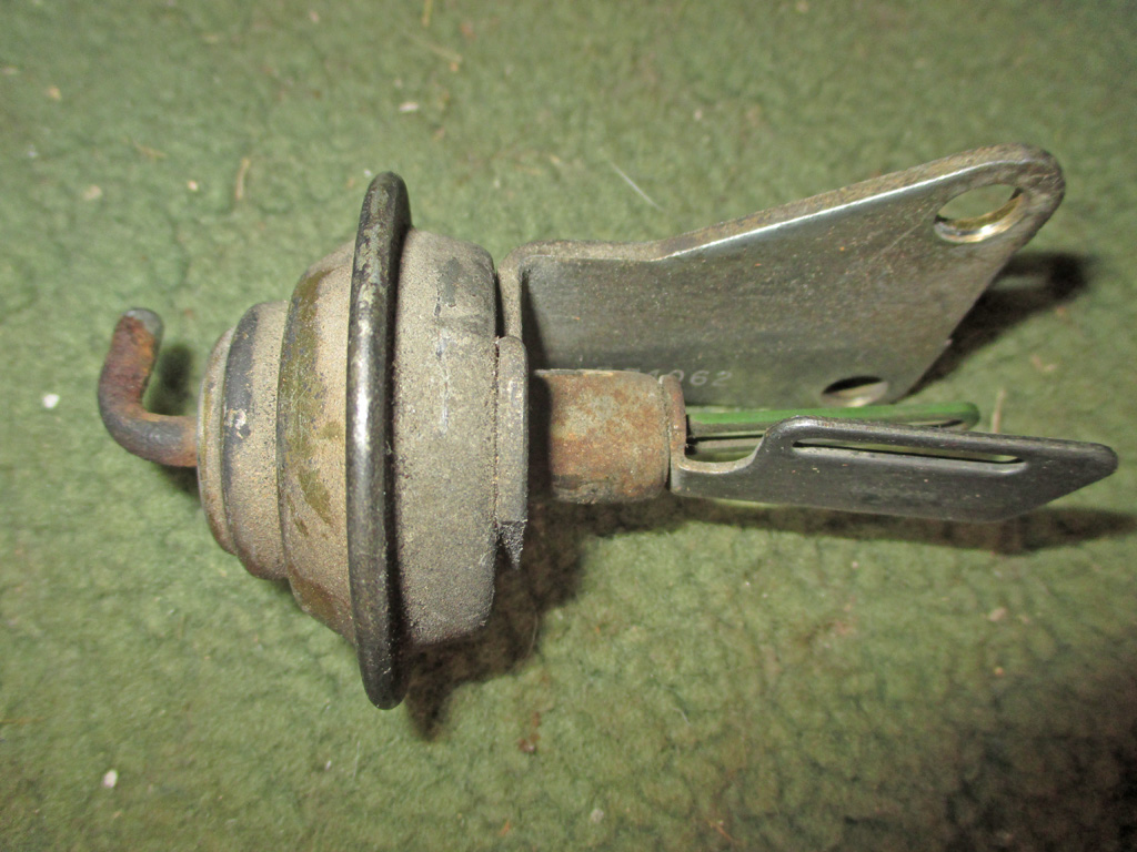
VACUUM BRAKE
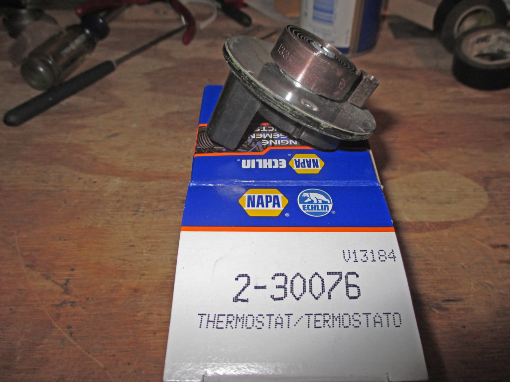
ELECTRIC CHOKE
Now, all the vacuum brake does is crack the choke open just a bit once the engine fires. The electric choke coil slowly opens it up the rest of the way as the bimetallic spring heats up. I tried to use the one I had, but if I set it rich enough to run the van cold, it wouldn't open up all the way. Another couple of weeks of fiddling did nothing, so reluctantly I once again made a pilgrimage to the bank of NAPA. This time they lightened my wallet to the tune of $66 bucks! But they had it in stock, so what the hell I thought and forked over the long green. I installed the new coil and once adjusted, my van starts when cold, accelerates without stalling and opens fully when the engine is fully warmed up. Christ I get stubborn sometimes.
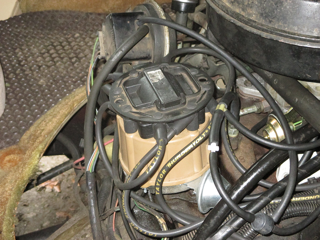
So... I'd rebuilt the carburetor, changed the spark plugs, changed the air and fuel filters, changed the distributor cap and rotor and... I still had issues! If I tried to "jump on it" to merge into an opening in traffic, I'd be rewarded with a backfire through the carb and a total loss of power and forward momentum. Sitting at a traffic light, it would lope and rock like I'd installed a 3/4 race cam. Under easy acceleration on a slight incline or a flat stretch of highway, I thought I'd run into a bad stretch of highway - until I discovered letting off the gas pedal smoothed out the highway immediately. I was getting pretty pissed off at the whole affair.
Back to the internet. I read where old, worn, or damaged plug wires had given other folks the same problems. Replacing the spark plug wires cured all their woes. But you have to use quality wires, not cheap junk. Great! So I dropped $62 bucks on a set of Taylor "ThunderVolt" 8.2 wires that are supposed to only have 40 ohms of resistance per foot. I was stunned at the results. Chugging at stoplights... Gone! Rough-road simulation... Gone! Acceleration up hills... Back! New quality plug wires did indeed make all the difference. One last thing. Make sure you replace one plug wire at a time. So you don't cross any wires or anything. Because that would be rather dumb.
Air Conditioning
April 2015
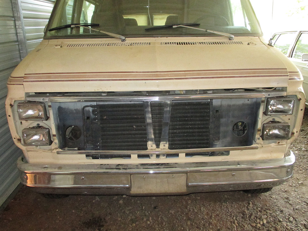
In search of the Comfort Zone. No, I did not crack up my van. The only ventilation I have in warm weather (in what is essentially a big steel box), is the driver's side window, both front vent windows and the flip-out windows in each rear door. Driving my van in the summer months is not a fun experience.
I need to get the air conditioner back on line. The way that all the refrigerant lines and hoses run, this was the only way for be to gain access. The condenser is right up front and looks like it was replaced at some point in time. I'll probably end up pulling the condenser to give myself enough room to maneuver the line that terminates in a hose fitting.
My goal is to replace all the 1984 vintage hoses with upgraded "barrier hoses" that are compatible with the modern R-134A refrigerant. The molecules of this refrigerant are smaller than the R-12 my van was built with and over time will leak out of the stock hoses. All part of my "do the job once and do it right" philosophy. With summer right around the corner, I figured I better get moving.
Of course just the simple act of disturbing 30 year old plastic is fraught with hazards. Such as the plastic tube/spacer which the trim screw runs through. All I did was use my Torx driver like I did on all the other screws. Evidently, this piece had seen more than its fair use and was not at all happy being disturbed. Now I'm the one who's disturbed, because I have to figure a way to repair this... the boneyards around here aren't exactly overflowing with vintage vans.
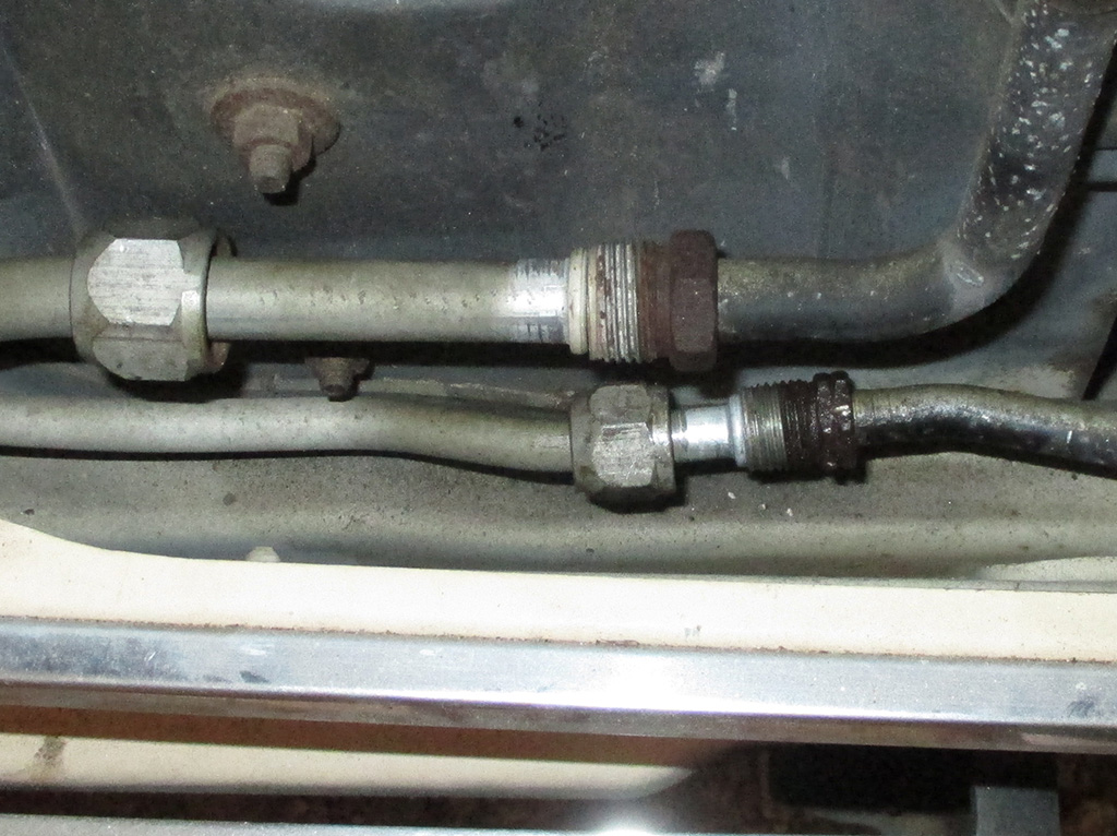
The large line in this shot needs to be replaced as it terminates in a rubber hose at the other end to allow for movement. I disconnected both lines because I will also be upgrading all the O-rings which seal each fitting. The upper line wasn't too bad once I found some wrenches that would fit. The bottom line was a real booger, with barely enough room to loosen the fitting.
As I pondered the situation, it occurred to me that I will probably need to remove the front valance panel to give me enough room to remove the line. Some of the bolts which mount the valance panel are located behind the front bumper! So, what I may try first is removing the top fill panel between the radiator and grille to see if I can thread the condenser up and out of the way.
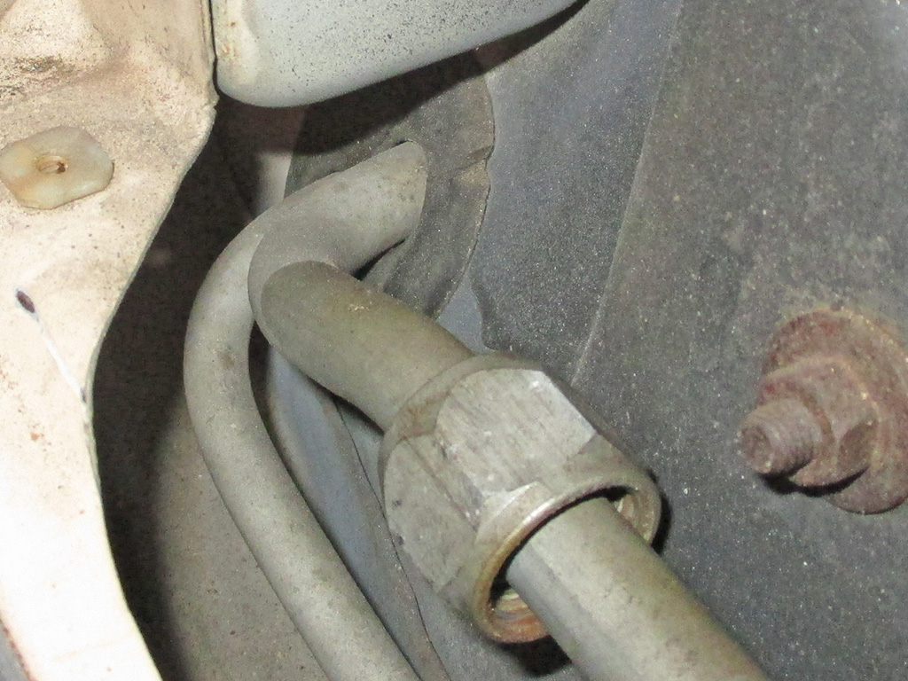
It looks like the grommet allows for the line to be threaded out towards the engine. But this is practically a 90* bend and there isn't all that much room to maneuver in the engine bay. I gained some space by removing the radiator overflow tank and the accumulator, but things are still really tight. If I'm going to get new hoses, I have to have the old ones out to use as patterns. I foolishly thought I'd have these out of here in a couple of hours. Uh... nope, not even close.
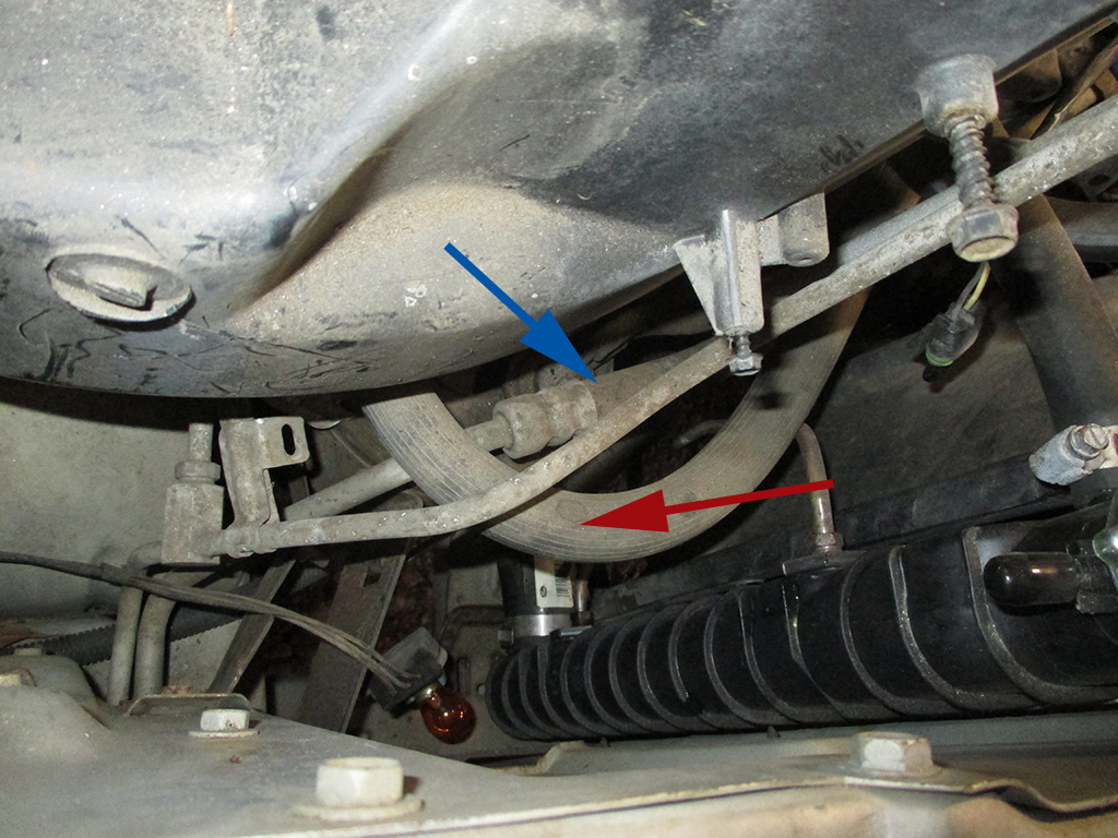
The blue arrow points out the hose running from the condenser up to the compressor. The red arrow shows the hose that runs from the compressor to a line that goes under the evaporator air box towards the back of the van. The smaller line from the condenser runs into a T block, going into the bottom of the evaporator air box with another leg diving down under towards the back of the van. These are all the rubber hoses I have found so far. Finding them and then replacing them are two very different kettles of fish.
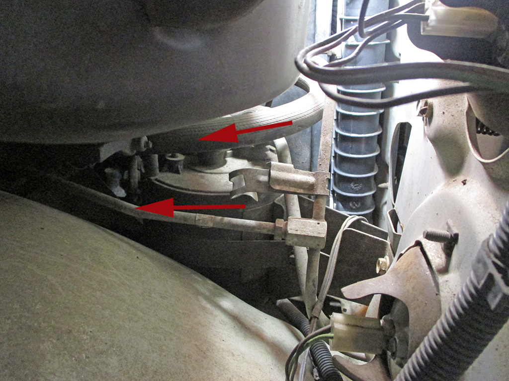
I pulled the right front marker light to get a better look at things. Both of these lines feed the rear A/C unit. The factory only used rubber where vibration and movement of the engine required some flexibility. I'm not sure if the original aluminum lines that run the length of the van are okay.
I've seen kits that use rubber hoses to replace them, but rubber degrades over time and the kit costs about $275 (for Suburbans/Escalades), and nothing is stocked for a van. I've read where the original aluminum lines have been the cause of many leaks due to being exposed to the weather and road salt. I'm hoping my Southern van will be in better shape and can be re-used.
Here's the result of 2 hours disassembly. In looking for replacements on the web, I discovered these are called manifold hoses. Not sure why, but it helps to plug the correct term into a search engine.
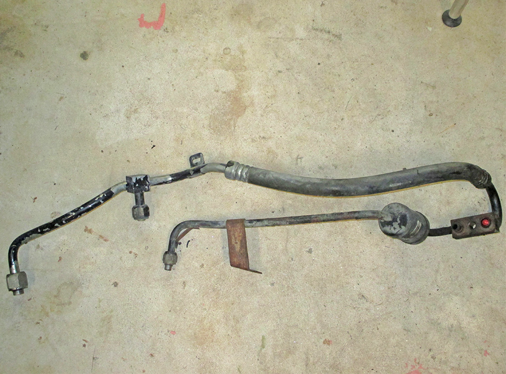
MANIFOLD HOSES
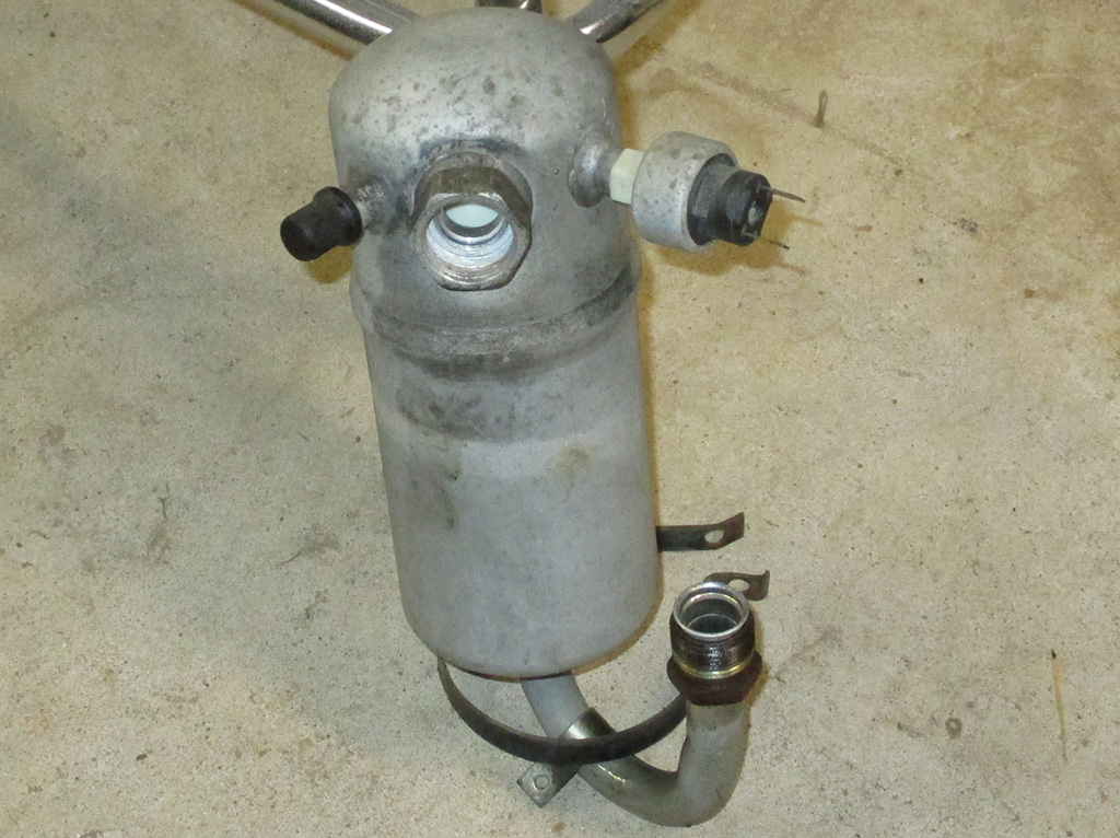
DRYER ACCUMULATOR
After spending a few hours online, I believe I'll have to source my replacement hoses locally. I found one source for classic car AC parts, but pickup trucks was as close as I came to a van. Now all I have to do is remove the rest of the originals.
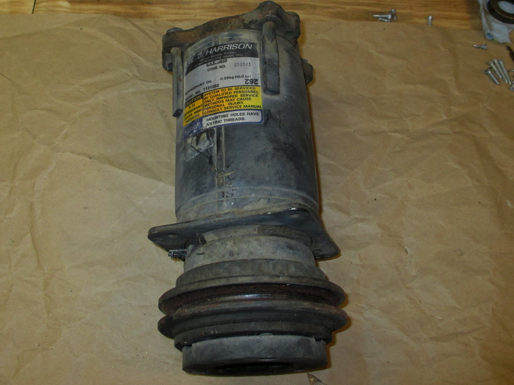
This is the compressor, the heart of the whole system. Rock Auto has a kit with the compressor, orifice tube and expansion valve for the best price I've seen. I think I'll replace the evaporator while I'm at it, since the old one would need to be flushed and most are designed with a well at the bottom making flushing difficult.
It's also the hardest component to get at, yet contributes greatly to the efficiency of the newer refrigerant. I'd rather do it now, then try and skate by with the old one and have to tear everything apart again. Since my van has rear A/C, I'll need to flush the rear evaporator as well.
An article on the chevytalk.org website brought these folks: Automotive Air Conditioning Information Forum (discussions covering all aspects of automotive air conditioning) to my attention. The saying "cleanliness is next to godliness" evidently applies to all the components of the A/C refrigerant system. Several different solvents can be used (including lacquer thinner) and you cannot flush too much or blow-out too much. If you use shop air to blow out the lines after flushing them, (ensuring all the flushing chemical has evaporated thoroughly), you have to make sure you have a moisture filter in the line.
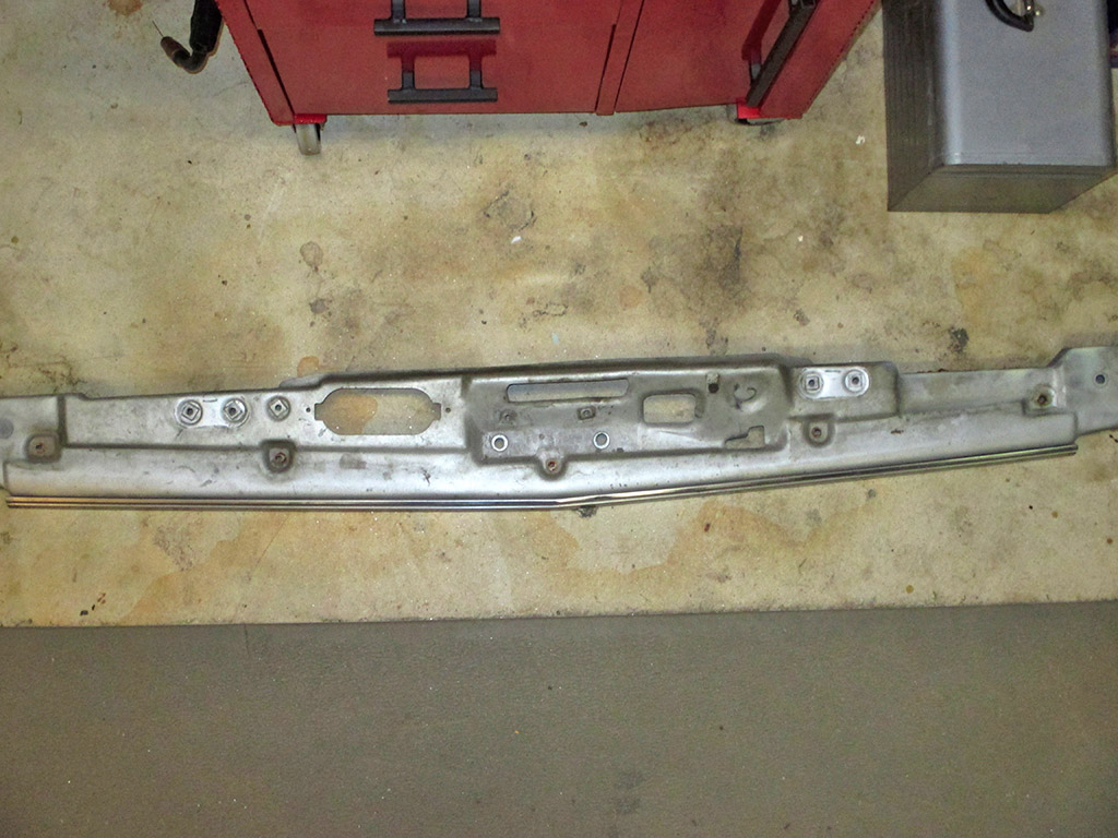
After sitting on a stool and staring at my condenser situation for a bit, I replaced all the bolts I had removed from the front valence panel between the bumper and the grille. Instead, I switched tactics and removed the bolts (there are about a dozen of them) holding the top panel. This panel bridges the gap between the grille and the radiator and provides a mounting point for the center support and hood latch. It's not really bare metal, but painted a silver that showed up like bare metal in my flash.
Of note in this shot is an oval opening to the left of the hood latch which as two threaded holes to either side. This is for the fresh air tube which is missing from my van. I have an air cleaner with the hose mounting point, but I'll need to procure a replacement fresh air tube, which will help power a bit and mileage. With this baby I need all the mileage boosting tricks available to me.
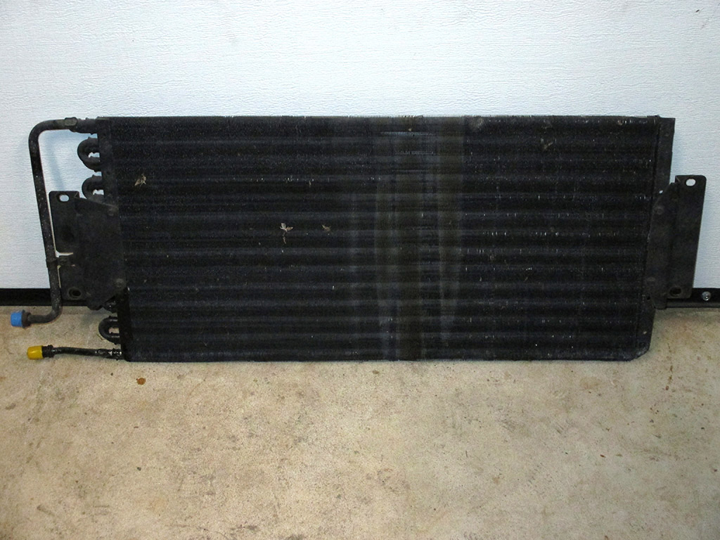
Here's the condenser, the heat exchanger that sits right behind the grille. This was my motivation for removal of the top panel seen in the above shot. This unit looks relatively new in comparison the the rest of the stuff on my van so this will be flushed and re-used for this project.
I've read where the "tube & fin" style of condenser is less efficient with the newer refrigerant, but I'm on a tight budget here, so I'm using what I've already got, unless this proves to be damaged somewhere I can't see.
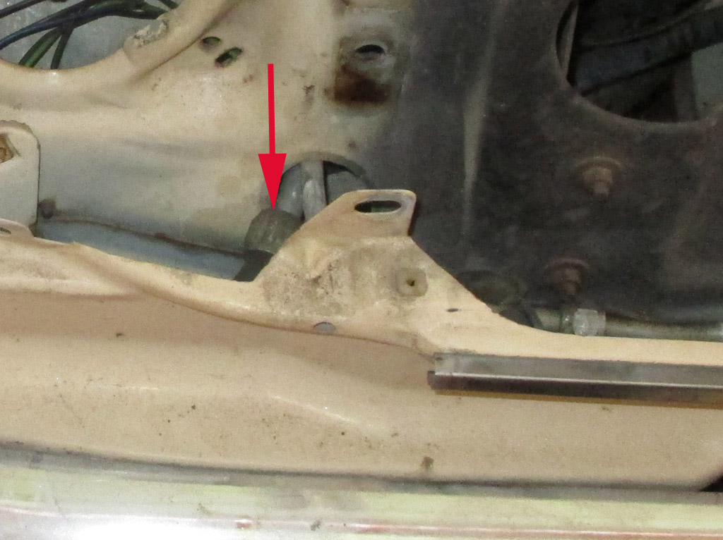
This was the hose that had been fighting me for some time. I got home from work early on Friday and tackled it again. If you look closely to the right of the headlights, you can see a ghost outline of another vertical support I took out in addition to the lower headlight.
The U-bend in the hard line was what was giving me all the problems. The arrow illustrates where the other end of the line is. I knew the small fitting was what needed to go through the hole but getting it lined up properly was insane!
This is the "orifice tube." The orifice tube acts as a filter to keep metal shavings and other stuff out of the rest of the system. I've had compressors fail and the orifice tube would be caked with a silver slurry of metal shavings and compressor oil. This one really doesn't look too bad.
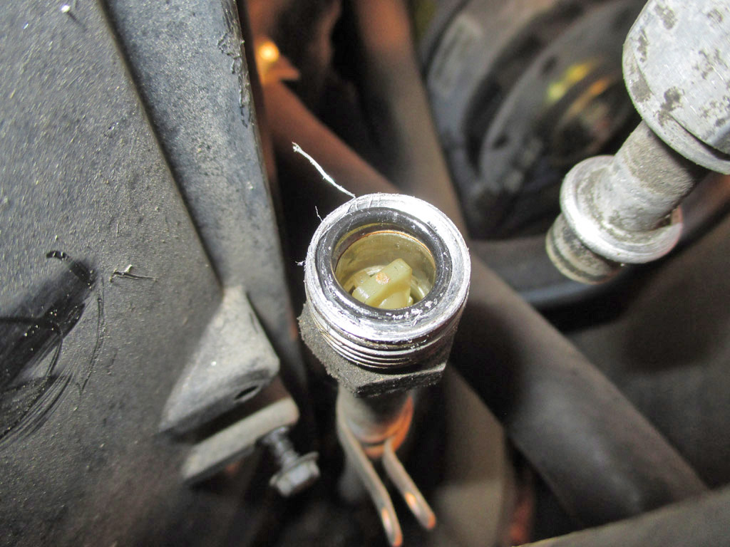
TUBE IN PLACE
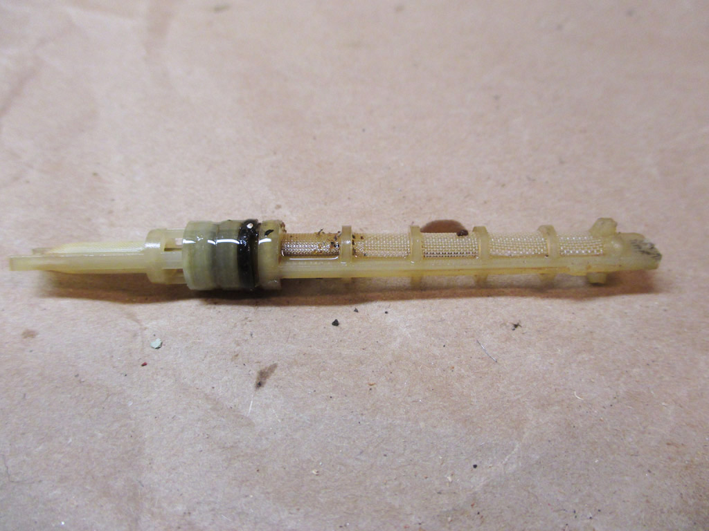
TUBE REMOVED
I know for a fact the compressor I pulled off the van was not locked up as I can turn it by hand. I may end up keeping it as a spare and just forgo the core charge. The stringy stuff looks like teflon tape indicative of a leak at some point in the past.
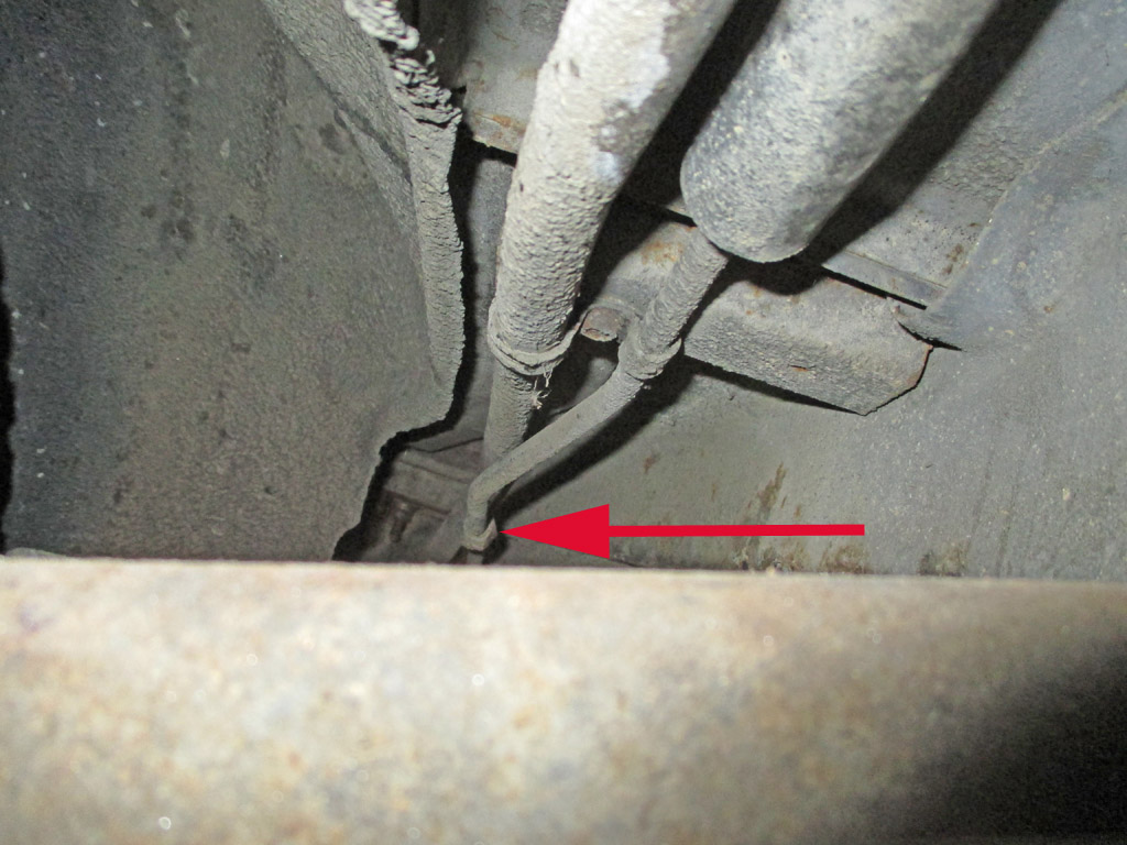
The narrow hard line that runs to the evaporator actually has a fitting (red arrow), where it can be opened if need be. The larger of the two lines terminates in a rubber line with only one fitting... where it connects to the T-fitting of the manifold lines.
So... the whole project came to a screeching halt. I can either ignore it and put up with the original hose leaking the newer freon. I can fork over the cash for the replacement rubber lines, which will have to be custom made. Or... I can cut the aluminum tubing, put fittings on each end, creating the same type of fitting the factory used on the thin hard line. Beautiful.
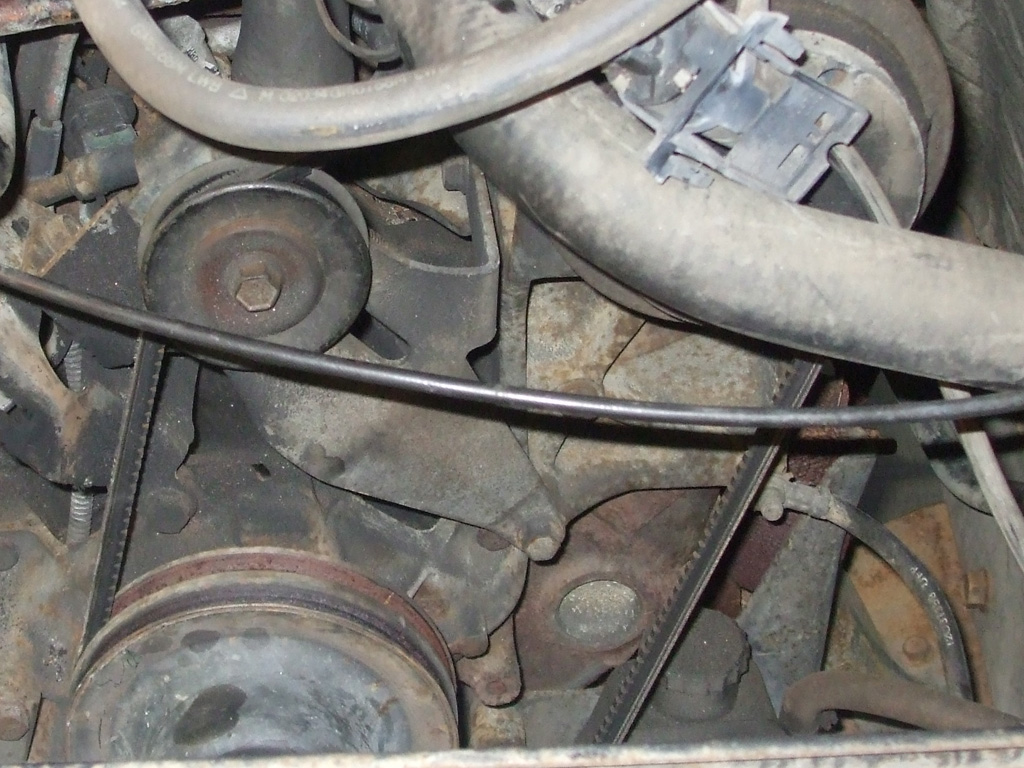
As I ready my van for A/C I realized I needed to reinstall the idler pulley I removed some time ago. This is where it really pays to take photos of everything. I turned this little assembly every which way and couldn't dope out how it had been originally installed.
I pulled out my phone-book-sized factory service manual and... was stunned that there was no A/C diagram featuring this assembly. Thankfully I had the foresight to take lots of pictures when I replaced the water pump. Lo and behold there was the mysterious assembly in all its glory. Now all I have to do is find the hardware, which I no doubt put in a safe place several months ago.
I wanted to move my van up to our carport (with a concrete floor) so I can examine the lines the length of the van on my creeper. Months ago I purchased a new master cylinder because right now my van has no brakes to speak of. Might as well slap it in now, so I can move the van and keep on keepin' on. Naturally, I simply cannot bolt new parts onto rusty parts, so this means it's time for a clean up and touch up. Then I can bench-bleed the master cylinder and mount it.
Wordless Mechanic:
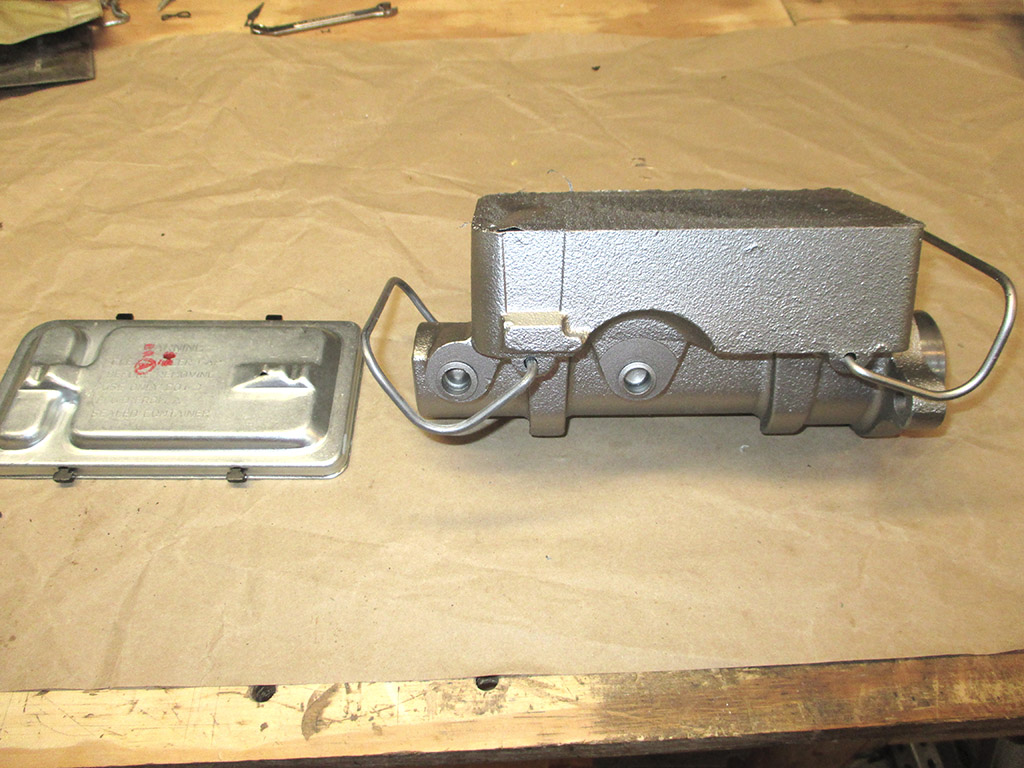
Step 1
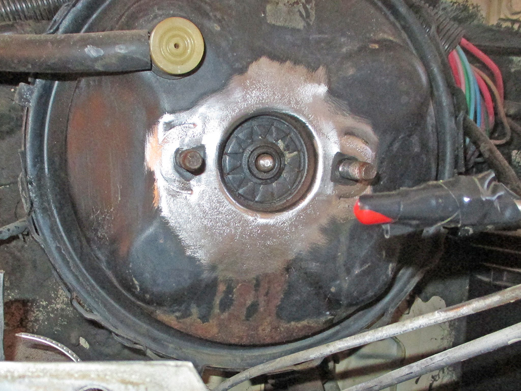
Step 2
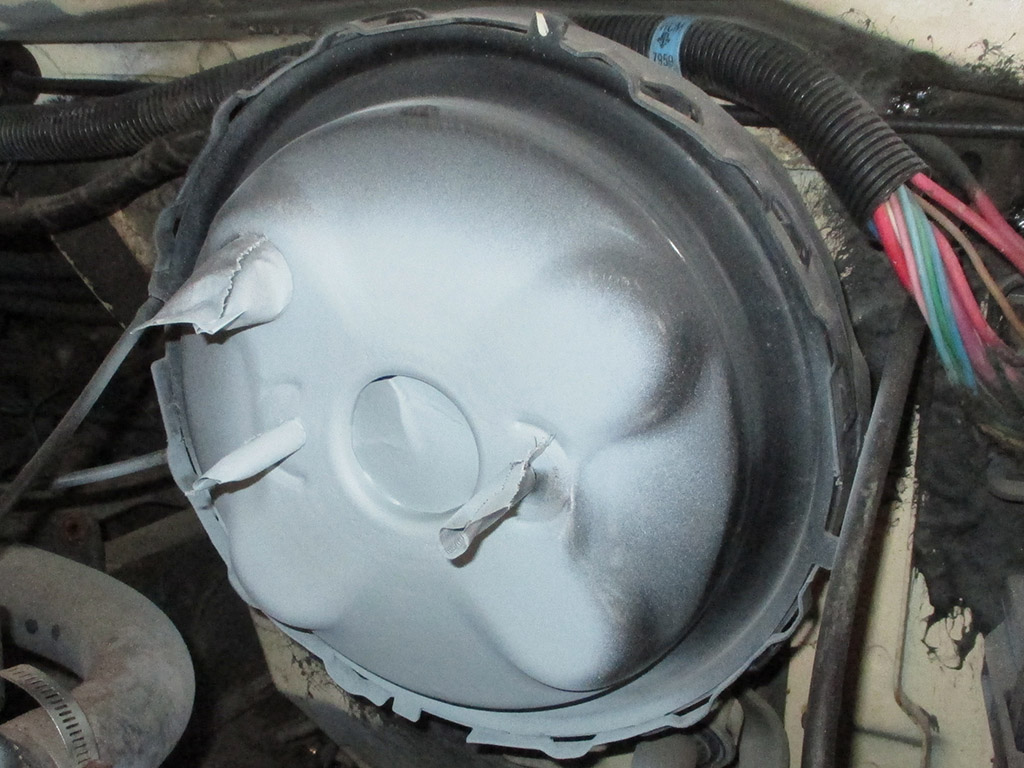
Step 3
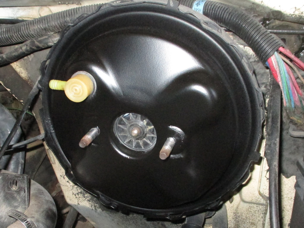
Step 4
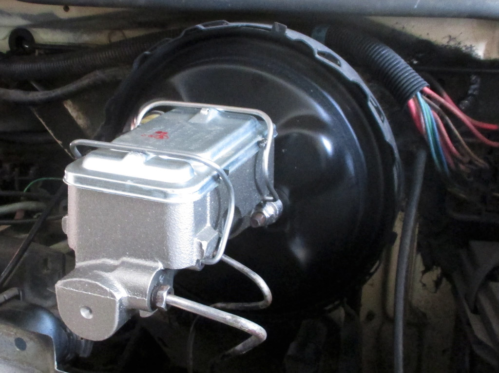
Step 5
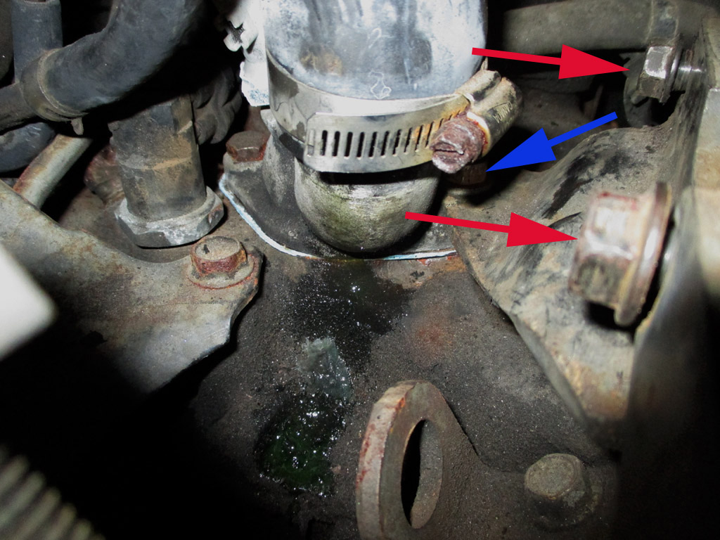
I found the hardware and got to work. Of course the idler pulley bracket mates up with another support bracket bolted (blue arrow), to the thermostat housing. But the side bolt holes in this secondary bracket (red arrows) wouldn't line up. I removed the bracket, drilled one hole the next size up and tried again. The bracket was too high. I removed the bracket, the stud that mounts the thermostat housing to the intake manifold and used a bolt to mount the bracket and the thermostat housing instead.
This lowered the bracket enough for the side bolts to line up. I came back after lunch to find I'd created a nice antifreeze leak for myself. I drained a gallon of antifreeze (the drain aims right at the frame of the van for even more fun) and removed the a/c bracket (again) and thermostat housing. Now I get to clean up all the gasket surfaces and then put everything back together again.
The plan now is to mount the thermostat housing to the intake (sans gasket), then mount the side bracket, then see how big a gap I need to fill between the bracket and the housing. Once I solve that riddle, I can put this whole mess back together and THEN go back to the idler pulley assembly that launched me on this little sojourn through the engine compartment.
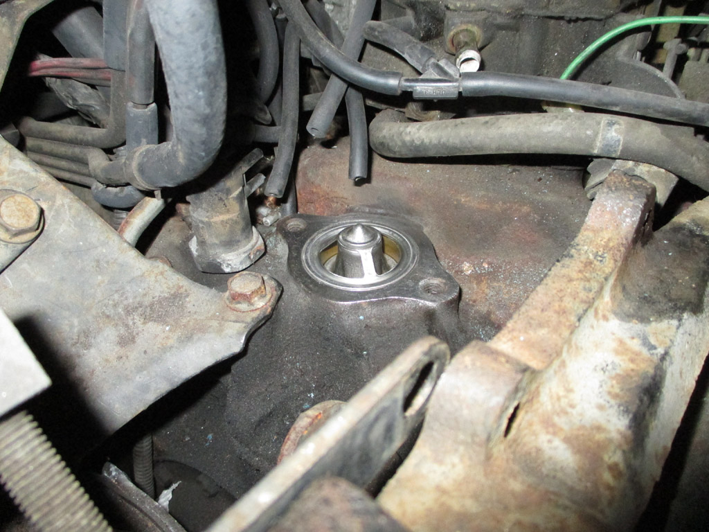
There are times I really wish Mr. Murphy would go pester somebody else... just for the sheer novelty of it. I initially thought I'd cracked the thermostat housing. [Years ago, I did crack an intake manifold by accidentally over-tightening a bolt] I pulled the housing and got it super-clean with a wire brush and brake cleaner. I examined it standing in the bright sun, and saw no damage, so I guess tightening the one bolt made the gasket weep? I'm supposed to be working on the A/C system and here I am, off the rails yet again.
When I wiped the antifreeze off the base of the flange, it re-appeared as if there was a crack in the front of the thermostat housing. After cleaning everything thoroughly I took some "Macro" close ups with my camera. Just like out in the sun, no cracks.
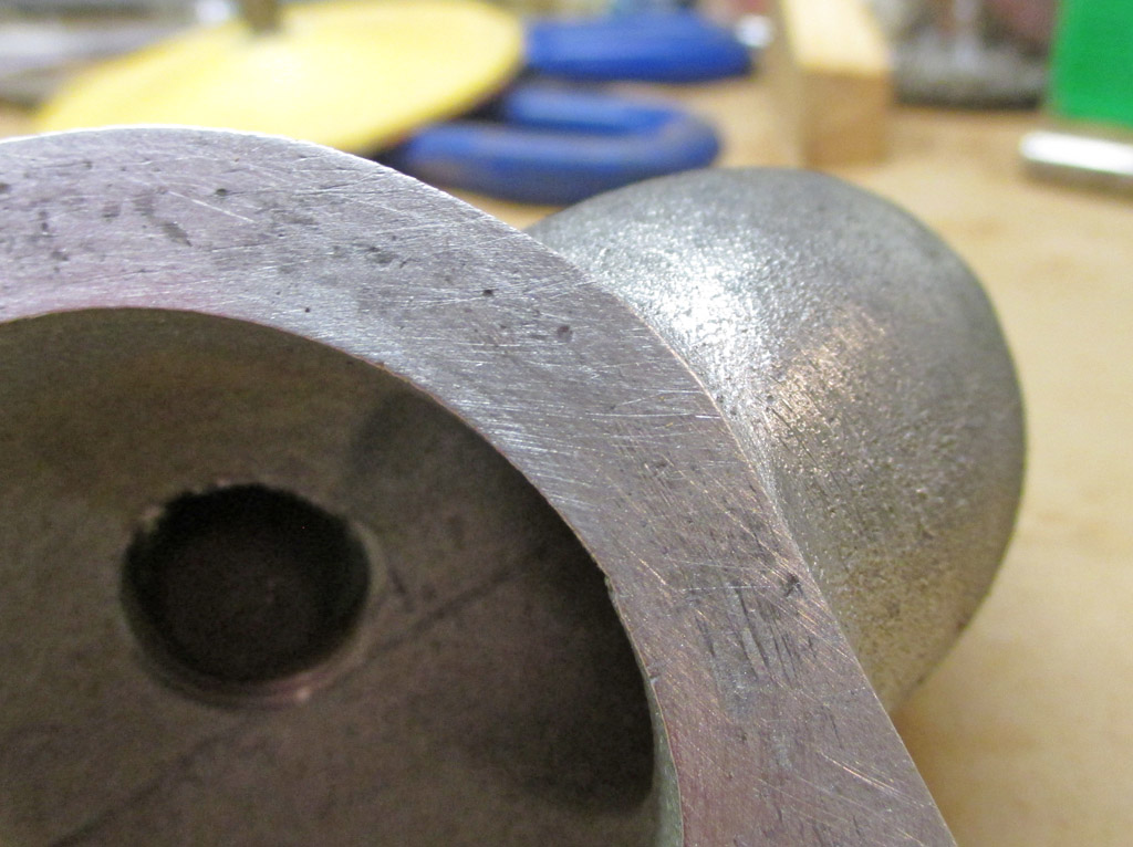
OKAY HERE
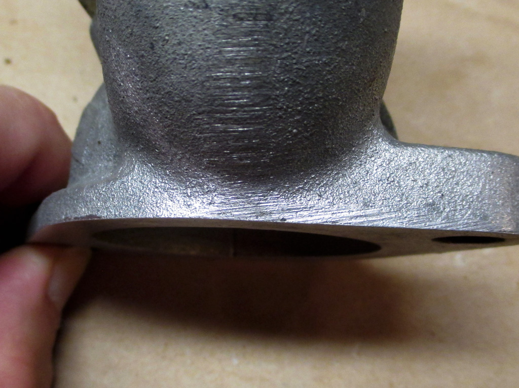
HERE TOO
The antifreeze must have weeped out of the gasket and gone up the front of the housing just enough to make it look like a crack. Not only that, but there was no pressure in the system either as I haven't run the van in weeks. Too weird.
A quick trip to the autoparts store netted me a new thermostat gasket and some copper gasket adhesive (best stuff ever for gaskets), and I torqued the housing down to 30 ft. pounds, as recommended in my repair manual. With that little adventure behind me I could move on to other things.
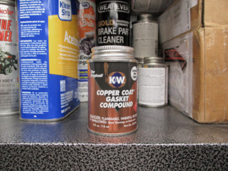
GOOD STUFF
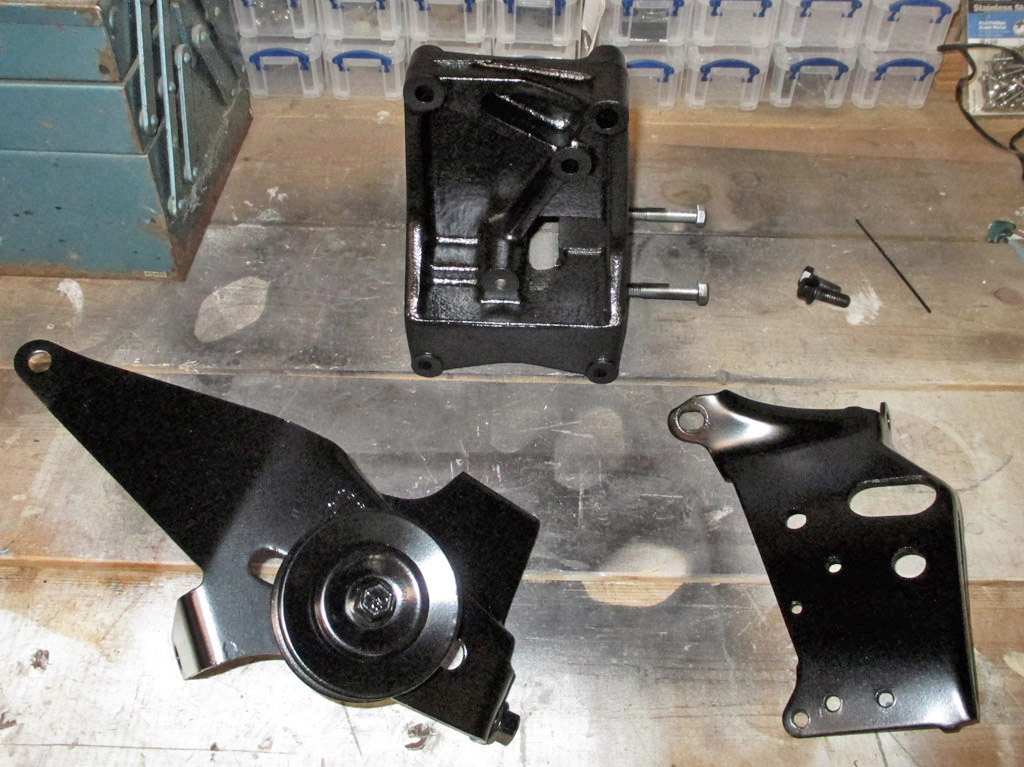
BRACKETS
Since my Rock Auto shipment hasn't arrived yet, I busied myself with lightly sanding the brackets, wiping them down with alcohol and shooting them with VHT semi-gloss black paint. I debated doing this for awhile, but finally decided what the hell and went for it. The results weren't half bad.
As soon as I unpacked my shipment from Rock Auto, I noticed a big difference between the old compressor and the new compressor. One of the reasons for choosing Rock Auto in the first place was not having bottomless pockets where cash is concerned. The compressor listed on their website for my application was #57096 detailed as: "A6 Compressor with 5.12 Dia. Pulley." However... in measuring what they sent me, I came up with 4 and 7/16ths inches. Quite obviously this is the wrong part for my application. Time to call customer service.
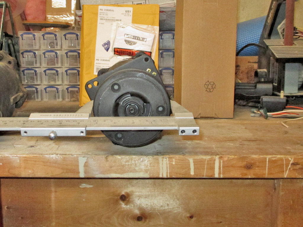
NEW ACROSS CENTER
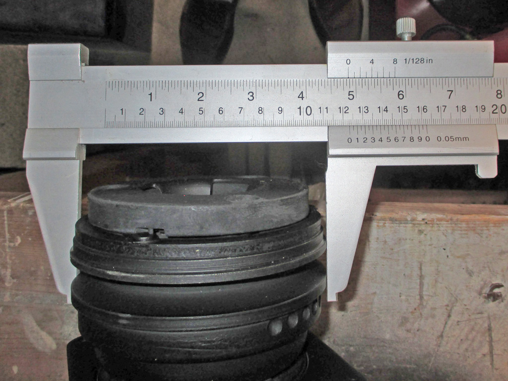
NEW PULLEY SIZE
This was my first time ordering parts from Rock Auto. The primary motivation was cost. Rock Auto is very, very much a self-service operation. As long as you know this going in, no problem, but you will not find any sort of technical assistance whatsoever. Their first few phone options tell you where to find what you need on the website. Chances are if I'm calling you for assistance, I can't find the answer on the website! At any rate, I got a live person, explained the situation and he... you're going to love this... proceeded to read off the website the same thing I'd read myself several times. I quickly realized the folly of my actions, thanked the guy and hung up. I doped out the rather lengthy return instructions (the part I received was "mis-boxed") and printed my return label. Wrapped the box the compressor came in with brown post office mailing paper and went to FedEx. They don't want you to do that by the way, (the paper gets hung up on the conveyor belts), but they took it and that phase was complete.
Now then... Let's take a look at my somewhat worse for wear original compressor. I could tell there was a difference before I broke out my jumbo caliper, now it was time to see how big a difference there really was.
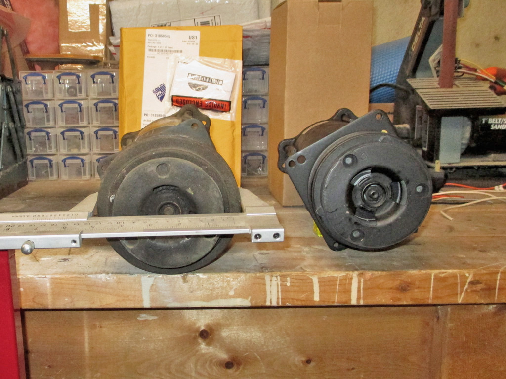
OLD MEASUREMENT
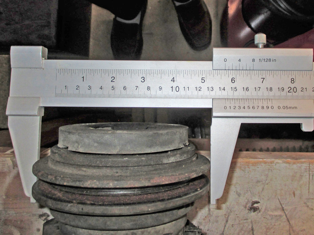
OLD PULLEY SIZE
According to my high-end measuring instruments, the original pulley was 5 and 5/8ths inches in diameter. I went back and forth a few times before I spotted the sticker on the new compressor. I needed a magnifying glass to read it but it clearly said #57099. Ah ha!
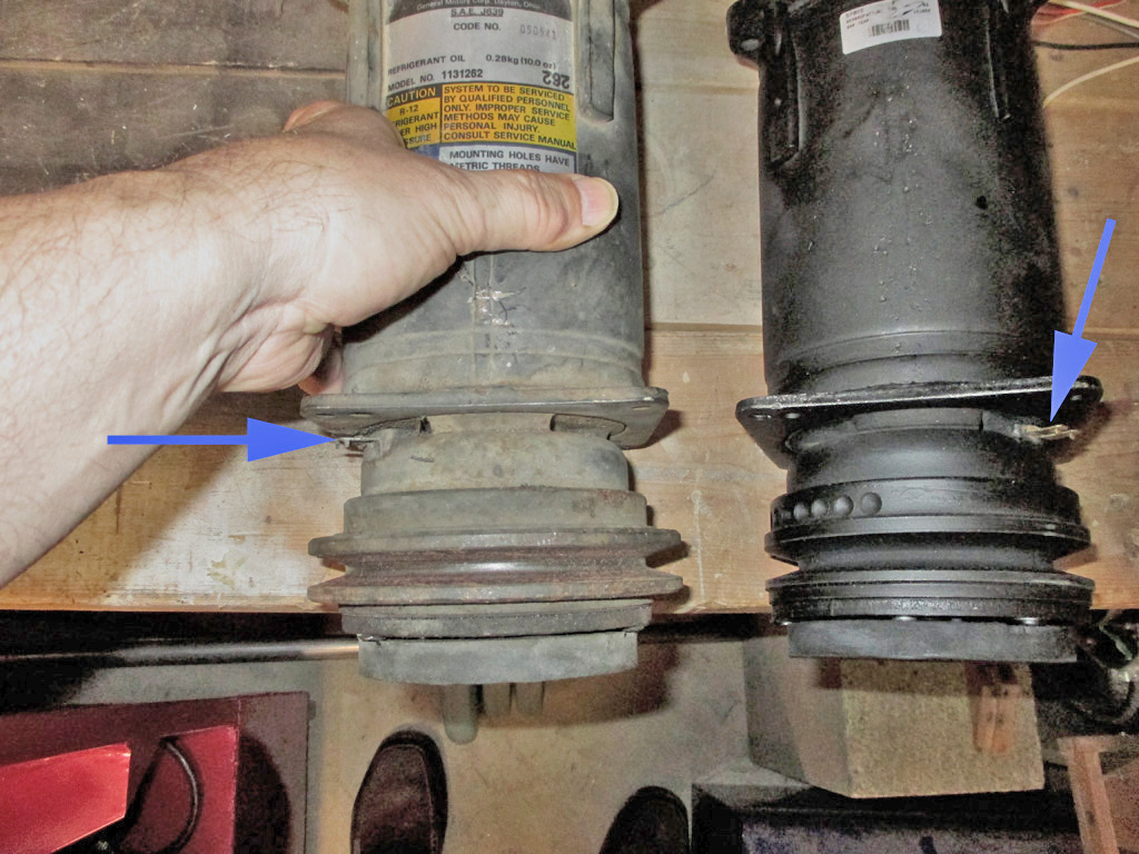
So, we've got a smaller pulley, a bogus part number and then (with both compressors lined up in the same position--oil pan down), the electrical connector for the compressor is about 45* from where it was on my original compressor. So, back it goes.
As I was doing my research online to get a feel for which brands of a/c parts had the best reputation (other than OEM), 4 Seasons was mentioned a few times as providing good quality parts. I'd read some online reviews from folks who do this for a living and they cited this brand as having fewer failures and fewer customer "bring backs" so I used this information when purchasing my parts.
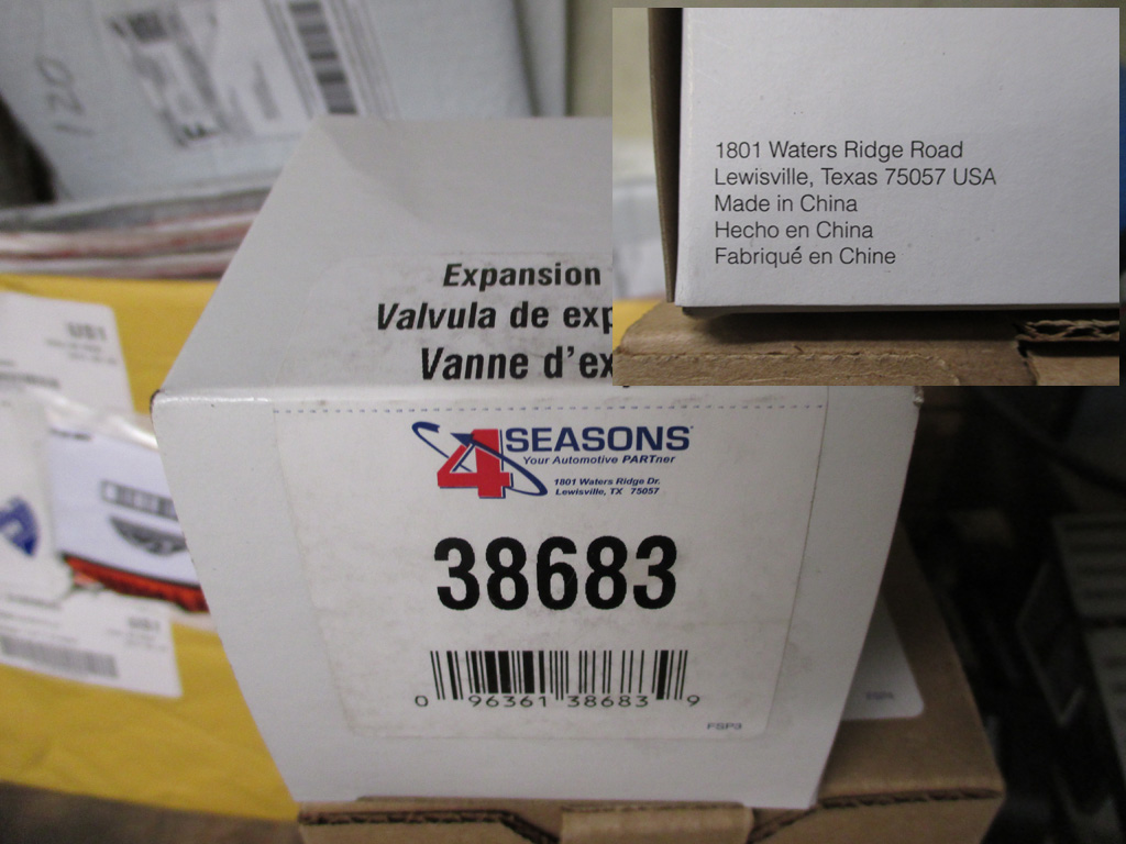
IMPORTED
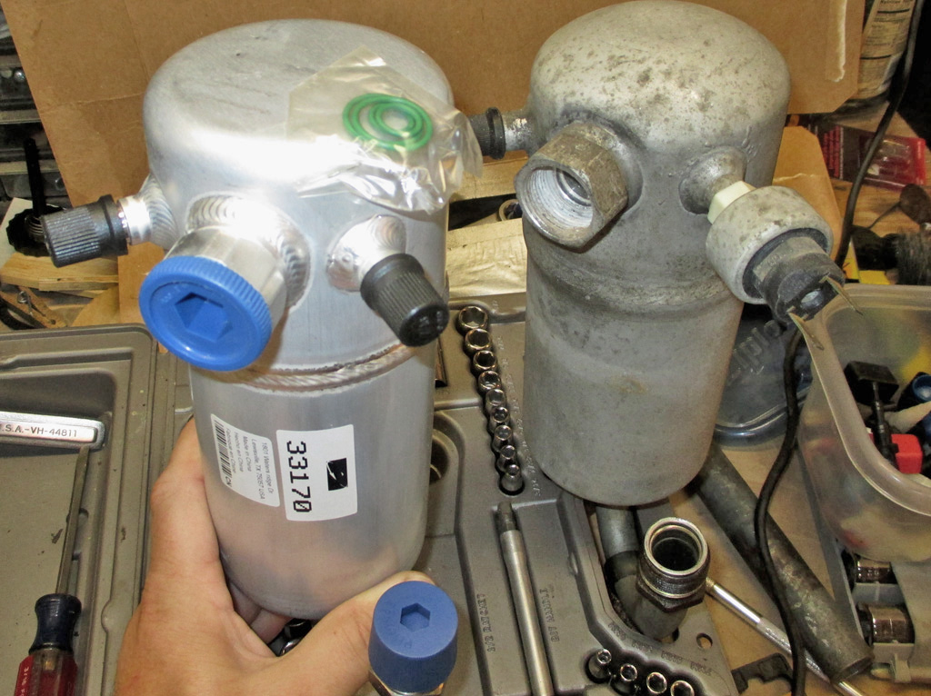
IMPORTED
I was kind of hoping for made in Canada or maybe Mexico. Nope, made in China, both the expansion valve and the accumulator/dryer. You get what you pay for I guess. I'd have been rather upset if I'd paid full freight for AC/Delco (OEM brand) parts, only to find they were made overseas. I've seen some OEM parts made in Mexico, but there's no telling these days.
While I'm At It...
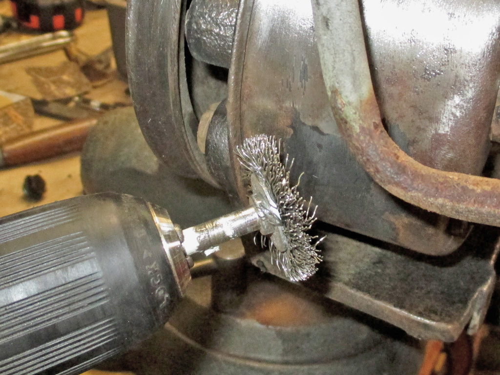
With the "mis-boxed" compressor on its way back to Rock Auto, I busied myself with another item needing attention. The high pressure hose on my power steering pump had been leaking since I bought the van. Since the bottom and back of the power steering fluid tank were rusty, I jumped in with both feet and yanked the whole shebang.
The only problem with respraying it is all the little nooks and crannies where hose connections and hardware mounts are located. This takes forever, wire-wheeling, sanding all the while trying to prevent the darned thing from leaking all over the place.
Several times I thought I'd completely drained the fluid tank... only to find a big mess later in the evening. With no other means to stop the leak, I cut the flared fitting off the old hose, threaded it into the fitting and capped off the metal tube. This stopped the leak... FINALLY!
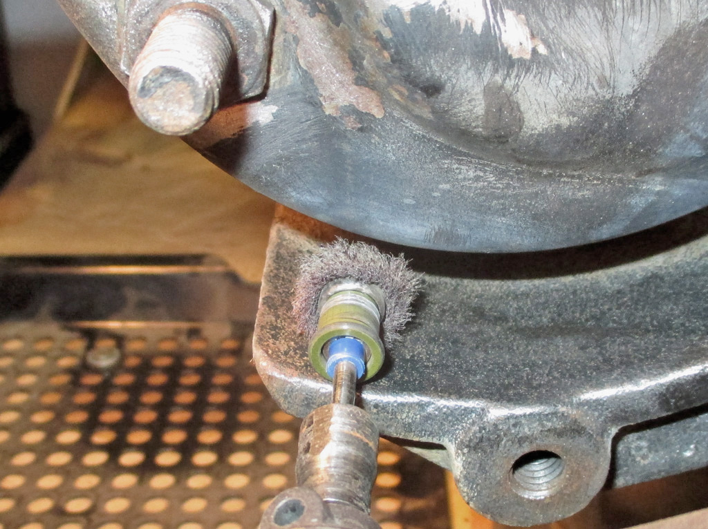
As with most projects I broke out all my toys including Mr. Dremel. I had a medium abrasive buffing wheel that wasn't doing anything constructive, so I pressed it into service getting into all the tight spots I couldn't reach any other way. The van had been sitting awhile before I bought it and the pulley had rust and mud dauber remnants where it had been exposed to the elements. Some 120 grit sandpaper made everything smooth again.
In some spots, I cut up a 120 grit self-adhesive sanding disk to the width of a putty knife so I could get into other tight spaces. A cone shaped abrasive attachment on the Dremel got into some other tight spots as well. In the end I figure I got rid of about 90% of the rust and it looks better to boot. My new hose should be at the local auto parts store in a couple of days.
So I spent several hours and many different approaches to remove as much rust as possible from my power steering pump assembly. A final wipe-down with 70% alcohol (wipe once, get a clean section of paper towel, repeat) and I was ready to paint.
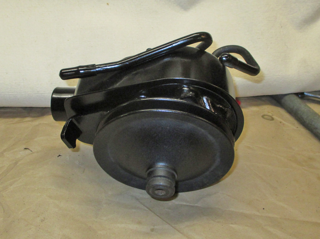
FRONT
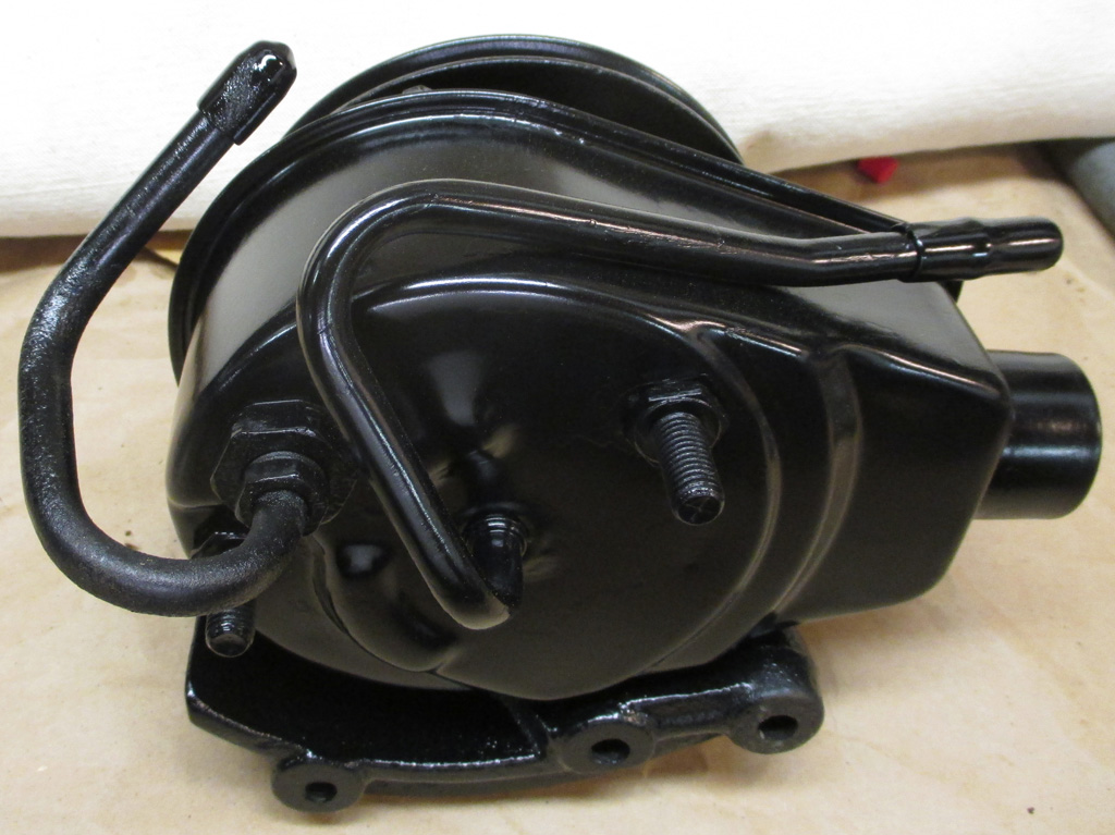
BACK
This time I used Dupli-Color's VHT series of semigloss black. Close enough to what the factory used for my purposes. Gave it two coats and called it done. If you look real close you can see where the new and old paint didn't quite feather out perfectly. But my allergies were killing me with the trifecta of sneezing coughing and the runny nose bit, so we're done here.
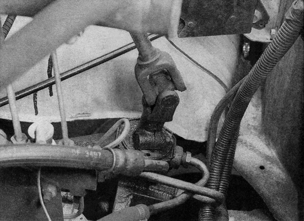
Time for a sidebar. I should've taken a picture of the hose locations before tearing everything apart. But I didn't. I figured, no problem I'll look it up in the shop manual I bought for just such an emergency. Only one flaw in that plan. Shop manual had nothing, nada, null set, zero information on hose location. An original factory published shop manual and all I could find were brackets... strike one.
I also happen to have a Chilton (strike two) and Haynes manual for my van. Fortunately, the Haynes manual came through with a rather grainy, grimy picture that I finally used to plumb the P/S pump to the steering box. Low pressure return in upper fitting, high pressure in the lower fitting. Once I get this baby fired up, I'll know whether or not I got it right. I scanned the picture into my computer, got rid of the nastiest specks and spots and saved it for future reference.
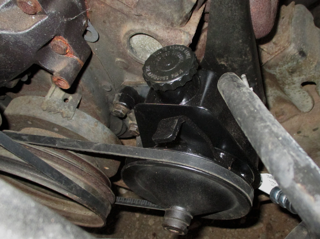
Nothing like fast shipments to keep you moving. I picked up the new high pressure hose from my local O'Reilly's, came home, bolted up the pump and set about installing the hoses. The return line is low pressure and I already had some 3/8 hose on hand, so that part was simple.
Next up, installation of the three (count 'em three) air conditioning brackets I refurbished earlier. I still need to come up with a parallel flow condenser for the new refrigerant. The special order one O'Reilly listed has to be ordered "blind" (don't know the cost up front, have to hope its the right one), so that solution is out the window.
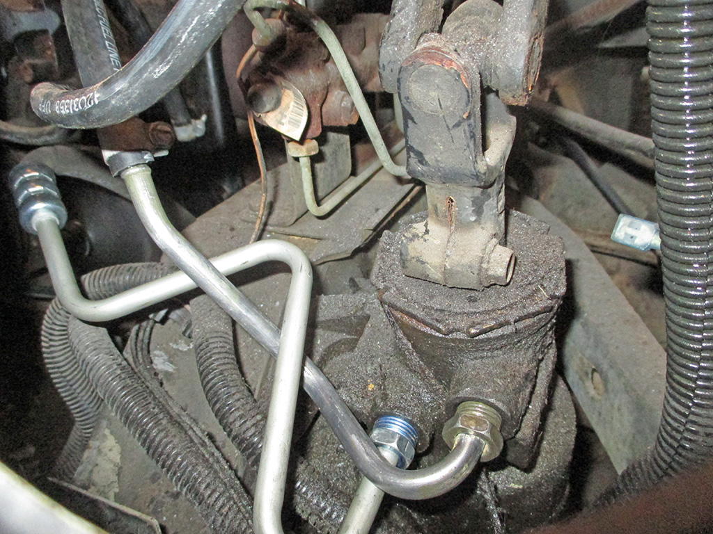
So, after all that work, the finished product. As; long as I was at it I figured what the hell and cleaned up the fittings for the low pressure hose as well. With all new hoses and freshly de-rusted tank and pulley, all systems are GO!
In the meantime, I received a confirmation that the right compressor (I sincerely hope) is on its way from good ole Rock Auto. Since they have zero tech help available, I went to my local O'Reilly's for a parallel flow condenser. They had one but it was a SPECIAL ORDER! Meaning I'd be ordering it blind - no price listed! Bet they move a lot of those... not. Sigh... back to the internet. I embarked on this quest in an attempt to have my van's A/C operational before the hazy-hot-humid stuff rolls in. I might just make it IF I can get all the parts rounded up, all the special orders ordered and all the leaks fixed. What a production!
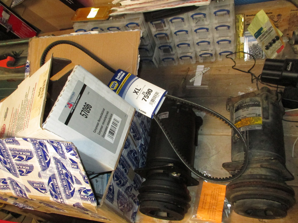
I'll say this much for Rock Auto, they ship things fast. Once I'd sent the wrong compressor back there was a new email in my inbox letting me know that the compressor had been shipped. A day or two later I came home to find yet another box sitting on my porch wrapped with roughly 700 linear feet of "Rock Auto" branded packing tape. The box itself looked like a 500 pound gorilla played hockey with it, but the inner box was undamaged.
This compressor has a 57096 sticker on it, which is the number recommended for my van (part of the kit for rear a/c), regardless of pulley size. The electrical connection is still on the opposite side than the original, but I may have enough slack in my harness to make it work.
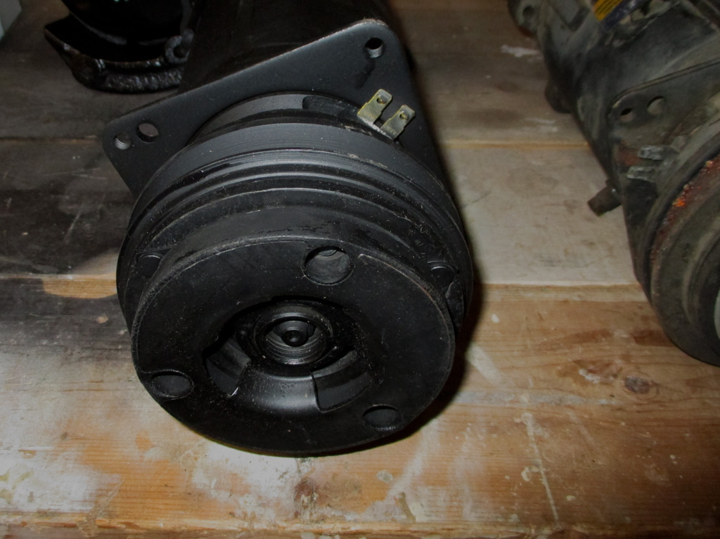
The difference between the pulleys isn't huge - the new one measures 5 1/16th inches in diameter, versus than the original 5 5/8th inch pulley. Is the difference going to matter? Am I simply overthinking the whole thing? Good questions.
So, now what? I can't keep returning things hoping to get the right part (assuming they actually have an exact replacement somewhere), and there is no one I can ask which compressor has which size pulley. With no other means at my disposal my plan now is to assemble my hodge-podge of parts and see what happens. You never know, I might get lucky.
I took a trip to our local Pull Your Part for some research. Equipped with a tape measure, I looked for a condenser that had the same kind of fitting set up as my original. I scoped out Fords and Dodges, but ultimately decided to stay within the GM family to make my life a little easier.
The 1993 version was the same fin/tube design as my van. GM changed condenser designs in mid 1994. The 2000 and newer Chevys have the same design as my Silverado with completely different fittings, so that's out. I'll need one from a 1996-99 pickup or suburban which looks to me the best match.
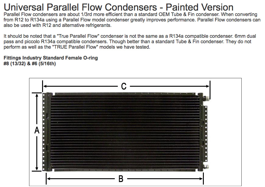
Following my excursion into the local boneyard, I came to a realization. If I'm going to upgrade my van to a modern 134-A system, I need to order the right parts. The more I researched this, the more obvious it became that I needed a new universal condenser, (the tight bends in used units hardly ever get cleaned out all the way), based on the largest that would fit my application.
I found a company called AC Kits (dot com) out of Arizona, which I'd discovered doing my research for this project. They sponsor the Automotive Air Conditioning Information Forum, which I found through the chevytalk.org website. That's how I came to find myself at the bottom of this particular rabbit hole. If I can get this wild conglomeration of parts to work in harmony and provide me with a fully functional a/c system, it will be a major victory.
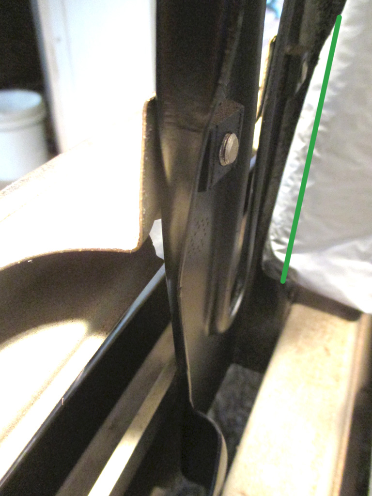
The bottom rail of the condenser was rubbing against the front support bracket. I was "in the zone" so I don't have any action shots. I took this shot and doctored it in PhotoChop to explain how much of the bracket got cut away. The green line denotes the original angle of the bracket. I used shorter bolts too, the factory bolts were an inch longer (needlessly) and almost touched the condenser.
This process really ate up the clock. Trim the bracket, CAREFULLY lower the condenser into position... nope need to trim off a little bit more. Once I thought I had sufficient clearance, I ground off all the sharp edges and shot it with some Rust Oleum satin black paint for protection. Shot the radiator supports while I was at it, so they won't be seen behind the new grille I've got sitting on a shelf.
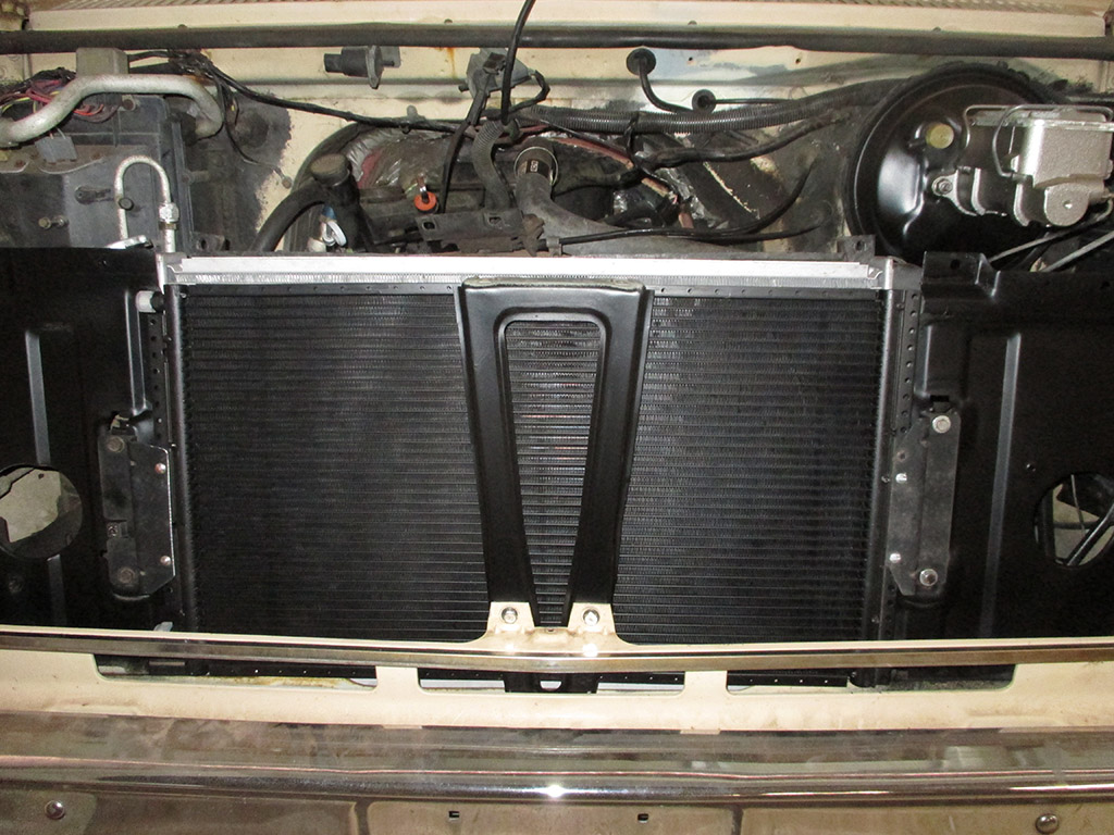
I lost count of how many test-fittings it took to get to this point but time wise it took me about six hours total. I kept the protective cardboard attached until I got to this point. I wanted to utilize the factory brackets since they seem to be quite sturdy. I used the driver's side as it was, the passenger side I had to trim about a half inch off and drill new holes to mount the new condenser. I used my angle grinder and it took me some time to cut through the bracket, so they must've used some really good steel for these at the factory.
Problems: The driver's side of the condenser is still sitting way too close to the front valance panel for comfort. Attempt number one saw me pulling the captive nut and bolts and using smaller bolts and washers to mount this driver's side. This only gave me a tiny increase in upward movement, but still not enough to give the unit the clearance I feel it should have. To add insult to injury, the secondary hood latch hits the top of the condenser. Back to the old drawing board.
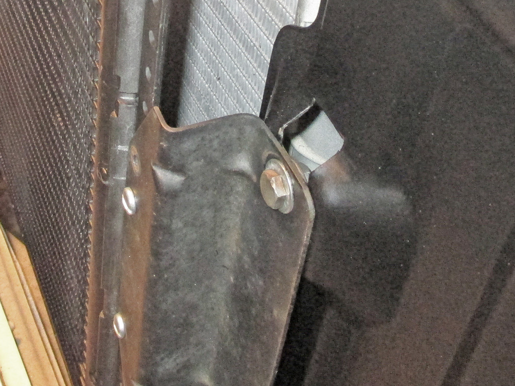
One nice thing about stepping back from a project like this and coming back to it later is you sometimes see new solutions to certain problems. The factory brackets mount to two extrusions in the radiator support panels and are also designed to hold the condenser forward. This new condenser is about half the thickness of the factory original, so I need to start modifyin'.
If I whip up a couple of flat brackets it will effectively move the condenser closer to the radiator by roughly an inch. My hope is that this will be enough to clear the secondary hood latch, which is my big concern at this point. Moving the condenser in this manner will also move it away from the front valance panel, killing two birds with one stone. Turns out I didn't really need to trim that front support brace after all. Oh well.
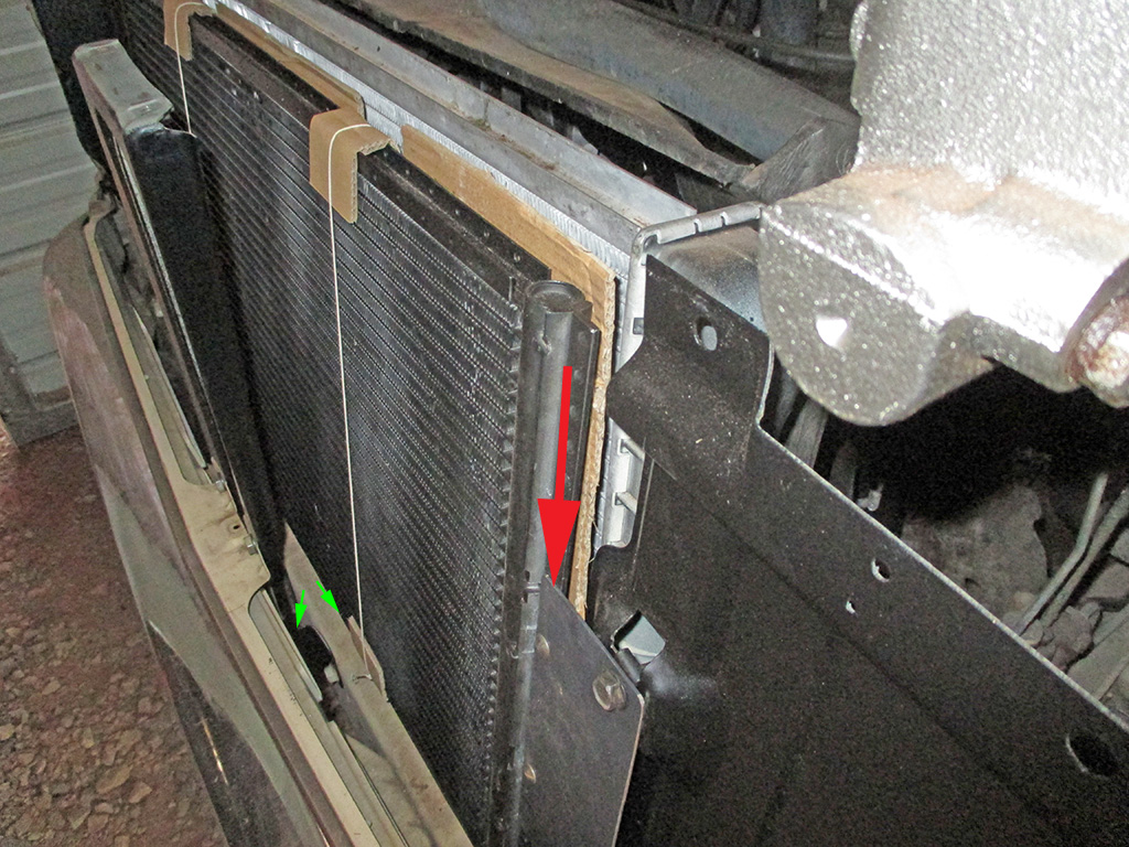
Here's a prime example of why I don't do this for a living. I'd probably starve to death! I was so determined to use the stock brackets, that I didn't see other solutions that were staring me in the face. I didn't need to trim the front support. By simply changing the S-shaped originals for the flat ones (red arrow), I gained about 1.5 inches of clearance (green arrows).
One simple change and all my clearance issues are solved. I still have to pull the condenser one last time, paint the edges of the brackets I fabbed up (corrosion protection) then I'll be ready for the final install. I'll still need to drill an opening for the top refrigerant line, but just getting the damned thing mounted properly took me most of 2 weekends... more or less. Ridiculous.
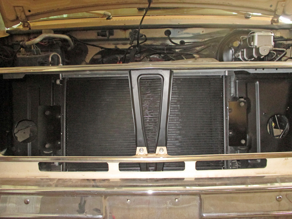
So here we are. Once again. I tied the shipping cardboard back onto the unit to protect it while I fabricated new steel mounts for the condenser. I removed it after the dozen or so test-fits it took to arrive at this point. Maybe now I can finish installing the new compressor and take the thing to a hose-fabrication shop.
On a positive note, whenever this unit requires replacement, (far, far into the future I sincerely hope) another universal condenser should be much easier to swap in now that all the fabrication work has been done.
Bodywork & Paint
Overhead Skylights
March 2013
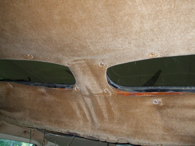
These two windows are the source of the water infiltration that has obviously been ongoing for quite some time. I base this assesment on the gobs of sealant used on both the outside of the rubber gaskets as well as the inside in a valiant effort to stem the tides of rainwater. Realizing that even re-gasketing these would probably only be a stop-gap measure, I am opting instead for a more permanent solution.
I was humming along, carefully prying off the upholstered buttons that cover the screw heads and removing the screws when it suddenly hit me. We've got skylights whose weathertight qualities are critical to prevent water damage and someone has the bright idea to run a bunch of screws into the gaskets. That's just marvelous. Must've been a Friday... or a Monday.
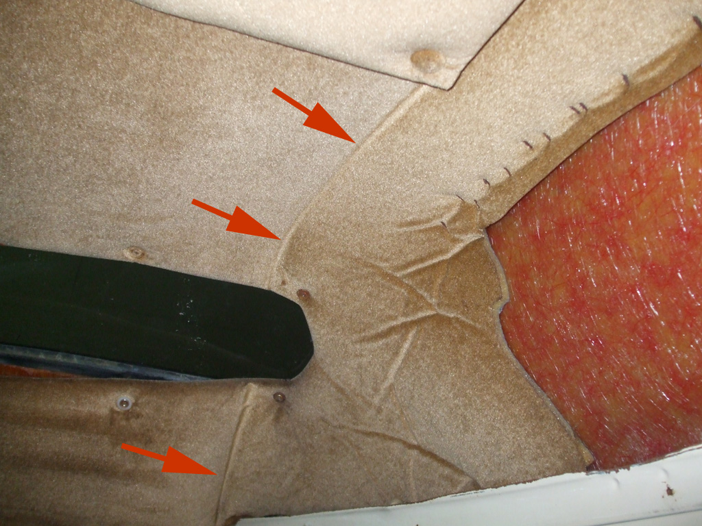
Not only do the side panels overlap the skylight panel, but the amount of extra material hiding behind the side panel was simply staggering. In fact, if it weren't for the various overlapping upholstered panels, I may have already begun my repairs. Most of my effort at this point has been careful disassembly to get down to the actual window seals whose failure has caused this headache.
It still blows my mind that screws had been run into these gaskets to anchor the upholstered panel that finishes off this area! Oh... the red arrows? They indicate where the side panel overlapped the front roof panel.
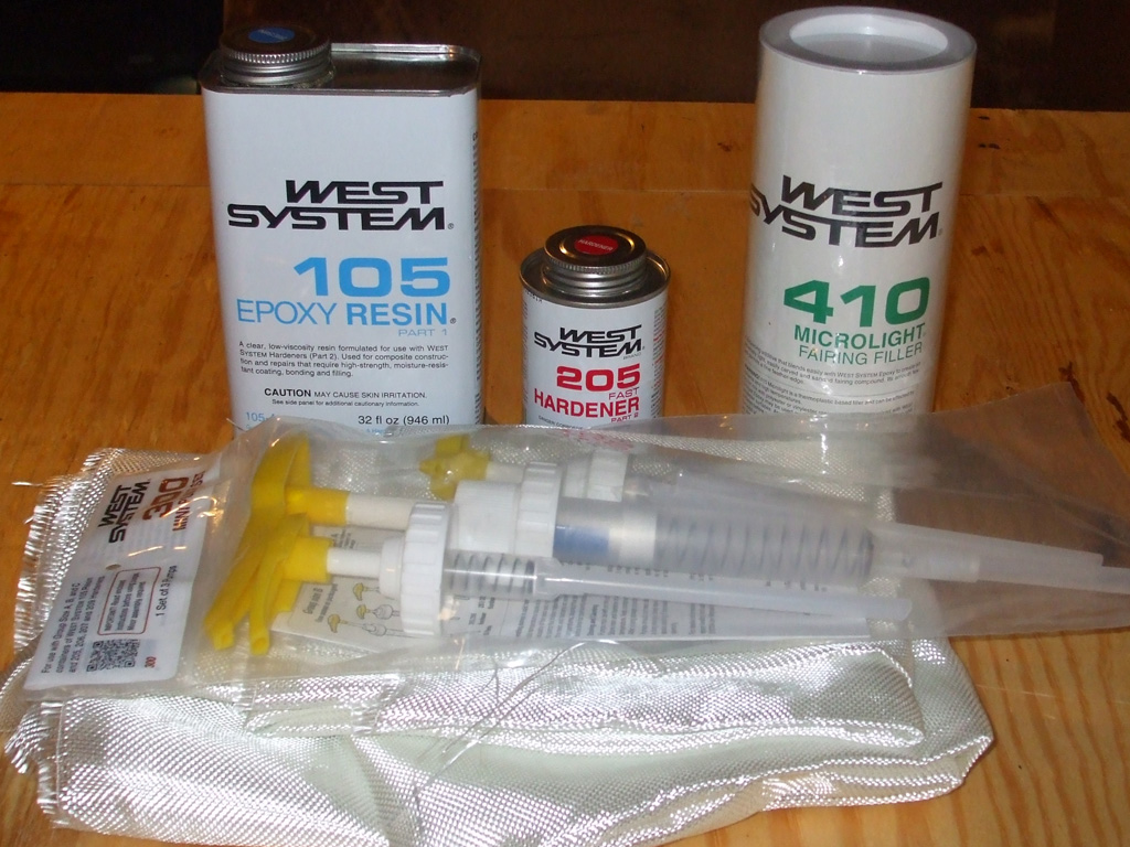
My solution... The Ultimate Solution! Fill in those blasted window openings with fiberglass cloth, luan plywood (as core support material) and epoxy filler. I spoke with a knowledgable boat builder at West Marine about the problems I was having and explained the material I was working with and the holes I would need to repair. I figured if boat construction methods are strong (not to mention water-tight) enough to be used as a boat, then it would be just the ticket for this little project.
First, I pried out the center rib that keeps the rubber gasket spread within the hole in the roof. Then a little coaxing with a flat blade screwdriver and presto! The window was out. Window? A thin piece of plexiglass held in place by a rubber gasket! A gasket that had definately seen much better days.
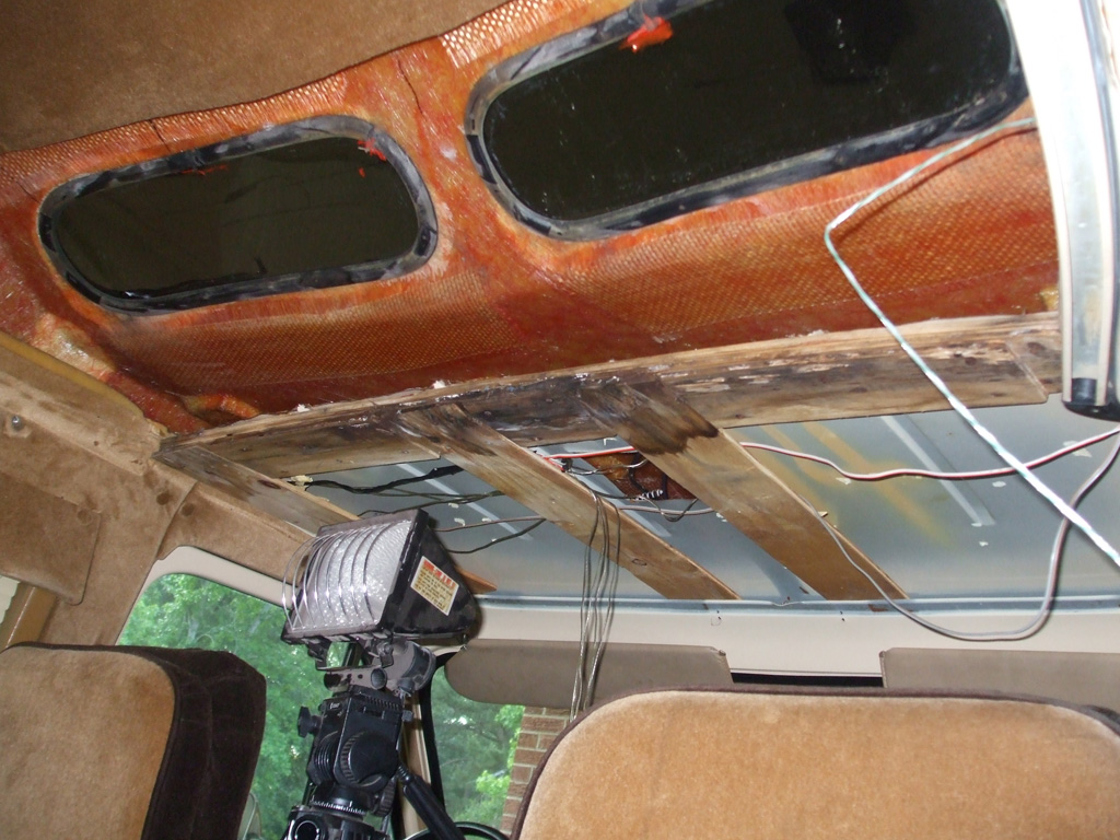
After weeks of procrastination, I finally got a nice rainy dreary Sunday and decided to put it to good use. I removed the side panel from the driver's side of the van and was able to trim back all the overhead headliner that was in the way of working on the skylight windows. Water damaged luan plywood, headliner material... I grabbed my trusty tin snips (think scissors on steroids) and started hacking.
The next step will be to protect as much of the interior as possible because sanding the inside of the fiberglass roof is going to create the mother of all messes. I have to use some 40 grit sanding disks to rough up the inner surface for maximum adhesive compatibility. Then I have to wipe the area down with Acetone and then I can begin using the epoxy and fiberglass cloth that I bought about a month ago. What can I say... slow and steady wins the race.
Battery Box Rebuild
While I'm At It...
April 2013... this is a classic example of the "snowball effect." I began my day with a certain goal in mind, that being removal of the radiator for a professional flush. In order to drain the radiator, I needed to move the battery cables, so I thought "may as well get the battery out of the way and free up some space to work in. Well... once I saw the condition of the battery tray, I could hear the snowball coming... "It's huge... everybody run!
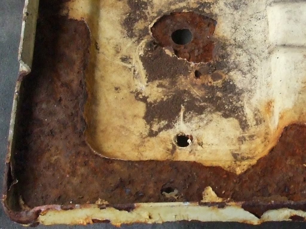
TOP
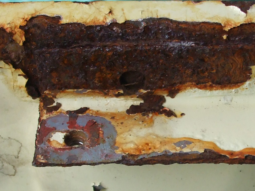
BOTTOM
At some point in its history, my van was involved in a front-end collision (I can see evidence of frame rail straightening underneath), and my theory is the battery ruptured. The evidence to support this theory can be found in massive rust damage to the battery tray, the support brace it was bolted to, the inner fender well and the inside and bottom of the radiator support. As I'm finding out, vans are not as well supported by the aftermarket as other vehicles. Amazingly enough, I actually did find a replacement battery tray, albeit without the opposing side brace. The problem? I wasn't quite ready to shell out $85 bucks for that privilege. The alternative... ya fix whatcha got.
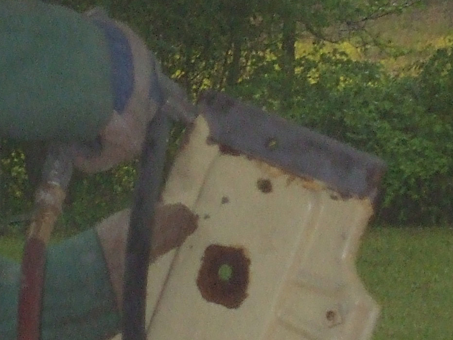
For a job of this magnitude, wire wheels and sanding disks can't reach into all the nooks and crannies the corrosion has left in the surface of the steel. That means only one thing... it's time to suit up and break out the sand blasting equipment.
Never a decision made lightly (the sand is insidious, getting into everything), blasting the steel seemed the best way to prep these pieces for paint. A couple of coats of epoxy primer and a couple coats of urethane top coat and I'll be back in business. By the end of this session, I had sand in my sneakers, stuck to my sweaty arms, down my pants pockets... hell I even had grit between my teeth when I closed my mouth! Sand blasting canister? Empties-ville!
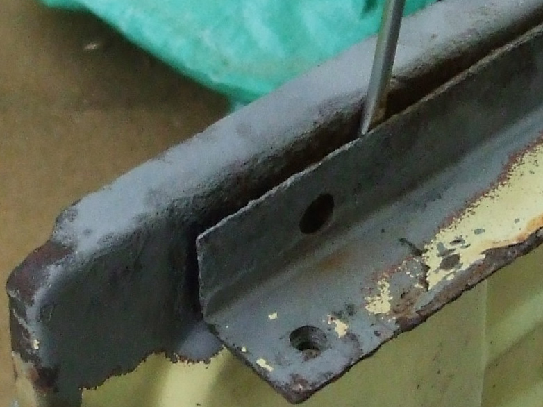
After the first couple of passes with the sand blaster, I noticed a thick buildup of corroded metal between the battery tray and the support bracket. I used a screwdriver to pry the two pieces apart, then used a putty knife to chisel the thick flakes of rust out from between both pieces of steel.
I had also used a screwdriver to break loose the large flakes of rust laying in the bottom of the battery tray, but this situation required a tag-team effort. Once I had as much of the area cleaned out as possible, I returned to sandblasting.
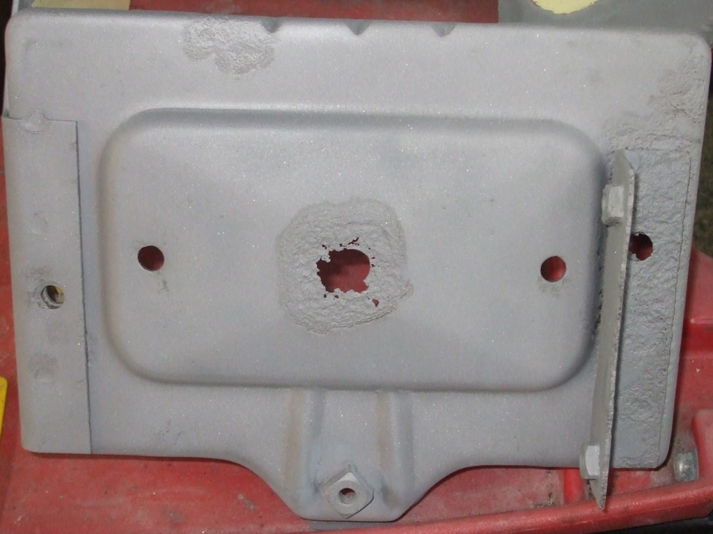
After several hours of blasting (including sweeping up the spent sand and sifting the resulting reclaimed sand back into the blaster canister), here's where I ended up at the end of the day. The job may have gone quicker with fresh sand, but I used what I had on hand.
I wound up with both pieces being ready for the next step (epoxy primer, etc), by days end. It was dirty and time consuming, but hopefully I'll be able to get a few more years out of these refurbished parts.
After viewing the results of my labors, I did have one other thought. If I was really anal about this, I could (posessing a mig welder and a smattering of knowledge/experience), replace the damaged steel with new steel of the same gauge, making a more permanent longer lasting repair. Just not sure if I want to go that far or not. Some of the steel I'm left with is little more than mettalic lace, so I'm pondering the alternatives.
Battery Tray in Primer
May 2013
After hibernating in a super-ziplock bag full of rice to remove any residual moisture (sandblasting while it rained probably not the best idea), it was time to prime these pieces. These may no longer be perfect visually, but I think there's still enough strength left to press them back into service after a thorough preparation and refurbishment. Since these parts aren't really seen all that much either, I'm opting for function over form at this juncture.
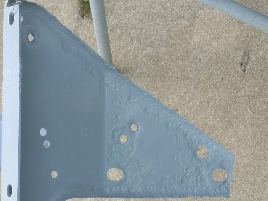
TRAY & SUPPORT
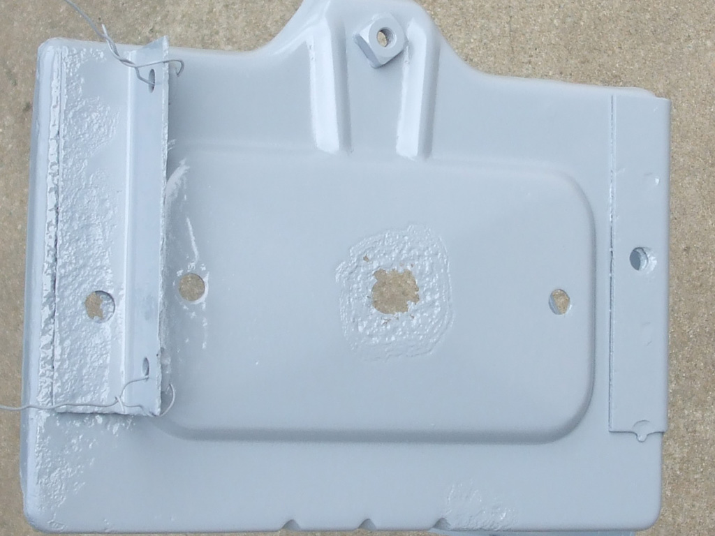
REVERSE ANGLE
At the end of the day, I'll certainly have more confidence in these parts than if I'd just ignored the problem and allowed the metal to deteriorate further. Ultimately I'll purchase a new battery tray bottom and weld it to the other supports so these parts will end up being totally restored at some future date. Although I may have slowed the rust down, we all know rust never sleeps, so future replacement rather than repair will someday be required.
Single Stage 2k Urethane for Battery Tray
June 2013
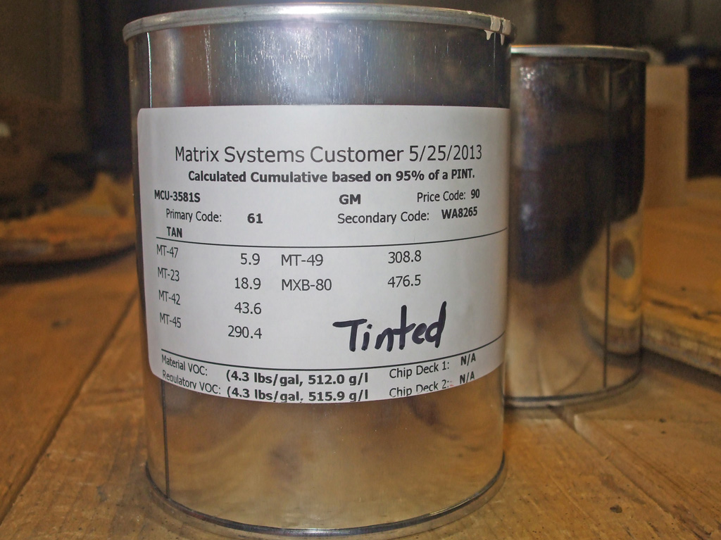
After several false starts (paint code close but required tinting... paintshop got busy and sidelined my order, only one person on Saturday... can you come back later?), my quest for paint became a comedy of errors. Three trips to the paint shop later I have a 1/2 pint of paint that matches the van pretty doggone close. Of course, the cute redhead mixing the paint blunted my frustration a bit and the third trip turned out to be the charm.
Since I'll be using this under the hood, I ordered a 2k single stage (no clearcoat) urethane. Who knows... I may find other places to use this batch as I do battle with the rust monster. The long, sheet metal cover that hides the sliding door hinge comes immediately to mind, since the inside of the cover (which only got overspray from the factory) has several rust spots emerging. My plan is to paint both the inside and outside of this panel to provide more corrosion resistance (I hope) than what the factory provided.
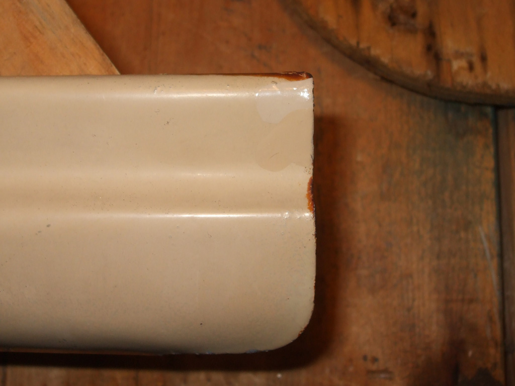
In order to match the paint as closely as possible, I took a digital snapshot of the underhood sticker that listed all the options the van was built with. I tried writing down what I thought was the proper code, but I goofed. When I showed the woman mixing the paint the photo of the sticker, she had the paint code deciphered in about 5 minutes. Naturally when I'm involved in a project, that tends to be just the tip of the iceberg as it would turn out to be in this case as well.
The paint code came up tan alright... but was way too light (probably due to age), to match the sample part the paint shop had requested for an accurate match. If you click through for the close up and look at the upper right corner of the part, you can see two sample dabs of paint (one pure, one tinted) that are very close. Since I'm painting the battery tray with this batch, It'll give me a good idea of how close a match the paint is without a mismatched panel staring me in the face every day.
After curing for nearly a month (while occupied elsewhere - see above), it was time to continue work on the battery tray. Since the primer had now cured sufficiently, it was necessary to scuff it so the surface would provide the best adhesion for the color coat to come. I used some 180 grit and light pressure (which amazingly enough evened out some of the low spots), to remove the gloss of the primer.
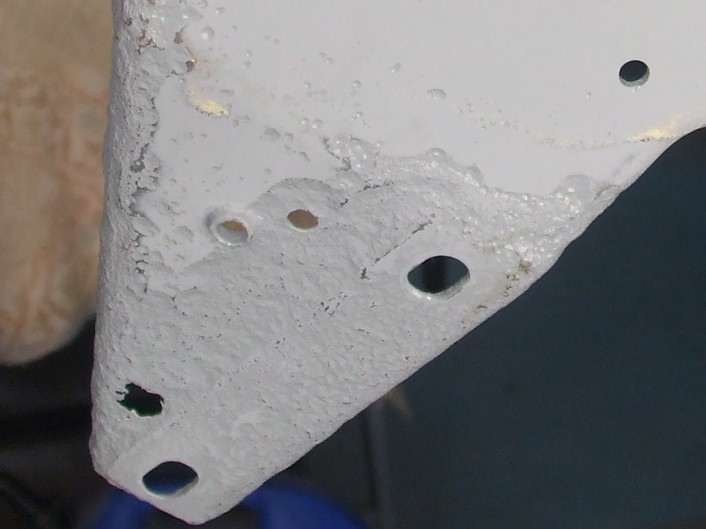
SUPPORT BLASTED
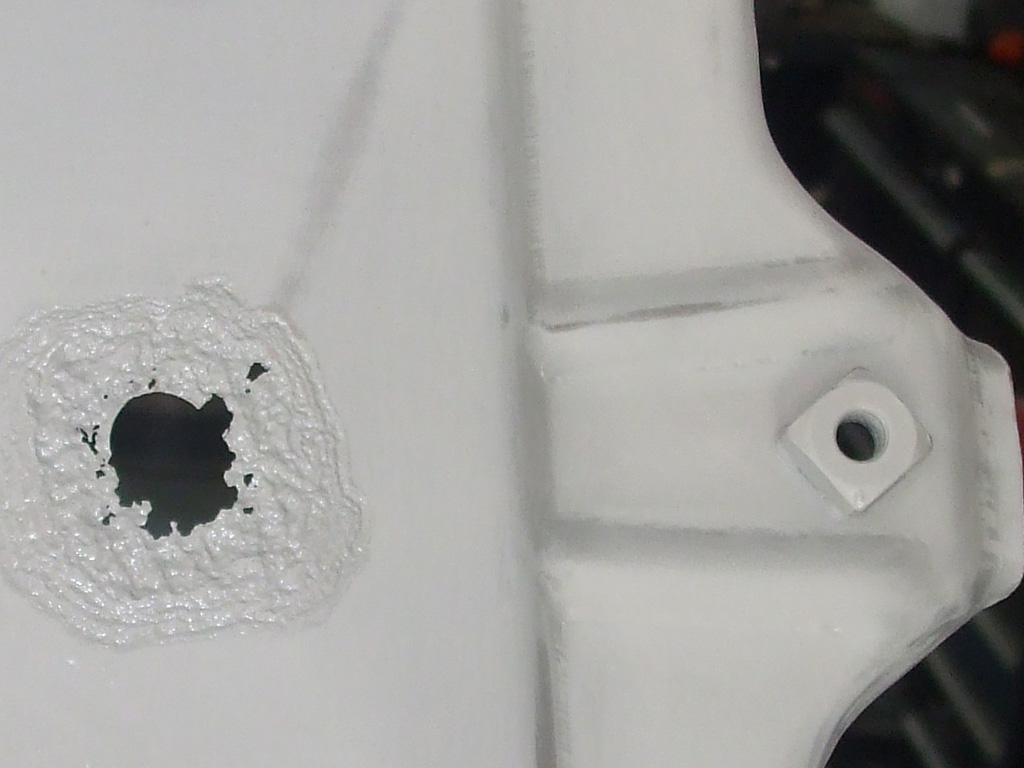
TRAY BLASTED
The only problem is... there's no way to sand into each and every pit in the steel, so I have to make do with just hitting the high spots and hoping the un-sanded recesses will not adversley affect the adhesion of the color coat. Ultimately though, it'll be in much better shape than it was and I should be able to use these parts for a few more years before replacement becomes absolutely necessary. It would have been nice if the P.O. had taken the time to rinse the battery acid off (even plain water would've been better than nothing), so the rust would not have been so severe.
The transformation upon adding color is pretty amazing. My theory is (since the battery tray and support both had yellow paint over red paint), that these parts were recycled from another van. I have reasons to believe this van was in a front end collision at some point in its checkered past and I'm now finding further evidence of this.
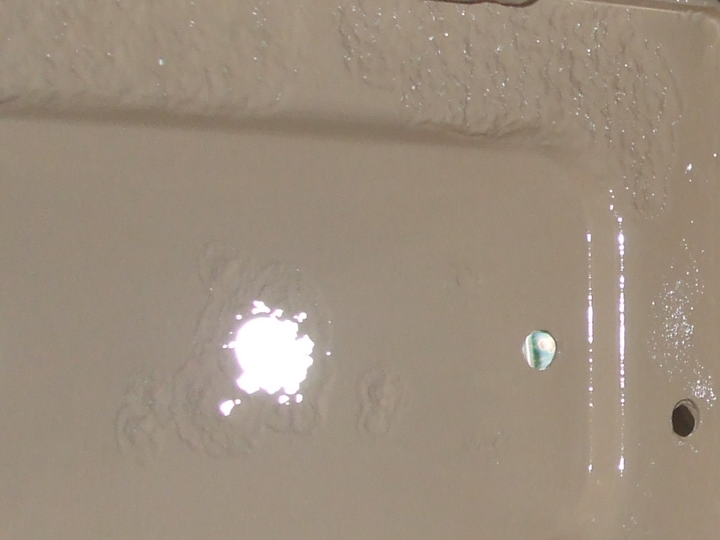
TOP
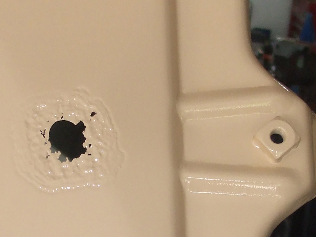
BOTTOM
Both lower front fender sections (below the belt stripe that was obviously used as a mask-off point), show signs of having been repainted at some point. It wasn't the greatest paint job known to man either, since several spots have begun to flake off (probably insufficient preparation) lending a rather scabby appearance to both. I don't really care, since the plan is to repaint this thing at some point, but it's amazing what just a little detective work can turn up.
As with the battery tray itself, the vertical support bracket also received a total refurbishment, at least to the extent of what is needed at this point. I could've gotten really anal and welded in new steel of sufficient thickness to totally restore these parts, but right now I want to get the van on the road and I still have the window replacement project waiting in the wings. I'm only hip deep in this because I removed the battery to replace the radiator and was faced with massive corrosion issues.
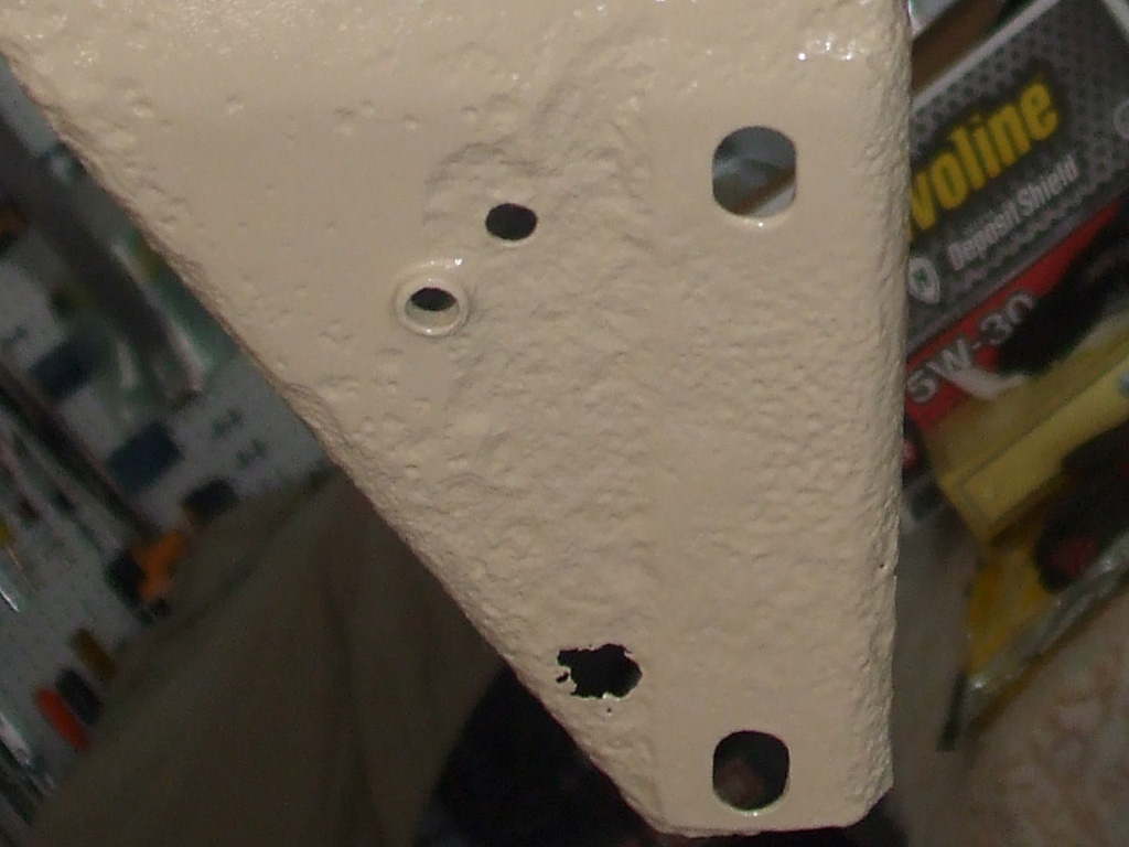
FRONT
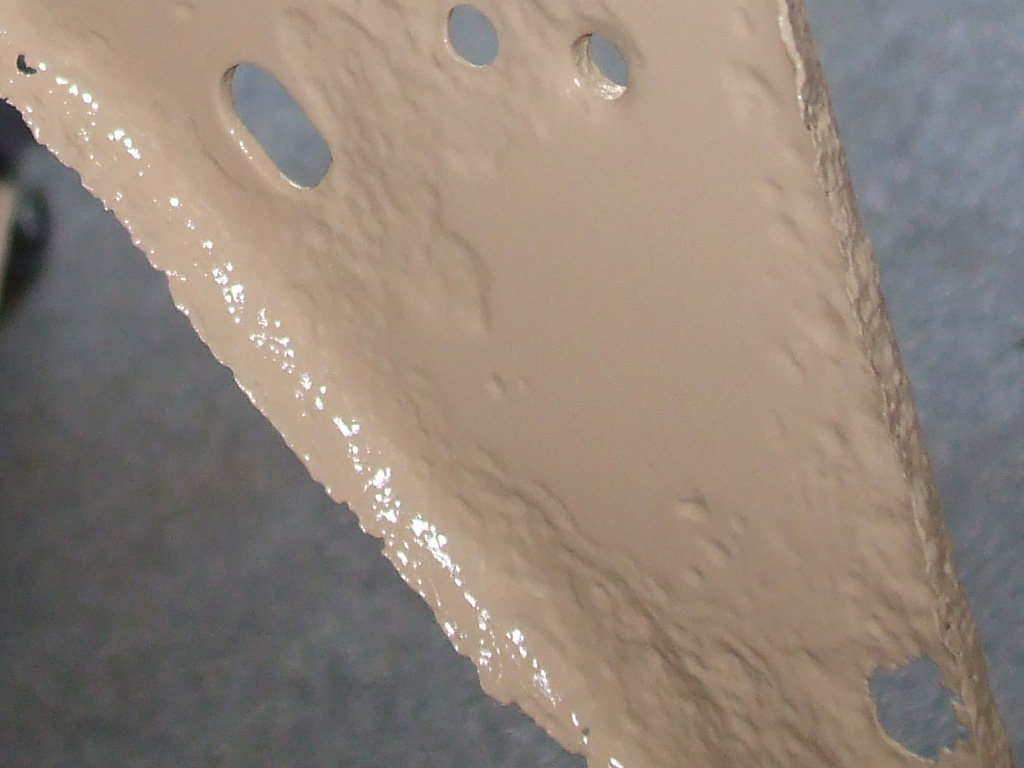
BACK
I hate rust! To the point where (as in this case) all forward momentum grinds to a halt while I repair the cancer I've uncovered. It would've needed doing at some point and I'd much rather be proactive in my repairs instead of waiting for the battery to fall out on the ground. I still have to patch the inner fender support before I can install these parts... another delay but when finished I can move on to other things.
Meanwhile, back on the van itself, I began the process of fixing all the corrosion caused by the battery other than just the battery tray. Where the vertical battery support bolted to the radiator support I need to sandblast and re-paint. Ditto the inner fender well where two separate spots look salvegable.
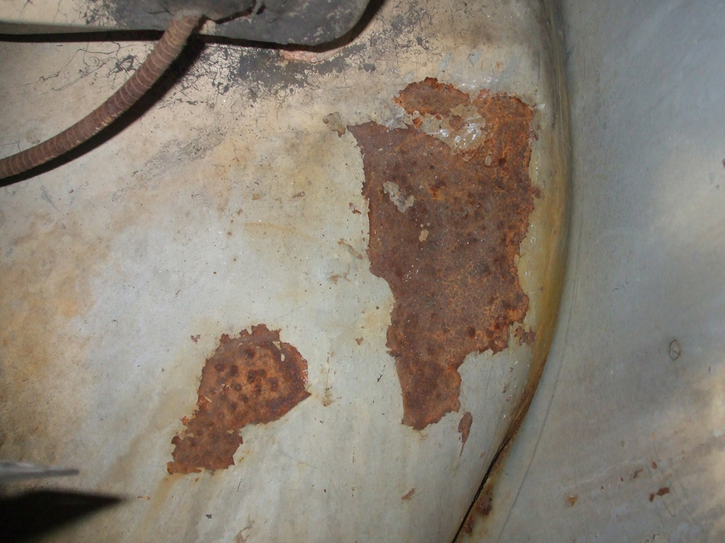
FENDER WELL
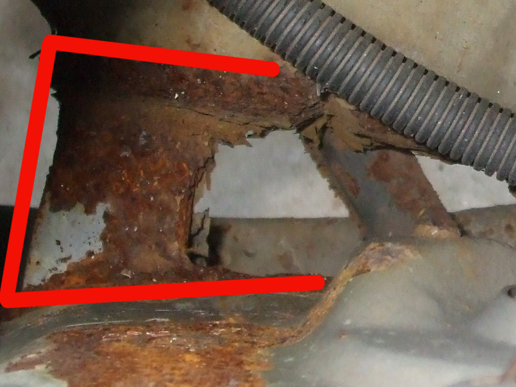
MISSING METAL
One L shaped portion of the radiator support will need to be fabricated and welded back in to replace what the rust has dissoved into complete nothingness! I'll also need to replace the bottom corner of the outer fender which is also missing. The cheapest fender I've found to date is 109 smackers, for the whole fender. I don't need the whole fender so my plan is to scrounge the local boneyard to see if (by some miracle considering my van's vintage), they have any I can pull a part from.
Back on the Roof
July 2013
So... after losing 3 months to other demands (upgrading the Caddy to DD status, house stuff), I'm finally able to begin the process of skylight removal. After getting advice on how to proceed from a boat builder where I purchased my repair materials and reading up on the process, I'm ready to jump right in.
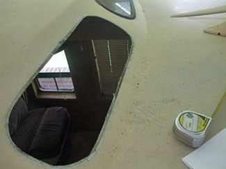
WINDOW OUT
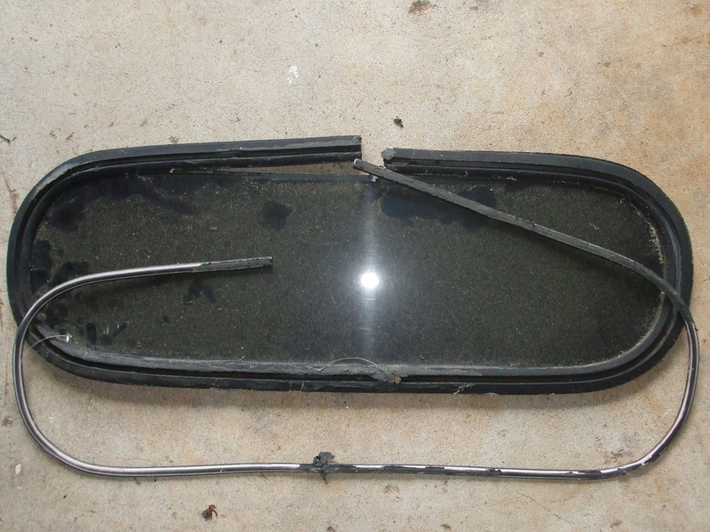
WINDOW?
This has got to be the loosest interpretation of a "window" that I've seen. A rubber gasket surrounds the plexiglass and fits into the opening in the fiberglass roof. Once in place the outside lip of said gasket, gets a tubular shaped plastic insert pressed into a groove provided for just this purpose. The gasket is NOT molded in one piece, requiring both ends be fused together, another failure point. In theory the plastic insert spreads the rubber and makes a weathertight seal. In practice it leaks like a torpedoed submarine.
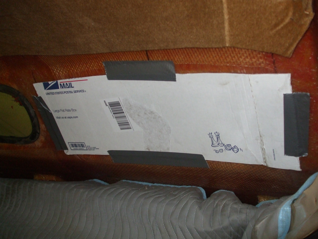
The first order of business was to protect the interior as best as I could from the massive dust storm on the horizon. I stuffed an old movers blanket in between the roof layers and side walls of the van to protect the cockpit area. Then I used a scrap of cardboard and some good old duct tape to prevent dust infiltration at the source.
I decided to prep the outside first, so when the time comes to adhere the fiberglass cloth to the inside of the roof, I won't tear into it when the time comes to work on the exterior of the roof. I am using some 2" 40 grit sanding disks to rough up the surface for maximum adhesive compatability. Then it's on to laying down a layer of epoxy, a layer of cloth... repeat as necessary to build up the thickness of the previous window openings back to stock levels. This should be interesting.
Since the interior is in pretty good shape, I made the supreme effort to protect the the middle (and to a lesser extent the rear), seats from the onslaught of dust to come. I had an old canvas drop cloth that I pressed into service as seen here. I'm hoping this will save me some clean up time (not to mention vacuum cleaner bags), when all is said and done.
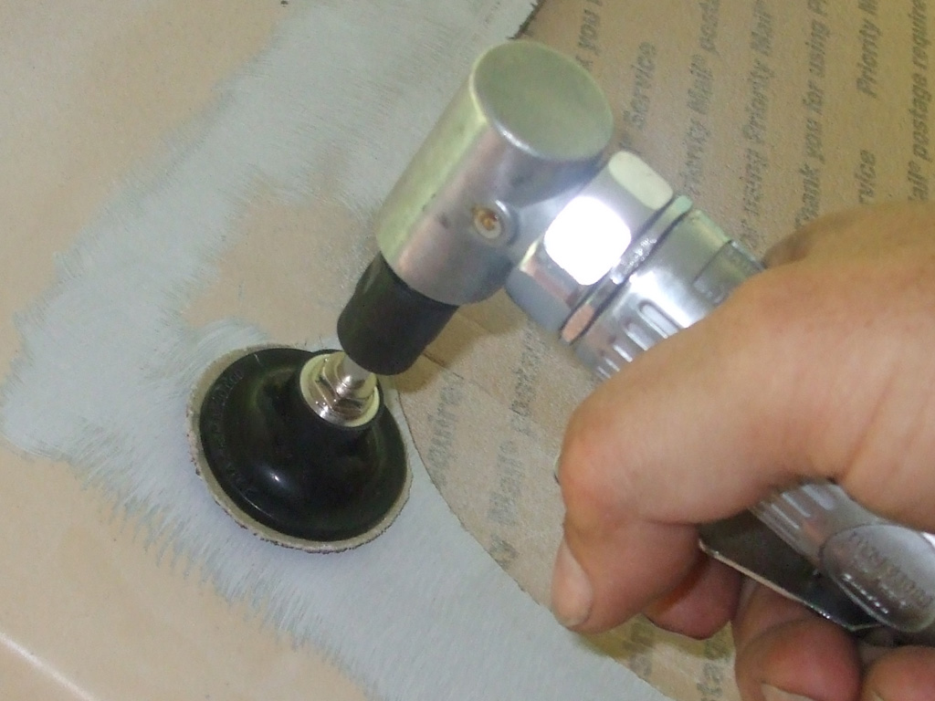
Now we can get down to business. According to various sources 1/8 fiberglass should be sanded back 3" from the opening to be repaired. This would put me onto the ridge line of the roof, so I settled on 2" instead.
The sanded back area is to give you enough room to build up several layers of fiberglass cloth and epoxy, each layer slightly smaller than the previous one. You let the epoxy resin cure until your fingernail still leaves a mark, then add another layer. If I miss that little window of opportunity, then I have to sand, wipe with acetone before adding another layer.
My goal is to have the roof appear to have been manufactured without any window openings whatsoever. This modification will dovetail nicely with my interior plans to upgrade the tiny B&W tv that was stupidly placed in the overhead console. A new (much larger) digital flatscreen unit will be installed in place of the windows, for center and rear passengers. I really don't see how the original setup worked. Between the tiny 6" screen positioned parallel to the floor (glare much?), not to mention a 3" speaker (located inside the console), it must've been a real viewing "experience" for the original owner.
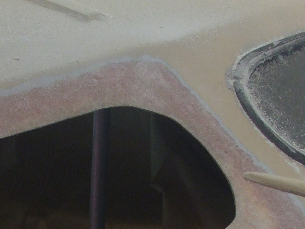
Having never attempted a project like this before, I consulted with a boat builder in the marine supply store where I purchased my fiberglass supplies. The original plan was to fill each opening with wood thinner than the fiberglass roof cut to the exact diameter of the hole in question. I would place the wood into the opening (held flush from the outside with short furring strips/screws), so I could lay a single layer of fiberglass cloth and resin over the patch from the inside.
Then I'd move to the outside (removing the screws holding the plywood to the furing strips) and layer decreasing diameters of cloth/resin to build up the depression I'd sanded into the outside surface. Thus the wood would be my core material sandwiched between the fiberglass cloth. That was plan A.

August 2013
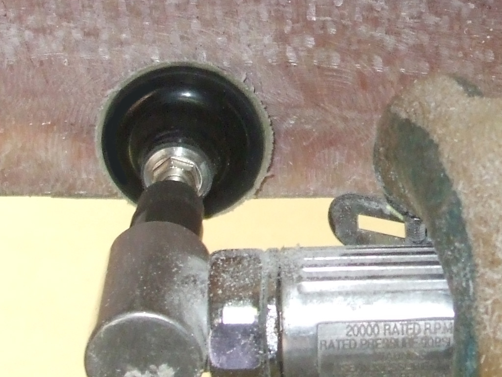
Now... where was I? Ah yes... when I discovered the plywood I'd purchased was THICKER THAN the fiberglass of the roof... well, my plan had to be modified. So I got to thinking... what if I mounted the wood on the inside of the fiberglass instead and then moved to the outside for the remainder of my repairs? The more I pondered my situation, the more my new approach seemed to provide the best solution. That's how my plan of attack evolved.
Once I decided upon 1/8 Luan plywood as my backing material the next issue became how to attach it to the inside of the fiberglass roof. I finally decided upon GORILLA GLUE! after reading that members of Vannin dot com have had good results with it attaching wood strips to steel in the construction of overhead consoles. The only downside to my use of the same glue is the irregular surface of the inside fiberglass roof. All adhesives work better with a roughened up surface to give the glue some "tooth" to bite into as opposed to a glass smooth surface.
To that end I grabbed my trusty die grinder, chucked up a 2" 36 grit disk and got busy. What a mess! Thank goodness I had the foresight to cover the seats with a drop cloth and a moving blanket before embarking on this spectacle of filth. 20 minutes worth of grinding and I had fiberglass dust (have I mentioned this stuff is itchy as hell?) everywhere.
Here then, are my two principle weapons of choice against the dastardly duo of leaking skylights. GORILLA GLUE! and some 1/8 luan plywood from the local Lowe's home improvement center. With the inside surface of the fiberglass roughened up and leveled out to my satisfaction, the moment of truth had finally arrived.
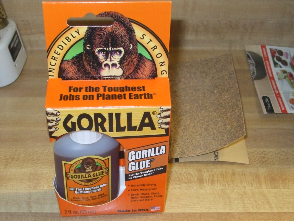
GORILLA GLUE
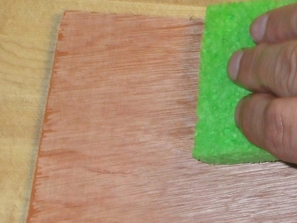
WET WOOD?
The instructions on the back of the package made for an interesting read. Evidently, GORILLA GLUE! uses moisture as part of the curing process and dampening one surface is recommended before applying said glue. Not only that, but the user is cautioned against over-application, since this stuff expands to 3-4 times its original mass during the curing process.
All I really need this stuff to do is hold the wood in place until I get the first layer of epoxy resin and cloth bonded to the outside surface. At that point if the glue lets go, it won't matter since it'll be epoxied in from the outside. Once I had the wood glued (and temporarily screwed) to the inside of the fiberglass top, I realized how the roof had become "bowed in" around each skylight, further validating my choice of repair methods.
If the screwdriver tip wasn't rolling just beyond my reach silently mocking my efforts, then I was knocking over the box of screws when setting down the drill, trying to pick up the sharp little bastards by hand which took great delight in piercing my fingertips. Not wanting to be left out, the wood tried to make a break for it several times and I found out the warning about Gorilla Glue staining your skin wasn't just an over-protectivce warning. Yessir, havin' some fun now ain't we boys?! In the end though, persistance paid off and I got my backer board installed as planned.
I'm back working on my van again and it sure does feel good. There's nothing quite as frustrating as knowing how to do something, having the tools necessary to do the job and to then have your plans derailed everytime you turn around by the stupidest crap.... Grrrrr.
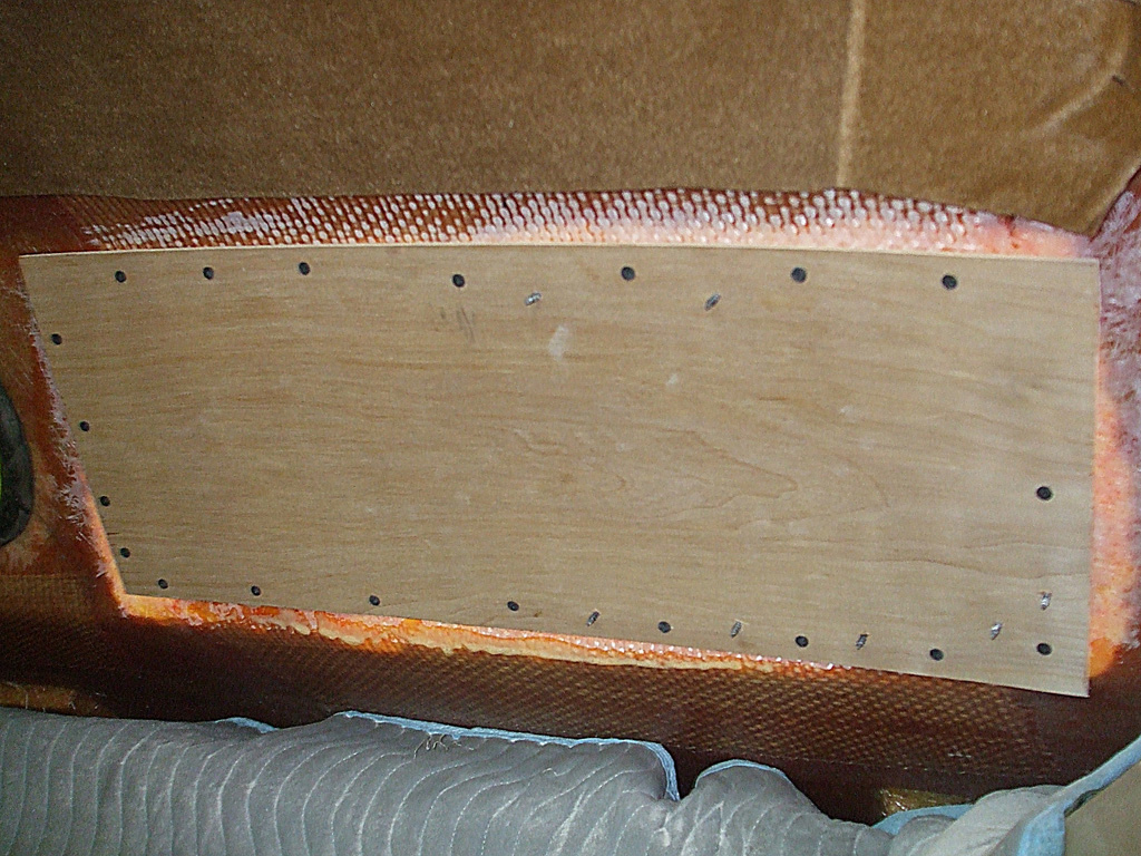
INSIDE
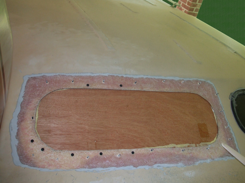
OUTSIDE
So, after moistening the wood with a sponge and laying down a nice thin bead of GORILLA GLUE! the juggling act could commence. I had my box of screws handy, drill bit, screwdriver bit and drill (with quick disconnect installed) all at the ready . . . and then the circus came to town.
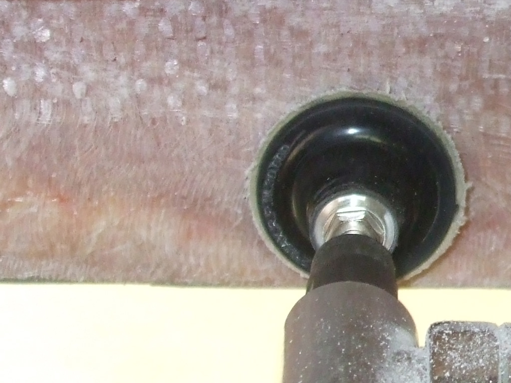
Flush with success following my efforts on the right side, I had no hesitation whatsoever about plunging headlong in on the left, even managing to break the "glass" of the left window in my haste to remove it. I did however change my approach just a tad.
Having discovered (on my previous efforts), that the fiberglass dust reacts rather badly when making contact with human skin, I decided upon a wardrobe upgrade since wearing a T-shirt and shorts (it was nearly 90* in the shade after all), obviously wasn't the smartest choice I've ever made.
Back when I replaced the attic insulation in our house (the notoriously itchy pink fiberglass material), I suited up, covering as much of myself as possible. Of course, I did that job in January when I didn't mind being covered up from head to toe. Turns out vehicle fiberglass sanding dust is every bit as much of a skin irritant as its insulation cousin used in housing construction.
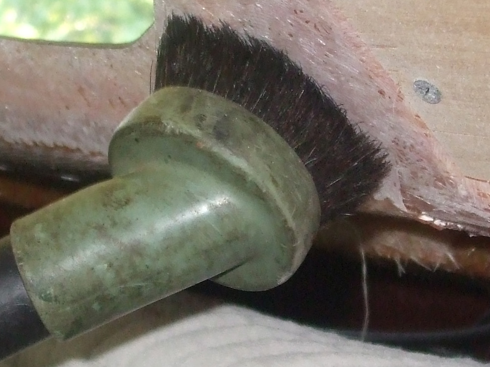
After my previous experience with the nasty nature of fiberglass dust, I threw caution to the wind and "de-gloved" one hand to more easily manipulate the shop vac controls.
Since the GORILLA GLUE! requires that one surface be moistened and have the glue applied to the same surface, I made sure that the freshly leveled and roughened surface was as clean as possible without resorting to the Acetone. I will reserve that approach for when I begin work on the outside of the roof. For this part of the process however, a quick cleanup with the shop vac will suffice.
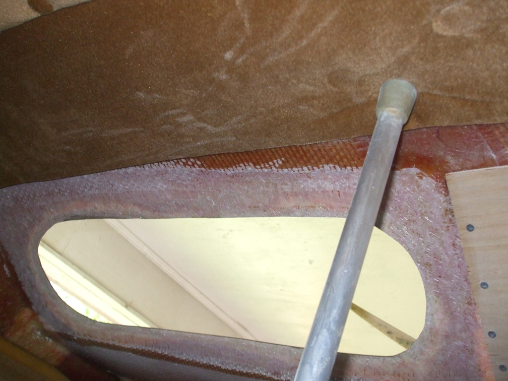
Here's a shot of the left side just before applying the plywood to the inside of the roof. The aluminum pole in the middle of everything is being used to support the headliner while I do my repair work. I'd tried using some gasket adhesive to hold it up and out of the way but it only held for about a day or two. I'll probably replace this section anyway but just wanted it up and out of the way while I worked.

Here's a perfect example of what NOT TO DO. It's not often my initial efforts at something eclipse follow-up efforts, but in this case it happened. I'm not sure why I decided to use a wavy glue pattern (although this was similar to paneling I've hung in the past) maybe it was late in the day and I was pushing to get this done. Yep, that's my story and I'm sticking to it.
It was around 7 in the evening, I was hot, tired, hungry... the dog needed to go out and was prancing around like a deranged lunatic and then my wife came home from work. It was a perfect storm of interruptions as my wife pointed out that the dog wanted his "out" (thank you Captain Obvious), while the cat began yowling while simultaneously trying to entwine himself between my feet. Yep, we're having some fun now!
In my first go-round, I laid down a nice straight line of adhesive, about one inch in from the outside edge, all around the dampened perimiter. It worked out much better than my follow-up effort seen here.
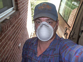
During my first attempt, I had on my eye glasses, gloves and a dust mask (but little else in the way of protection against the insidious fiberglass dust), and ended up with a ghastly case of the itchies later in the evening. I used compressed air, and the garden hose on my bare arms and legs, followed up by a nice long shower, all to no avail.
Should you be so foolish as to mimic my stupidity, know that there is a cure. If you're a guy though, you'll be paying a pretty stiff penalty. I took two strips of clear packing tape, roughly the length of my forearm and placed them adhesive side down, on my arm, overlapping each strip longitudinally. I pressed down firmly and then.... I pulled the tape off!
Thankfully my legs (oh so much hairier than my arms) did not require such drastic treatment. My fingers though protected (I thought) by gloves, required a more drastic approach. I took a strip of Duck Tape (roughly twice the length of one finger), and ran it down the inside of one finger and up the next, pressing down firmly as before. I then pulled the tape off and wiggled by fingers to see if they still irritated each other. I had to repeat this several times before the adhesive removed all the offending particles. The moral of this story is... protect as much skin surface as possible when working with ANY TYPE OF FIBERGLASS.
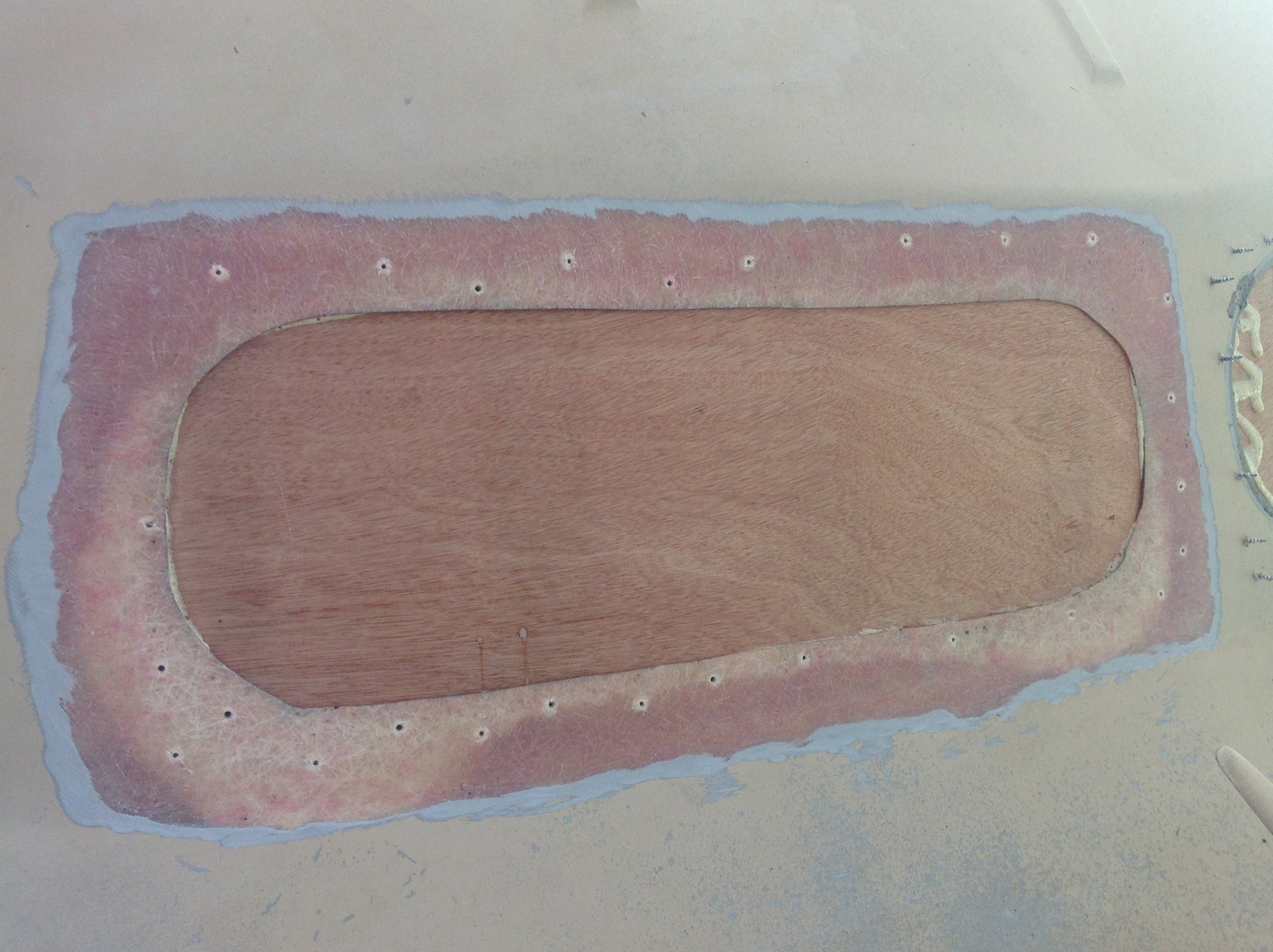
Sunday dawned bright and clear with forecasted highs in the mid-upper 80's. I was determined to get an early start and had things off to a rolicking good start by 9AM! Of course I got side-tracked several times, but I went with the flow and eventually zeroed in on my primary target.
First and foremost I decided to remove the moving blanket that had been protecting the cockpit area up front. I worked carefully, keeping all the itchy fiberglass dust contained as much as possible as I carefully removed the blanket. I threw it over the side wall of the carport and vaccuumed all the fiberglass dust off it, then folded it up for storage. The plastic floor runner was next only with this I simply hosed the dust off and left it to dry in the sun. I then gently pulled down the edge of the headliner I'd cut back and vaccuumed all the dust from up there so I wouldn't inadvertently disturb it and end up doused with dust.
Finally, I removed all the sheetrock screws that had been used to clamp my backer board in place while the glue cured. I could feel ripples in the outside surface, so I used my 'lectric drill (equipped with a 6" 40 grit disk), to flatten out the bevel in the hopes the epoxy would have a better sub-strata. I took great care to use the drill at low speed so the dust wouldn't fly all over the place. I also took care not to sand the fiberglass right down to the wood, per West Systems instructional videos I found on YouTube. I then vaccuumed up all the dust, gloved up and wiped the fiberglass down with Acetone as my final preparation.
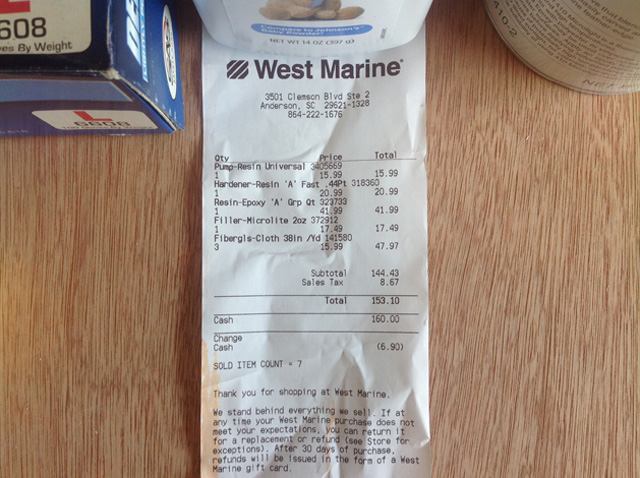
Part of my preparations (aside from gathering up all the materials I'd purchased a couple months ago) included trimming a piece of plywood to use as a work area atop my trusty service cart. I sure hope this West System stuff lives up to its hype, at close to $150.00 bucks in materials this stuff ain't exactly cheap!
Since I knew I'd be working with some nasty chemicals I broke out my nitrile gloves (some baby powder helps them slide on easier) and roll of blue paper towels. One thing I like to do is pick up my mixing dishes at thrift stores like Salvation Army or Miracle Hill. You can get 'em dirt cheap (none more than 50 cents apiece) and for purposes like mixing up epoxy they're great. When you're done just toss 'em in the trash and move on. The plastic mixing cups at the marine supply store were hideously expensive in comparison and wouldn't have worked any better than what I'm using here.
I had a bundle of craft sticks (which look suspiciously like medical tongue-depressors) left over from something, so I grabbed a handfull to use as mixing sticks. The only other thing remaining to be done is to trim the fiberglass cloth to the proper size and then mix up my first batch of epoxy. I like the way the West System uses their 1-to-1 ratio of resin to hardener. Three pumps of epoxy, then three pumps of hardener. Mix and apply. Sounds simple, so I hope it is simple in actual use, since I'll be up on a ladder for the next part.
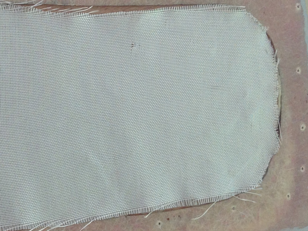
According to the West System video, you're supposed to go from the widest part of the patch and work your way down to the smallest when layering fiberglass cloth for a repair such as this.
However, other videos detailed the process the other way around, from smallest diameter first, working up to the largest diameter last. Now what? Upon recommendation from folks who've actually used this material, I decided to lay down my cloth over the backing board starting with the smallest and working my way up to the largest. It's a van after all, not a million dollar Bentley or something if I get this wrong.
But I'm getting ahead of myself. As seen here, I've cut (from the large fiberglass batt I purchased) and trimmed an appropriately sized piece for what I'm attempting. I think. Also, you really have to beware of the stray threads when working with this material. Your first instinct is to pull it off. You should remove any stray strands BEFORE wetting out the cloth, lest you inadvertently pull half the cloth off by commiting such a rash act. Lesson learned. You have cut or trim, not pull on any stray threads.
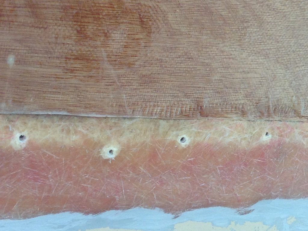
The supplies I purchased included some disposable foam brushes with which to apply the epoxy. After using one to spread out the first layer I'm not so sure this is the best method to use. I think I'm going to invest in some of those cheap "Chip Brushes" the home centers have. The individual bristles may do a better job of working the epoxy into the fiberglass cloth.
Doesn't really look like I did anything does it? I knew from videos and printed material that the cloth I'm using would become translucent once the epoxy had been worked in. I guess what I wasn't prepared for was the thinness of what I was laying down. I haven't mic'd the cloth or anything (not even sure that's possible), but it's real close to the thickness of a sheet of paper if I go by my highly calibrated (dead-on-balls accurate), eyeballs. Granted, I'll be using several more sheets of cloth and epoxy over what I've got here, but still.
One of the rules is, if the epoxy dries, sand it with 80 grit, clean the surface and continue. This stuff set up in about 15 minutes! I guess if you're experienced, you cut the next piece of cloth, get another batch of epoxy ready and keep right on rockin' and rollin'. I'm not that good, so I'm not that fast. My plan is to cut all the layers I'm going to need ahead of time then start laying down the epoxy and working it into the cloth.
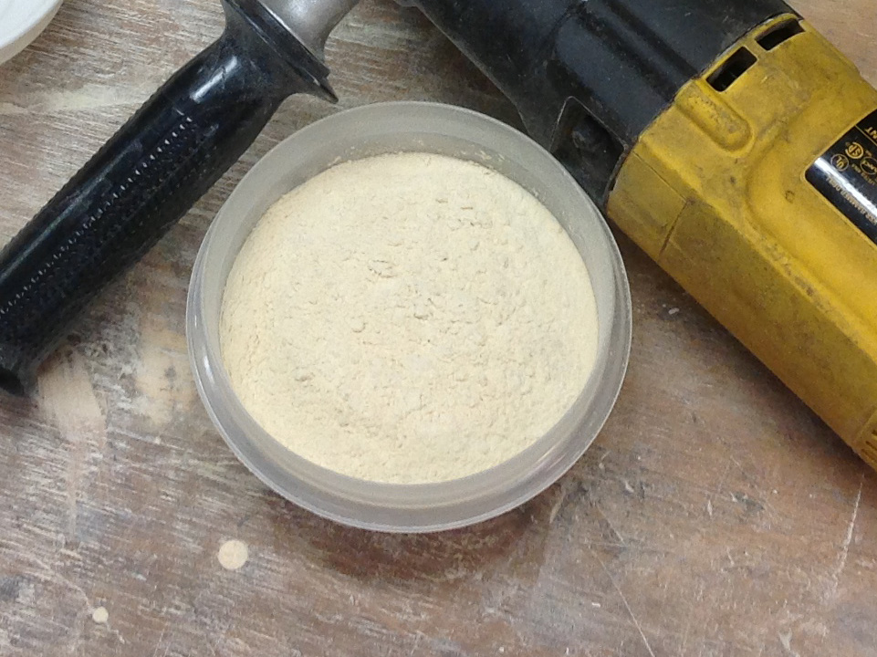
When we last left our hero, he'd brushed another coat of epoxy over the cloth, and worked some resin into the gap between the wood and the fiberglass of the roof. It was at this point that I ran into my first roadblock, as I wasn't quite sure how to bridge the gap. The advise I was given, was to bridge the gap with thickened epoxy because liquid epoxy alone would have bubbles trapped in it, creating a weak bond. I was advised to make my own "Bondo" consistancy epoxy by adding a thickening agent.
Based on this advice (and being unable to procure a pre-manufactured substance locally), I decided to make my own thickening agent known colloquially as "woodflour." With no local option (and not really wanting to waste the time driving 50 miles [one way] to the nearest West System dealer), I reluctantly assembled what was needed to make my own. Those I consulted with convinced me I could do this, AND save money in the bargain. Okay, okay... so I turned my truck around and was off to purchase some fine grit sanding disks.
The method mentioned to me, was to use a belt sander and a 2x4 to make what I needed. Which is fine. Except for one tiny little thing. The one tool not currently in my arsenal of power tools just happens to be a belt sander. So that left me with your basic 5" sanding disk backing pad and sanding disks. One and a half hours (and two numb fingers) later, I had a small pile of very fine wood powder with which I'll thicken up my epoxy. While an interesting exercise, I won't be repeating this particular procedure.
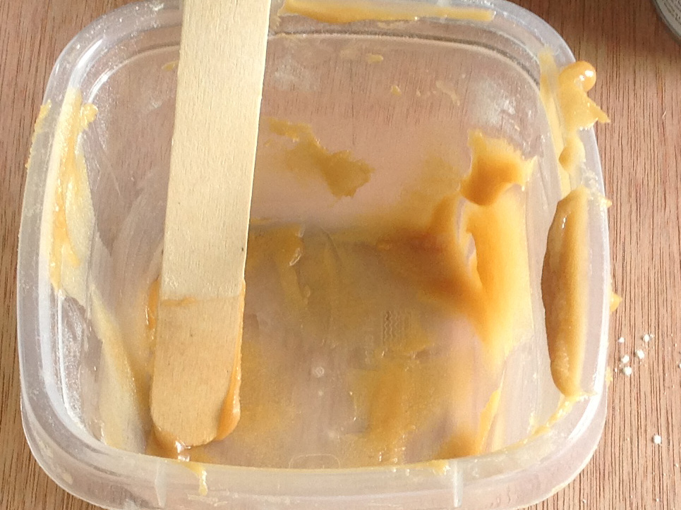
Not wanting to glop up my camera, I took a shot after I had applied the thickened epoxy to the roof of my van. Based on my experience with various brands of "Bondo" type products, I had a very real fear of this stuff curing before I had it smoothed out. As it turns out, I needn't have worried. This stuff has a much longer working time and gave me plenty of leeway to apply and smooth out the filler adequately.
Even though I'd been told I'd need about four times as much "woodflour" to thicken the epoxy, it still surprised me to add 6 plastic teaspoonfulls of the stuff to the mixture. The goal was to mix the epoxy to a consistency of peanut butter. After mixing up a batch, it's a most apt description not only in texture but color as well. It blended in quite well with the wood I'd used for a backing board. A long time ago, I picked up a package of craft sticks as seen here. I like these because of the rounded edges which make them ideal to scoop material out of corners as well as a smoothing tool when applying material.
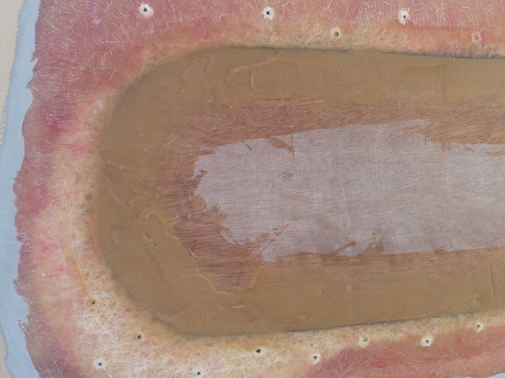
In an unusual move for me, I used an actual metal putty knife to apply the thickened epoxy, since it gave me better reach to smooth out such a long seam. I'd always used the typical plastic bondo spreaders but the putty knife also made scooping the material out of my mixing container easier as well. Before laying down this batch I sanded the built up liquid epoxy out of the step between the wood and fiberglass. I also went over the first layer of cloth lightly as well (using an 80 grit disk) to ensure maximum adhesion of the next layer.
If I'd known beforehand just how tough this stuff is to sand, I'd have made more effort to make sure it was smooth as glass. I mean I did get it smooth, but there were the inevitable lines from switching directions and going around the curved areas. After awhile though, you run the risk of messing it up by trying for perfection. So when I reached the point of "good enough" I stopped smoothing. No matter. I'm still convinced my repair will be as strong as what I would've gotten had I farmed the job out to a pro. And I'm learning how to use a new product as well.
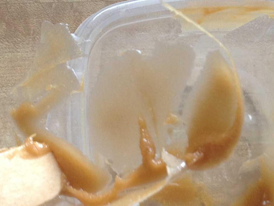
One of the advantages to using a flexible plastic mixing container. When you're done you flex the sides and the stuff you're mixing up comes right out! The home centers only had plastic paint-mixing "cups" that were way too deep (and at $4.19 each, also way too expensive) for my wallet as well as my needs.
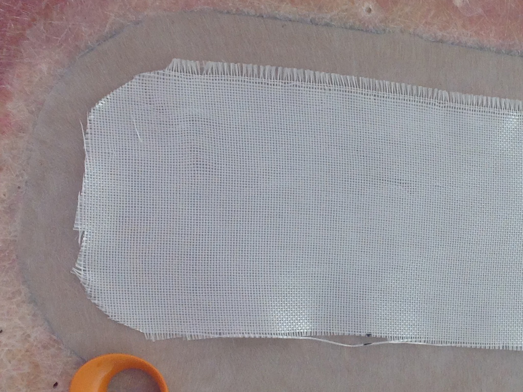
First and foremost, I have sanded the "peanut butter" smooth. It took me an inordinate amount of time to accomplish this using progressively rougher grit disks (from 100 to 80 to 40) in an attempt to find something that would cut the stuff in a reasonable amount of time. I'm not kidding. This is some of the toughest material I've worked with in quite some time. What I thought might take me half an hour or so took 3 times as long. Yet I knew I was cutting it by the amount of powder I was creating. I had to stop several times to vaccuum up the dust just so I could see what I was doing.
Secondly the scissors I purchased at Jo Ann's fabric shop. Outrageously expensive, they are nonetheless a welcome addition to my collection of tools. After fumbling around with the Chinese scissors from our kitchen drawer, I remembered buying these to use with the fabric I'll be re-upholstering the headliner with in the van. I figured the fiberglass cloth is cloth after all, so I gave these a try. Sharp, tightly machined, these babies went through the material like the proverbial hot knife through butter, leaving a nice smooth cut in the material, without tearing out individual strands. The right tools really do make all the difference.
No shots in-between layers I'm afraid, I had all I could do to cut a new (1 inch larger in diameter) layer of cloth for each successive layer. All told, I have five layers of fiberglass cloth embedded in the resin. If I manage to get it sanded smooth, it should make quite a durable and strong repair. Time will tell I suppose.
Finally layer number five just touches (I think) where the bevel begins. I was pushing at this point. I had one extra day to work on the van and the morning hours got taken up with another more pressing project, leaving me to start this right after lunch. Then I had to fight with the various grits of sanding disks in a valiant attempt to find the one that would actually cut the epoxy.
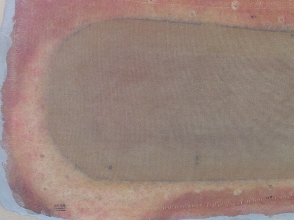
With the "peanut butter" layer finally sanded, I took a break (of sorts) and gave our dog a much needed bath. Then, while he dried off I could move on to the epoxy/cloth build up phase. With roughly 15 minutes between layers (to where I could just leave a fingernail impression in the stuff before the next piece of cloth was needed), I was trapped into a loop of apply...wait/cut...apply until 6:30 in the evening.
All that remains now is to purchase a compatable thickening agent from West Marine to mix up a "Bondo" style batch of filler as my final fairing coat. I'll use this layer to fill in any gaps, depressions or grooves left by my application methods. Then I can sand that final layer smooth, shoot it with some epoxy primer, top coat it with color and clear and my roof will be weather tight once more.
Holy crap! This sounded like such a simple project when it was being discussed. Now that I'm in the thick of it, I realize just what I've taken on here. There's no stopping now if I want to make the Great Southern Van Run on October the first. That particular event is barreling down on me like a runaway freight train and I still have the other side to do!
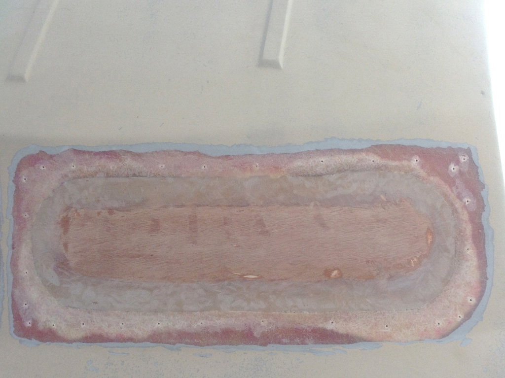
While I was waiting on the guys to come and install our carport, I decided to have at the driver's side layer of peanut butter so I could begin laying down layers of epoxy and cloth. Once again it was a real endurance test (of both me and my tools), as my made in China die grinder vibrated the threaded collar around the shaft loose. So it was down to the shop to attempt to thread the collar back into place.
This go around, I stuck with the 40 grit 2 inch disks. They cut the best and with a 2 inch diameter don't bog down like the 3 inch disks do. By the time I was done I really didn't have any energy left to attempt the layering of the 'glass, so I'll do that next time.
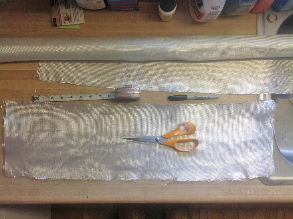
For this session, I decided to cut all my pieces of fiberglass cloth ahead of time, instead of in between layers. The advantage to this approach is I don't have to measure for the next layer while the previous layer is still curing. There seems to be plenty of curing time to cut the next piece, but I wanted to see if this method worked any better.
Once again I'm usurping our kitchen counter and using my measure, mark, cut method. The hardest part of this step (other than getting the cuts straight), is rounding off each corner. It's not real easy to hold limp, slippery cloth like this and make a nice rounded semi-circle on each corner. But I'm not sweating the details too much as this will all be covered with a thickened epoxy layer prior to painting anyway.
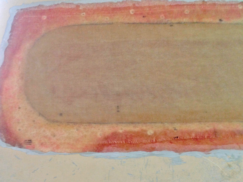
As before, the translucent nature of the cloth makes the photos look like I haven't done anything. One downside to pre-cutting all my layers of cloth is waiting for each layer to cure. It was taking 15-20 minutes for each layer to get to the point where I could just leave an impression in the surface, meaning it was time for the next layer.
At one point I went inside and watched one of those car-buildup shows while I waited for the previous layer to cure. The hardener I'm using is labeled as "Fast" on the can. I'll say this much, if this is their idea of fast, I'd hate to see their concept of slow. I've now got 5 layers of cloth on each side and will lay down more resin with a thickening additive used to control the viscosity of epoxy (using West System's 406 Colloidal Silica) as my next step towards completion of the repair. Touted as being strong, I just hope it's not too hard to sand.
When making my initial purchase of materials, I picked up some of West's 410 filler recommended to me for a light, easily worked fairing compound especially suited for large areas. I told the guy helping me that I was working on the roof of a van, but he failed to mention that the 410 is not recommended under dark paint or surfaces subject to high temperatures. Is sitting out in the August heat in a parking lot considered a high temperature? I may have to do more research on this.
The A.D.D. Vanner
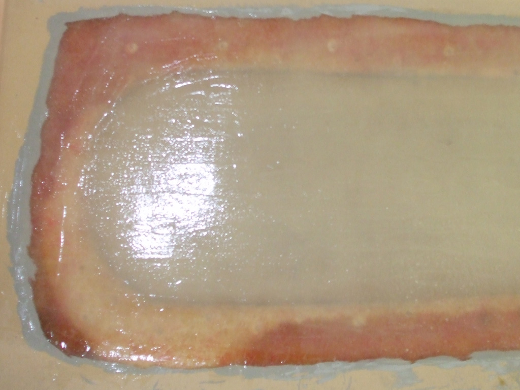
After a brief tour through the intricacies of the cooling system it was time to turn my attentions back to my "fiberglassing the roof" project. Although almost impossible to see (due to the translucent nature of the epoxy), I began laying down layers of epoxy resin (thickened with the colloidal silica) mixed to a peanut butter like consistency over my previous fiberglass cloth laminations.
I actually ended up using the 406 Colloidal Silica instead of the 410 Fairing Filler due to the temperature restrictions of the 410. Also, the West Marine store I went to was out of the 205 fast hardener, so I had to resort to the 206 slow hardener. Being the Friday before I hoped to primer the epoxy, I had to "shift project gears" on the fly.
By the time I returned from my safari to the West Marine store (as well as other must-do errands), it was nearly 5 o'clock. Between the slower curing hardener and the lateness of the time, this meant I just had to mix more epoxy for a thicker layer in one pass. Let me tell you, I ladled this stuff on with a trowel in my attempt to meet my self-imposed deadline. My maximum mix prior to this had been 3 pumps of epoxy/hardener, this time... 7 pumps of each! Now all I had to do was let it cure.
September 2013
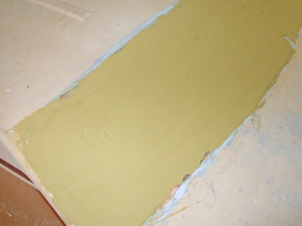
The Saturday just before GSVR IX I reached a milestone. I spent the day preparing the roof with a skimcoat of fiberglass. This was tricky to pull off since the patch area was so big. I used a wide knife and only got to make about 3-4 passes before it started to cure. Hopefully it will fill in all the low spots and I can cover the whole area with some epoxy primer I recently purchased... after my roadtrip. So much for my "master plan".
Ultraviolet light and epoxy resin do not get along, hence my rush to get it was protected for its first big roadtrip since I performed all my repairs. As long as I keep it under cover I think I should be okay until I get it primed. Then I can prep the gutter area, prime that and lay down some new seam sealer. Shoot it with some body color and I will feel confident going out in weather that's less than perfect.
Sounds simple enough, doesn't it? If you've ever sanded (or tried to sand) epoxy resin, then you'd understand. I started with 80 grit, eventually moving down to 40 grit and still it seemed like the "Never Ending Task" just to get the stuff sanded enough for a skim coat of fiberglass filler. I thought this sanding job would never end. I could tell by the sanding dust I was doing something, but the progress was glacial at best. I may have accidentally created the world's first bullet-proof roof for a van!
October 2013
I'd visited my FIL at a previous GSVR event a couple of years ago. Even though my van was "a work in progress" I threw it back together enough to make the day trip. Mainly I re-installed the battery tray, battery, radiator and made sure there were no leaks or other loose ends before we took off. The van performed flawlessly for our Saturday adventure. Although I've driven pickup trucks for years, the van feels rather ponderous and tippy at times. The brakes still need to be gone through (but I've got a running van!) before I can press it into daily service. The only downside was some dry-rotted wood falling down from up above periodically.
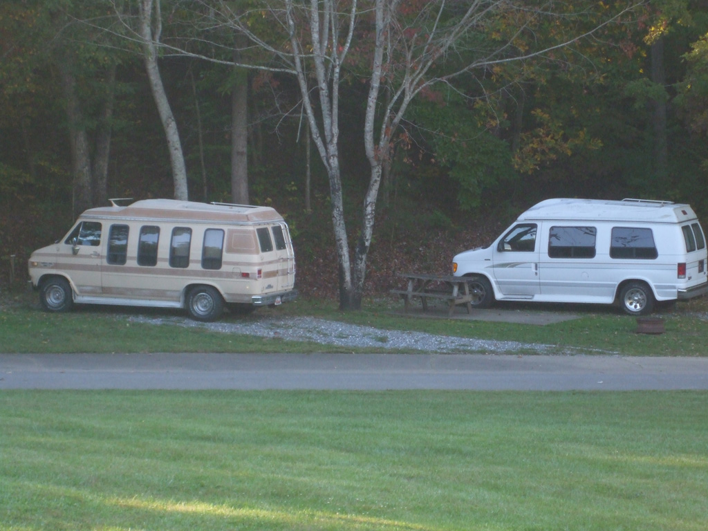
We only attended for one day this year, earlier plans for a Friday overnight stay having fallen by the wayside. Instead, we got an early start Saturday morning, had breakfast and headed up to the Flaming Arrow campground. It was a real experience to caravan down the mainstreet of the local town to line up all the vans for a display at a local strip mall. The only downside was an early October heat wave with upper 80's temps driving folks to seek relief in some of the nearby stores.
The drooping headliner in my Monte SS about drove me up the wall, and wood splinters sprinkled on my noggin is not an improvement by any stretch of the imagination. So, the Sunday following the GSVR (Great Southern Van Run) event, I bit the bullet and began removing all the old water damaged wood from the steel roof above the cockpit area. Veering off from the bodywork to tackle the interior has led me to label myself as a practitioner of the Attention Defecit Disordered approach to vanning.
Back to the Railroad
April 2014
After GSVR IX, the big boy went into hibernation for the winter months. I didn't want to get caught out in the rain with my naked body filler, not to mention my rusty gutters - what little remains of the cracked factory sealer still clinging rather tenuously to the steel. My master plan was to finish the fiberglass, sand the entire roof (where the factory top coat is gradually eroding, exposing the factory primer), prime it, re-seal it and top coat it. No lofty goals here.
Thankfully I now have a steel carport to shelter my van from the elements and since I have another daily driver, hibernation seemed like a good idea. Work continued of course, just not outside work. This is where I logged a lot of time on my cupholder project, overhead console project and other non-van related household chores. Typical winter stuff.
But now? Now it was time to get back on it. I started with 100 grit, (preceded with a little cheese grater action on the ridges left by the spreader), stopping frequently to remove the sanding dust. I used a 15 inch long board for this phase of the operation. I Sanded back and forth in an X pattern to get the surface as level as possible.
The filler we used was Evercoat XTreme, and I've definately got to pick up some more of this stuff! It sanded like a dream with 100 grit. I can remember using the old pink Bondo back in the day and the waxy coating that would clog up your 60 grit sandpaper in no time flat.
I had spent quite a bit of time pondering just how I was going to perch up here to complete this particular task. In the end, I threw down a piece of plywood (day job = spare/rear storage cover), to spread my weight better. By using a 10' ladder to gain access I was able to kneel up there and attend to business. The sun was baking me nicely, but I had tunes on the radio and soda in the garage, so I "pressed on."
Using a long board like this, helps even the surface without cutting grooves in the surface as easily as one would, using a smaller pad. The alternating diagonal pattern helps too. The nice thing is, this area isn't that noticable from the ground if I make a mistake. My goal though (as always), is to not make any.
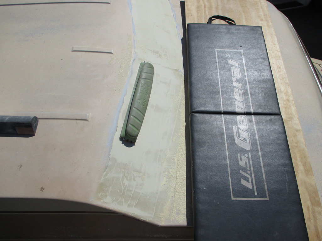
One thing became apparent rather quickly... my 52 year old knees did not appreciate being pressed into service kneeling on such a hard surface. Fortunately, I had a solution sitting in the corner of the garage in the form of a pad designed to be used to lay on beneath a car or truck as its being worked on. I laid it across the plywood and Presto! my knees were happy once again.
This side took me more time to complete for some reason. I'm not sure if the filler was thicker on this side, or I was simply getting tired. Probably a little of both. I didn't really get started until around 1:30 or so and by six o'clock it was definately time to pack it in. My dog wanted his supper anyway so I fed him and began packing up all the tools and such.
I didn't go any finer than the 100 grit for now. Another layer will need to be applied and I want to make sure the bond will be as strong as possible. My plan at this point is to apply another layer, hit it with 100, then some epoxy primer. Next, I'll sand the primer with 180 grit before color. For the rest of the roof, I'll use 180 to get down to the factory primer (80 if I hit a tough spot), then shoot the roof with color. Stripes will come later. If I stripe it, I'll need to use base coat/clear coat for a smooth finish.
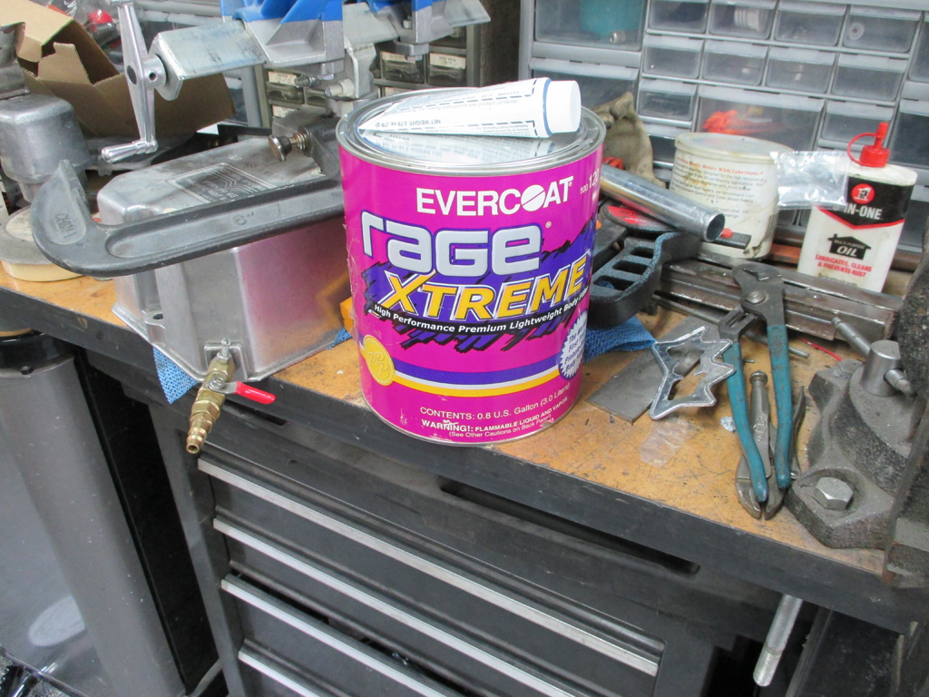
You know, for $50 bucks (not including shipping), I would have at least expected a full gallon of stuff. When I opened up the can, I was surprized that there wasn't a full can of fiberglass... until I read the label. First tuna cans in the supermarket began shrinking (although the price always stays the same or goes higher, naturally), then my dog's food did the same thing. Now I don't even get a full gallon of filler? Who sells 0.8 gallons of anything?
Philosophical rant aside, I ordered some of Evercoat's Rage X-treme premium body filler from Summit Racing. I was surprized that they carried the stuff, but they had the best price on the 'net, so I took the plunge. I used a 4" putty knife (not the best choice), to ladle it out of the can and the stuff has the consistency of pancake batter. Runs all over the place like pancake batter too. It probably didn't help matters any that I was using this filler on a bright, sunny 90* day either.
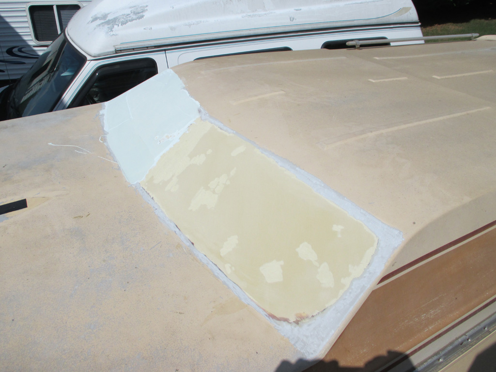
Work on the roof continues to progress despite other "in between" projects like installing a new front passenger seat. Having previously sanded both sides with 100 grit, this time I roughened up the low spots and laid down another layer. The filler generates heat as it cures. Troweling it onto a hot surface that's been sitting in the sun only made it cure faster. I barely got 80% of what I'd mixed onto the surface when it began to set up. Then I couldn't get the cured material off the painted steel scrap I had used as a mixing tray. A hammer and cold chisel removed some of the larger chunks, but it was crazy adhesive on a painted metal surface no less!
With nothing else handy to mix the filler on, I concentrated on surface preparation instead. On the passenger side, I hit the high narrow ridges with the old "cheese grater" then removed some other unnecessary blobs with some 40 grit. Then it was on to the driver's side, where I used the same 2" 40 grit disc to prep the low spots from the previous layer of filler. I plan on waiting until I have some shade (probably at my place) to continue the filler work. I've got some disposable aluminum baking pans I'm going to test out as mixing trays. If that doesn't work out, I'll sniff out some plastic trays or something at the local Good Will store.
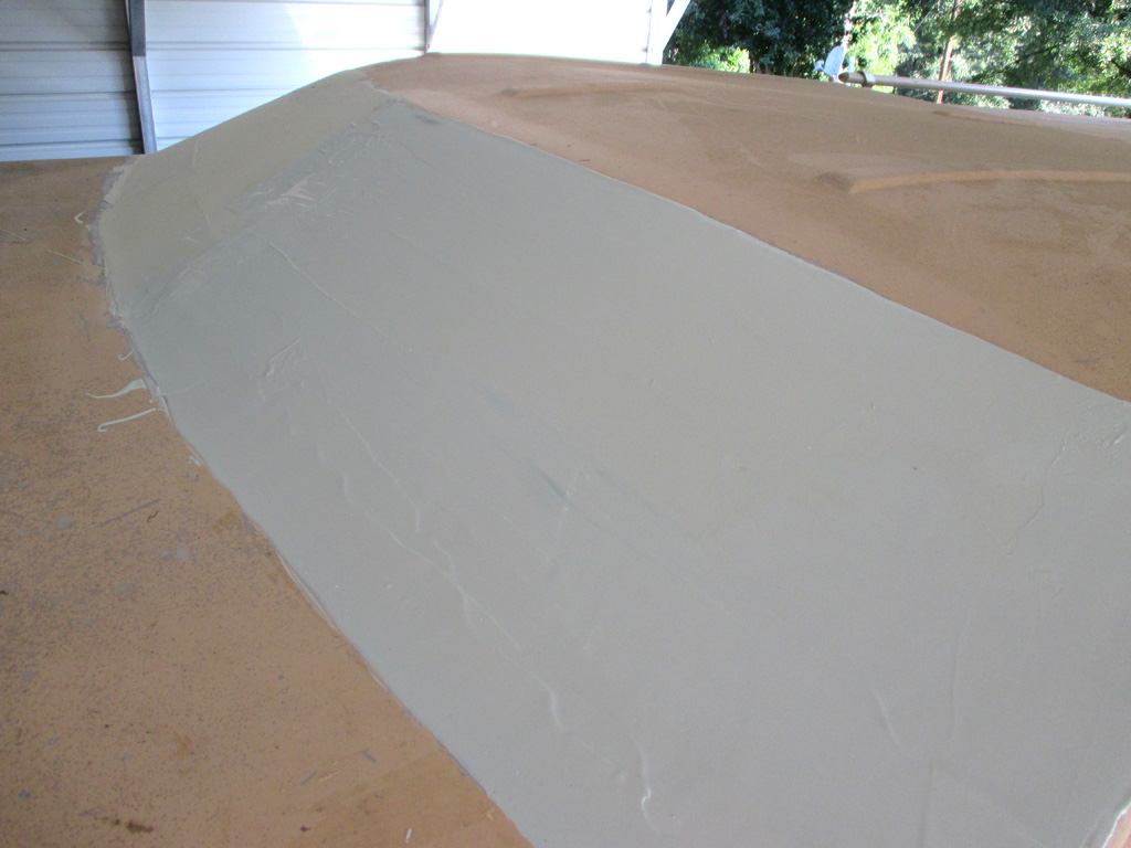
A couple of weeks have passed since I was last up on the roof. I finally got a few good days in the 80's with very low humidity for a change. So I whipped out my new mixing tray and mixed up a big batch to skim coat the driver's side of the roof. It's somewhat of a black art - knowing how long to mix both parts of the filler before climbing up on the step ladder to apply the filler. Mix it too long and it hardens in the mixing tray. Don't mix it enough (or don't use enough hardener) and you have to remove the uncured fiberglass from the surface and start over again.
The first step was to vacuum off the surface to be sure it's as clean as possible without resorting to solvents which would get absorbed by the previous layer of filler. My first big batch of filler got most of this side covered. Then it was time to mix up a smaller batch to fill the bottom third of the area I was working on. Thankfully once I saw the hardener was completely mixed in I grabbed the mixing tray and hustled up the ladder. Each time I made it with time to spare. My sincerest hope is that I will only have to sand this slightly to level it out and then paint it.
With the windows gone, I'm modifying this area to make it flow a little better. Originally, this area had a vertical ridge in the center and each window had a 2 inch border between the edge of the glass and the edge of the roof. I'm attempting to follow the contour of the roof in one smooth continuous arc (horizontally from edge to edge), whereas the original had a peak or ridge in the center. My first attempt had been to just fill the glass openings, but I hope this will be a better look for the roof.
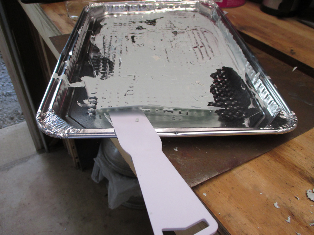
Since I didn't have any dynamite on hand to remove my previous layer of X-Treme from the section of sheet metal I used as a mixing tray previously, I flipped the sheet metal over using the clean side to support the new aluminum cooking sheet this time out as my mixing tray. The leftovers from batch number one peeled off easily with just a little flexing of the tray and some pressure on the plastic putty knife. Batch number two's leftovers were a lot tougher to remove, requiring lots of flexing and heavy-handed scraping. The scraper ran through the side lip of the tray in several places. So for this episode, two batches is the limit for the foil baking tray. My next tactic will be some non stick aluminum foil to line the baking tray.
Not sure if it'll work or not, but hopefully I won't need to find out right away. That's if the filler already on the roof sands out level enough to paint without further layers of filler. Kind of a big IF, but I was pretty close with the previous batch, I just removed too much material in an attempt to follow the original contour of the roof. This time I'm doing things my way which will look just as good and be weather proof... finally. I've got a couple other places where I may need some filler, so I don't want to use it all up on this area if at all possible. I'd love to make this one can suffice for all the repairs the van needs.
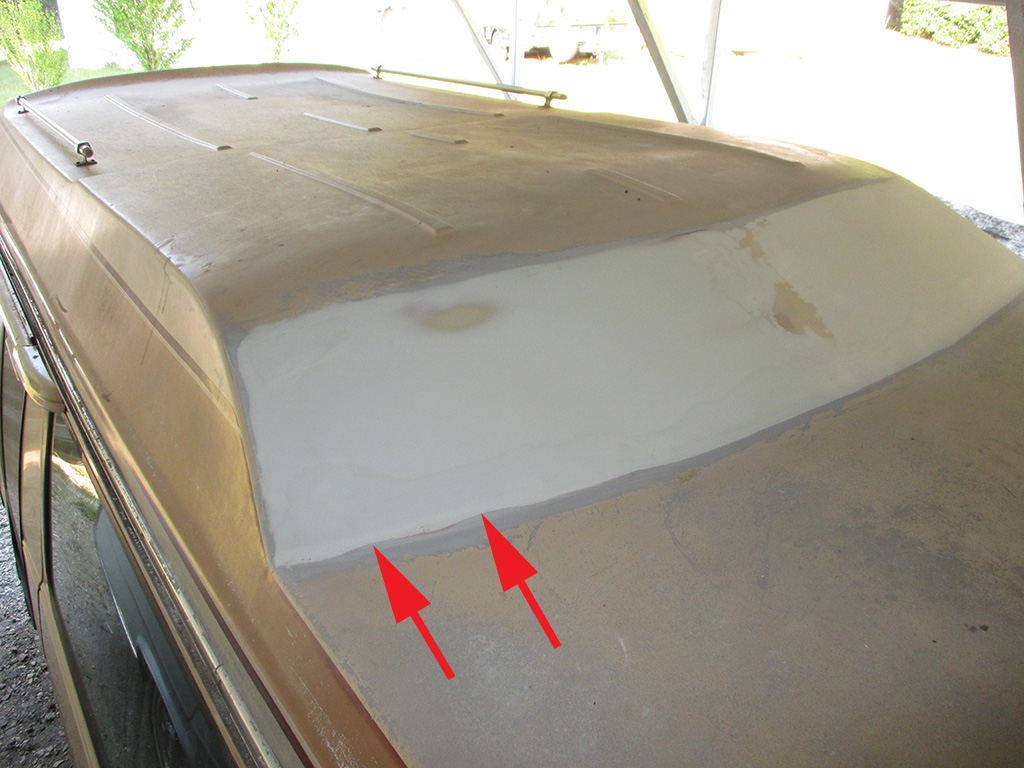
I was fairly aggressive in sanding down this layer. Here's an example of what can happen when you do this and you still have low spots... they become even lower! CRAP! Once you're in it this far, there's nothing else to do but press on. I continued with my sanding across the whole patch watching carefully for the layer beneath to appear so I'd know when to stop.
The red arrows denote two really noticeable low spots (there were several others) meaning at the very least I needed to make another pass across the bottom where I was fairing in the new fiberglass. This is why bodywork takes me so long to finish. Put on 4 pounds of filler, take off 3.75, repeat. At least using better sanding boards (not to mention higher quality sandpaper), has contributed to a better overall repair.
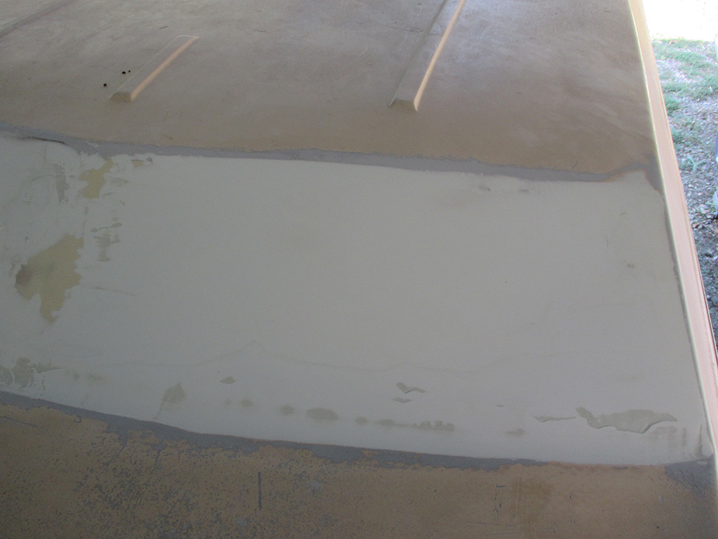
When I laid down my last batch, I was convinced I wouldn't need any more layers since I laid this one on fairly thick. WRONG! One of the key advantages to using a long board (even if it is only 15"), is that it does a much better job of only hitting the high spots than the old 4" rubber 3M block I used way back when. Obviously I was wildly over-optimistic.
I had low spots on each outer edge, the center section and all along the bottom edge. It actually resembled a big squared off, really wide letter W when viewed head on. With the main surface leveled off, I used some 40 grit to rough up all the craters and mixed up another batch of filler. It was hot and humid, so when it looked like it was well mixed I charged up the step ladder and applied another layer.
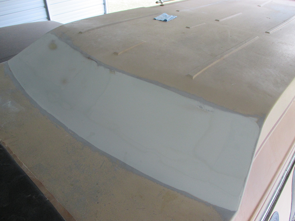
If you look closely you can see the bottom edge pass I made as well as the W layer pass I made. Even after the W layer I STILL HAD LOW SPOTS along the bottom edge. Is this ever going to end? There comes a point where you have to seriously consider perfection vs. time and energy spent in the pursuit of same. I was rapidly getting to the point where enough was (almost, not quite) enough.
The only positive spin I could put on it at this point was each batch of filler I mixed was getting progressively smaller. Of course that opened up a whole other can of worms regarding the ratio of filler to hardener. I was so used to larger batches I over-hardened the smaller batches and had to move like lightning before it flashed over. Each pass was getting smaller as the heat and humidity pressed down like a lead weight.
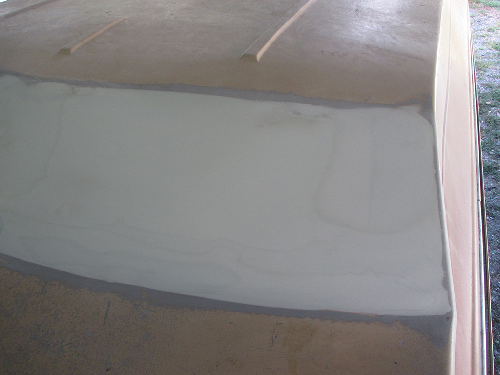
Unfortunately (or fortunately depending upon how you look at it), the perfectionist in me was still driving the bus. I made yet another pass along the bottom edge in another attempt to banish forever all the low spots that I knew would look like hell in the final paint job. Is this ever going to end? I was drinking water like there was no tomorrow in a valiant attempt to stave off heat prostration. But as the day slowly wore on, my patience was dwindling rapidly.
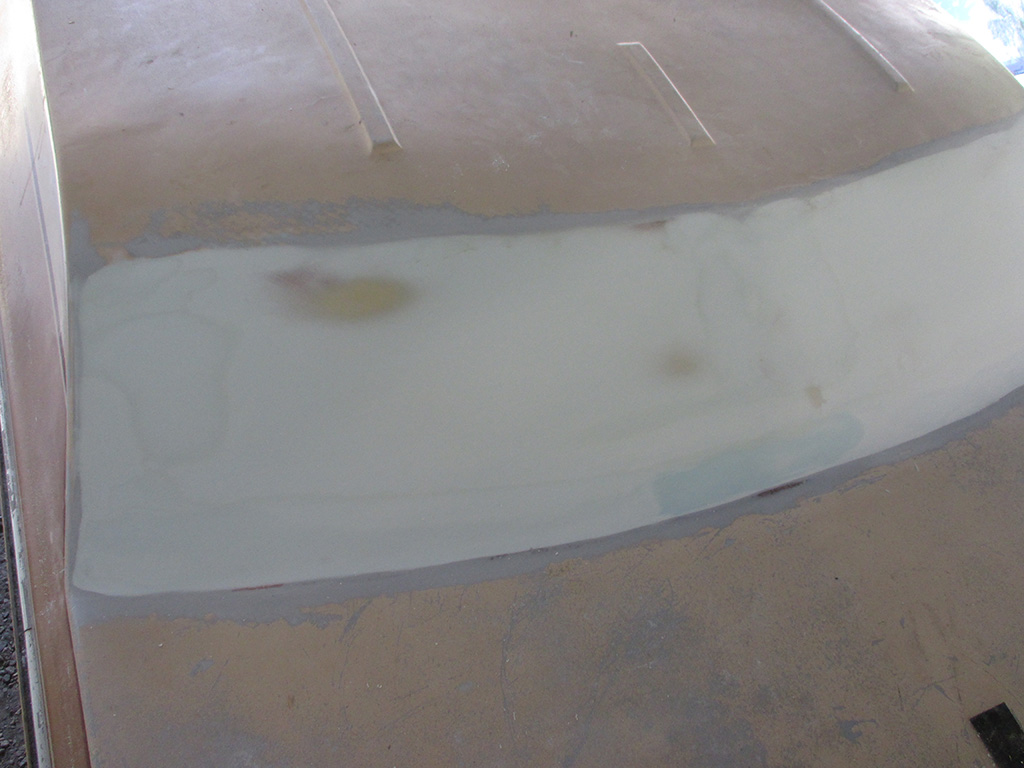
By this point my initial goal of making this area perfect began to fade. The project wore me down to the point where I'd be satisfied with "pretty damn close" to perfect. At this point there was only one last low spot remaining near the bottom center (necessitating another excursion up onto the roof), of the repair area. To keep from sanding the surrounding area down too far, I sanded this small area with some 120 grit by hand until the edges were well feathered out. Then I felt comfortable making a light pass with the sanding board for a final blending.

Put a fork in me, I'm done. At this point there's nothing left I can do to make this any better. In the end I feel I've done the best I can do (without primer and a guide coat and more sanding), to make a professional repair to the roof of my van. At the very least, I need to get a couple coats of epoxy primer on this and see how the final result actually looks. I've got my compressor, 120 sanding disks and DA sander waiting in the wings to prep the rest of the roof for paint. This was the big hurdle I had to clear before moving on to the next step.
Rain Gutter Caulking
September 2014
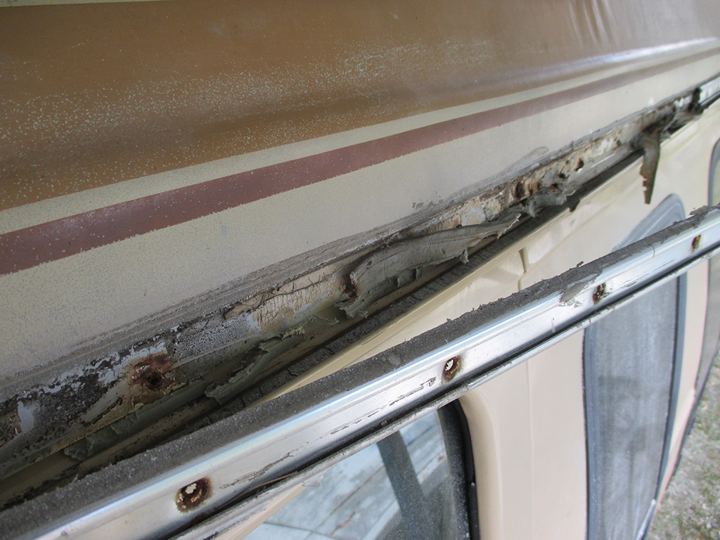
With the newly window-less panel finally prepared to my satisfaction, I am able to move forward with the rest of the necessary preparations. With that in mind, I set about removing all the trim (not to mention the aluminum roof rack bars), so I can clean and sand the roof for paint. This is where I returned to more familiar territory of getting everything ready for paint, after getting bogged down in filling and sanding.
I must admit I wasn't quite prepared for what lay behing the aluminum trim. Since someone had gone through the trouble of running a thick bead of silicone sealer along the top edge of the aluminum band, I sort of assumed there was no sealer behind it. Wrong!
Caulking tape! I haven't laid eyes on this kind of stuff in a good many years. My Dad had a couple of rolls he inherited from my uncle back before I even had my license. Soft, pliable and super-sticky, the stuff came in rolls with a wax paper backing you had to peel off and if you stacked the rolls, they got stuck together along the exposed edges.
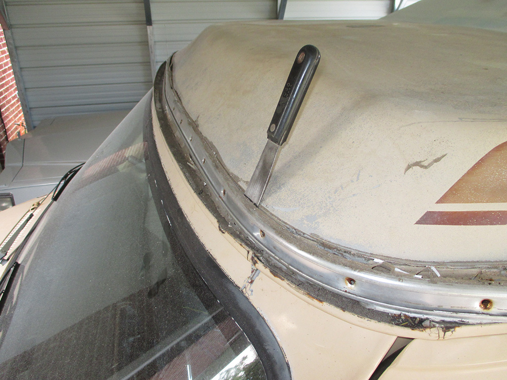
I ran the tip of my putty knife along the bead of silicone at about a 45* angle to cut through it, then began the process of gently prying the trim free from the caulk. One of the previous owners also went the extra mile and "finger-smeared" some silicone over the gutter caulking in an all-out attempt to stop the water leaks. My plan is to remove all of this. Then I'll wire wheel the gutters, lay down some epoxy primer and then a high quality 2k seam sealing product (leaning heavily towards Lord Fusor at the moment), which will then be primed and painted with the color coat.
The tricky part as I see it is keeping it dry between the wire wheel treatment (solvent cleanup too), and application of the first coat of primer. Hopefully the high end seam sealers have improved a bit since 1984. My overall plan is to do this job once and do it right! I could see water/rust marks along the inside of the roof, but whether or not that was from the skylight leaks or the failure of the gutter sealant is unknown at this point. Hopefully my all out attack on the water leaks will yield a van I can take out in all weather. Right now if the sun isn't out, I don't take the van out.
With the trim removed, it was time to get down to business. I ran a plastic putty knife at a sharp angle to remove the remnants of the bead of silicone. Then I reduced my angle of attack and made a horizontal pass to remove the rolled caulk from the fiberglass roof. I'll probably have fun trying to find new stuff when the time comes.
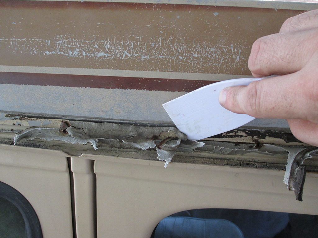
STEP 1
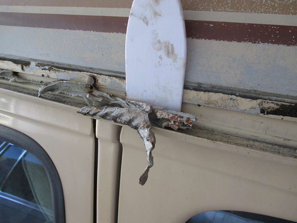
STEP 2
Step two found me sliding the blade sideways along the bottom lip of the fiberglass, then twisting the knife down to get the caulk out from behind the lip. Then I put the knife flat against the metal and pressed down and out removing the caulk from the original steel of the roof. This removed 98% of the goop, I'll follow up later with some solvent to remove any residue.
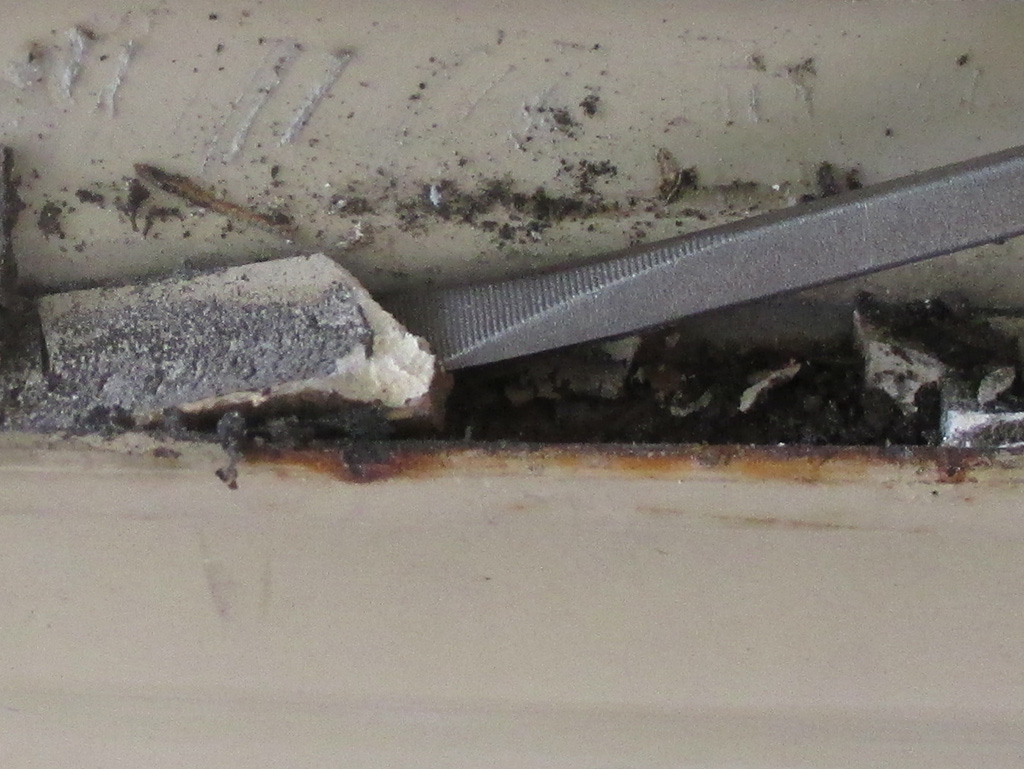
I could see cracks in the gutter sealer and the gutter itself was about the width of your average flat-blade screwdriver. What would you do in this situation? Me too. I didn't have to tap too hard with my hammer either. Judging from how the rust is coming over the lip of the gutter, this is one place where water (if not getting inside the van), had nonetheless been rusting out the gutters.
The real issue of course, is the way the van was originally built. There are at least 3 different layers of steel all coming together in one place. It would have helped if the top layer folded over the gutter so the seal would have been on the underside of the drip rail. Monday morning quarter-backing aside, the design was probably more cost effective for the factory to build. Got to keep the old profit margin nice and fat for the stock holders after all.
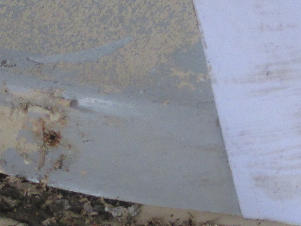
As I was wielding my putty knife with wild abandon, I noticed a couple of things. The original paint was coming off with the silicone sealer and the caulking tape. Beneath the paint, the fiberglass gel coat is glossy. Everything I've been learning up to this point hinges on the paint having enough "tooth" to grab onto. If the original gel coat was glossy, then the surface (in my humble opinion), wouldn't have enough tooth to promote good adhesion of the paint.
This might explain why the paint is checked all over the roof. This should make sanding it off relatively easy, so my plan is to start with 120 grit and see how that goes. I tested this on a small side section to see how well it would go through the painted stripes and base color beneath. The 120 seemed to do the job and leave some tooth in the gel coat for the paint to grab onto. I hope. If nothing else I should have a nice weather tight roof when I'm finished. The gray caulking tape seems to have a moist, almost oily texture that seems to have penetrated (and then loosened) the paint where it was used. Not sure yet what I'll use when the time comes to replace the aluminum trim.
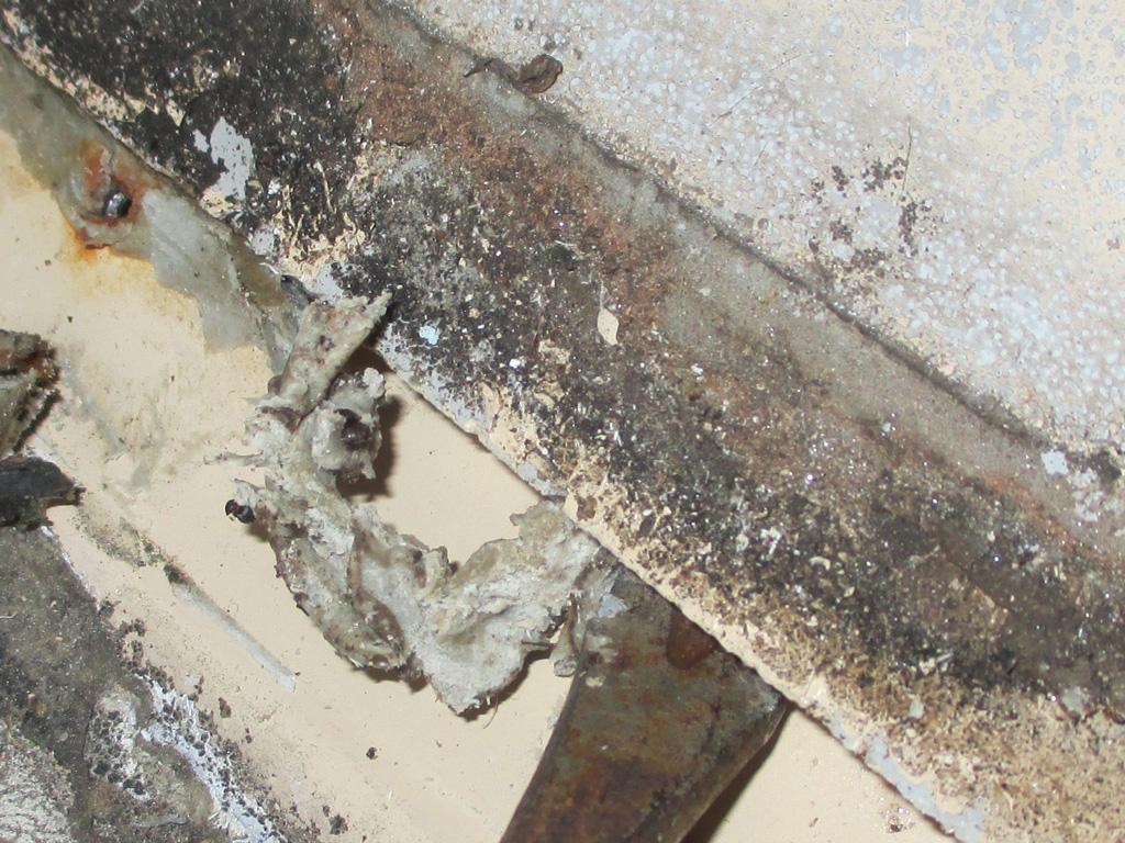
I have found more uses for this little tool than virtually anything else in my toolbox. I found it in the trunk of a car I purchased so long ago I no longer remember which car it was. In this case, I needed a tool to remove the strip caulking which in some places was between the lip of the fiberglass high top and to original steel roof of the van. What I really needed was a putty knife with a curved leading edge. This little baby immediately came to mind. I'm not sure whether I can purchase a newer version of this stuff or whether I'll find a better substitute. Either way, I'll want to remove as much of this old stuff as possible and that's what led me to this.
If you click to zoom in, you can see how well this gizmo worked for me here. I used a couple of regular putty knives (out of frame in this shot), on either side to gently pry up giving me room to scrape off the old caulk. I decided to tackle this first, then I'll come back and hit the gutters last. That way the gutters will be exposed the least amount of time before I shoot the primer. At least that's the plan right now. Once I get all this damned caulk cleaned off, I'll sand the roof then clean and wire wheel the gutters. I kind of wish the job went as quickly as it takes to type it out on my computer, but no such luck.
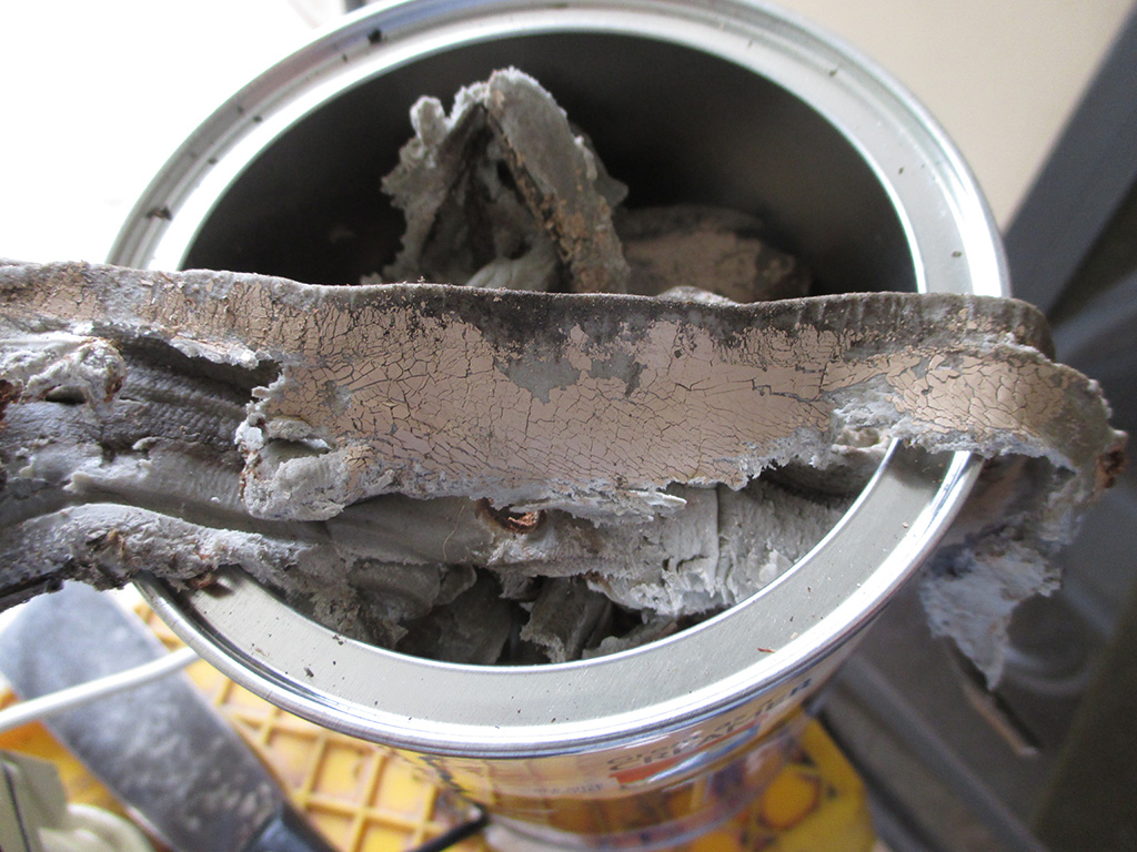
Hours later, I'd managed to fill two coffee cans (albeit the new smaller ones), with all the caulk I managed to scrape off. This part of the operation was a real drag. I found that if I stood on the ground looking up at the lip of the fiberglass roof, I could see where I still had residue to remove. This is probably why I procrastinated for so long on this stage of the project. I knew it was going to be a real ball buster and kept finding other things to do that were easier. Now I have no choice.
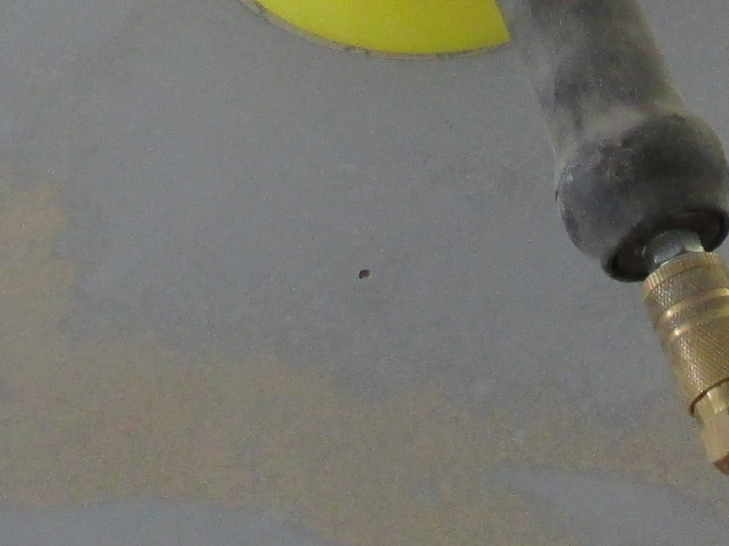
I really should've gotten to this stage much earlier. The original plan was to sand and primer the roof, then hit it with some matching color following the great window removal project. Couple of things got in the way. Every time I ran my compressor for too long I'd trip the breaker in my shop. This necessitated purchase of a 50' roll of 10/2-G wire and a new 30 amp breaker. It took me most of one whole day to complete that little task.
My garden tractor kept breaking down, the rain kept falling, I had grass up to my knees and only a 19" hand-mower to use against it. I eventually resuscitated my Dad's old John Deere from its 8 year hibernation (eating up another 3 days), and finally beat the grass back into submission. I ordered a Hookit sanding pad for my DA (dual action) sander and two boxes of Hookit sanding disks to use with it.
The 120 grit seems to work just fine, although it's a little hard to figure out when the disk stops cutting the paint and needs changing. I'm also learning how to manipulate the sander regarding speed and pressure. I discovered several pin holes in the surface of the fiberglass roof as well. Not sure how (or even if), I'll address those when the time comes.
October 2014 - Pushing Hard
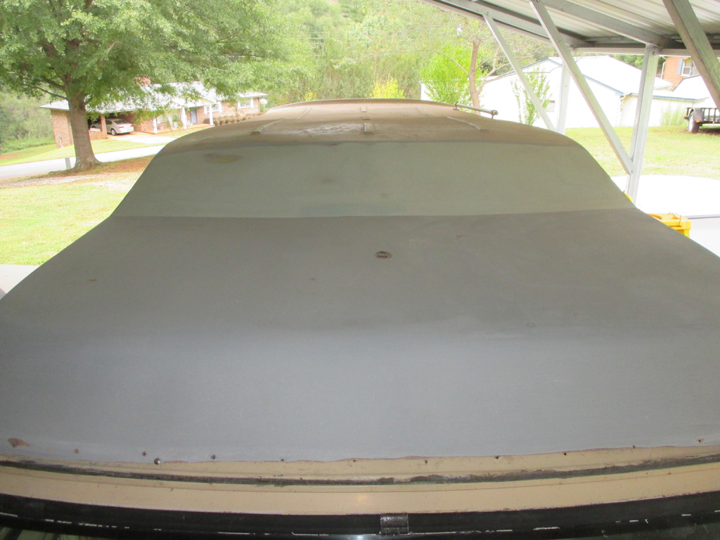
Until you've spent several hours leaning over the roof of a van (tenuously clinging to your step ladder), you don't realize just how big a task you've actually taken on. I can only imagine what an auto body shop would charge for a job like this. You've got time and materials to consider and then there's the physical size of this behemoth. Of course I like to think a body shop would have some sort of scaffolding to make the job a little easier, but what do I know. As a DIY project, I ordered what I needed for the task and jumped right in. This may be why I procrastinated doing other things on the van until now, with a feel of autumn in the air I really need to get my rear in gear.
I removed the two luggage rails from the back 1/3rd of the roof, held in place with some nice rusty phillips head screws. I guess aluminum or stainless steel would've been too expensive, but hell, there are only eight or so screws. I had to use my vise-grip pliers to break four of them loose, while the others actually worked the way screws are supposed to work. That little task slowed the project down some too. I believe I'm ready for this part of the project to be done already. Got lots of sanding to finish first though.
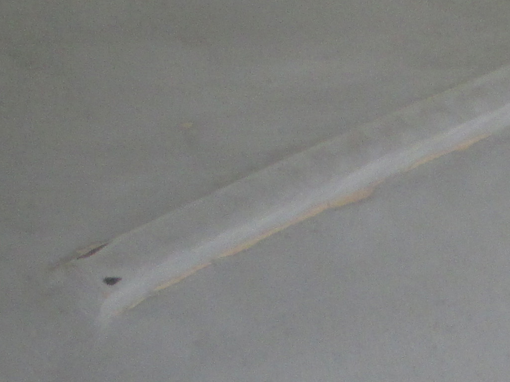
By the end of the first day of real sanding, I'd gotten to this point. This was on a Friday and if I really haul ass maybe... just maybe I can shoot some primer on this thing next Saturday. The weather conditions look favorable, but beyond 2 days out the weather guys are really just guessing anyway. In order to meet this totally insane rather ambitious goal I'll need to be out here after work in the evenings. Not sure what my energy level will be like by that point, but I'm going to give it the old college try.
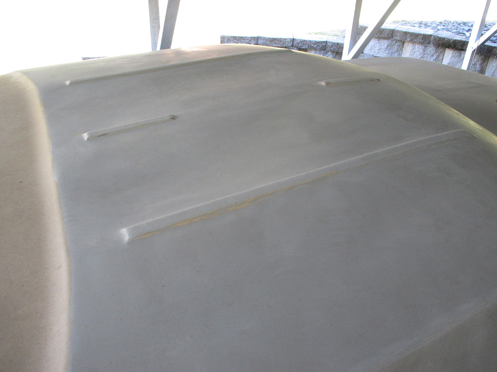
Tuesday evening I managed to cram in a little over an hour and a half of sanding, which basically got me to this point. I still suck at estimating when I need to change sanding disks, going with the "when it stops cutting it's time" rule so far. Since changing disks involves disconnecting the sander, climbing down off the ladder, going into the shop for another disk, then returning to my precarious perch once again, I tend to get lazy. Rather than go through the procedure outlined previously it's easier to just... press a little harder. Eventually though, you have to make the safari into the shop for a new disk and some liquid refreshment.
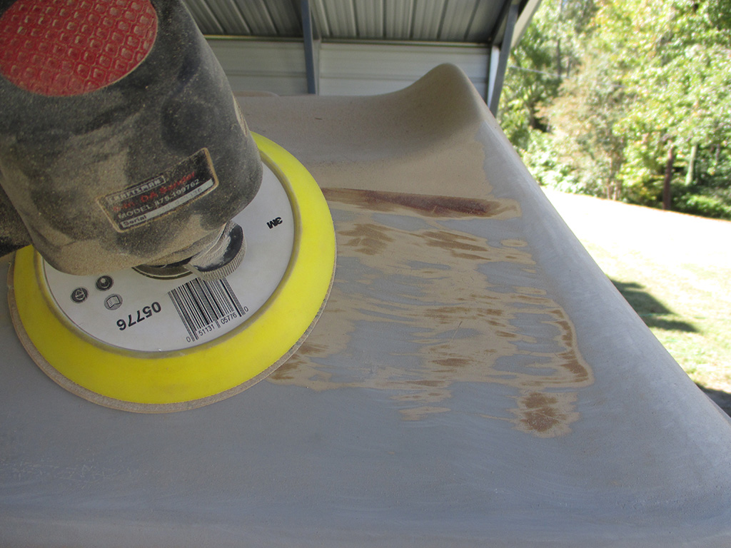
It took me quite a bit of work to cut through the brown stripe that had been painted over the tan base color. There was no "burying the stripes in the clear-coat" method used on this van. If you ran your fingers over the stripes, you could feel that they were higher, meaning they got painted on last. My plan is to replicate the way the van was painted back in the day. For starters, I won't have to worry about my clear flaking or peeling off several years down the road. Instead of stripes, I'm going retro with a geometric design currently taking up residence in my head. A template, some wide masking tape and I'll have this thing looking groovy again in short order.
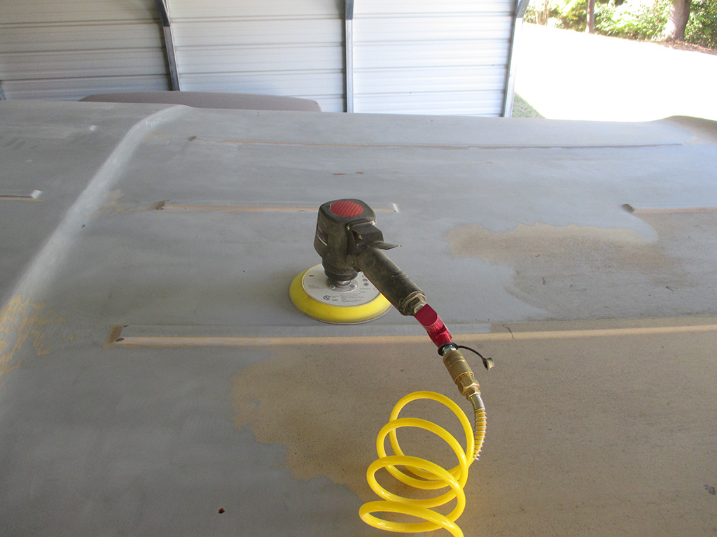
Saturday I went to my local paint shop and purchased a disposable respirator for this part of the project. If nothing else it should give me a feel for how these things fit and its adjustable. Everything I've been reading urges the use of a positive pressure "supplied air" system with a hood of some sort as the best method of protection. I just don't happen to have $400 bucks sitting around to purchase that type of system. I'm not sure at this point, but I may be spending just shy of that amount on the paint and the paint is what I need for the van.
I pissed away most of Saturday doing yard work, so Sunday I was back on the van. I actually managed to sand 98% of the roof by day's end. If I got too close to the ribs in the roof with the DA, I burned through the factory coating. I tried my best to get close, but not too close. For the fine lines that remain around each rib, the plan is to hand block sand them so I'll have better control.
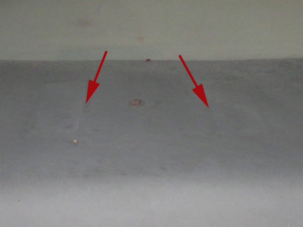
Now. . . I'd been told to keep the DA sander as flat as possible during use, to leave as flat a surface as possible. Did I listen to that advice? Not a chance. I quickly discovered the sanding went faster if I tipped the tool a bit, sanding with the edge of the pad. By angling the pad of the sander, I ended up with small crescent shaped divots all over the roof! I do seem to have time issues don't I?
I began block sanding with 120 grit, which worked, but was taking forever. I stepped down to 100 grit, which seemed to work better as long as I changed the paper often so it would still cut into the primer. Two seven-hour days later and I have the thing totally blocked. Is it perfect? Depends upon your interpretation of perfect. I do think it's at least as smooth as it left the factory, molded-in imperfections notwithstanding.
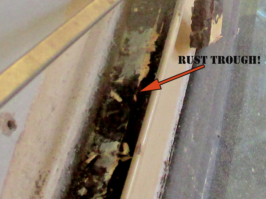
With the roof finally blocked (14 hours... ridiculous), I jumped in on the assault on my rusty gutters. A flat blade screwdriver, a hammer and some tapping soon had chunks of decrepit caulk flying all over the place. The grey areas are where factory primer was still in place, the brown, well that's rust baby. Step one was to wire wheel the area, but all this did was sort of polish the rust but did make the caulking remnants fly. My goal at this point was to grind off the rust so I could get down to clean sheet metal once again and redo the paint and sealer.
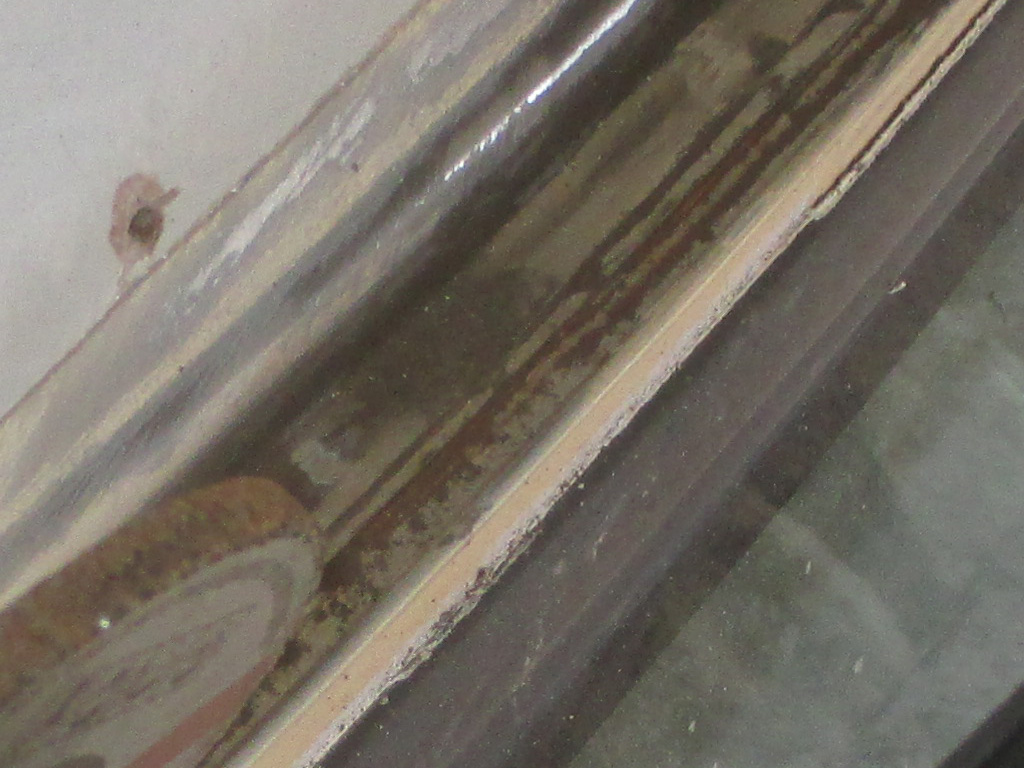
I studied the situation and selected my air grinder equipped with a wide grinding stone for my first salvo against the rust monster. I set my regulator for 60 psi and was able to control the speed much better and kept moving the tool along the channel to help keep heat down. It took awhile, but eventually I got down to clean shiny sheet metal once again. Since this won't be seen, I'll leave it rough for the primer to stick to. Then some seam sealer, more primer and a finish coat. The hardest part of the whole operation though is removing the rust. Every place there was a spot weld I now had a small circle of rust that the big grinder couldn't get into.
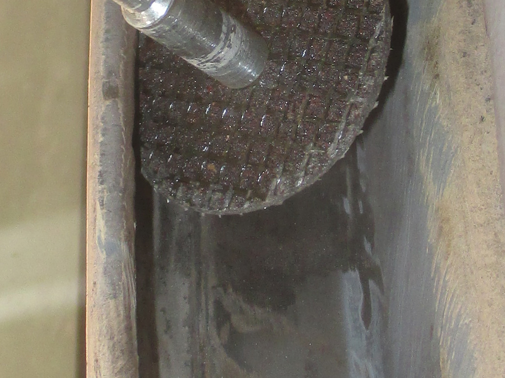
For tight spots like this, my Dremel is the "go to" tool. The only problem was, mine was wearing out. At one point smoke was coming out of the little vents, so I tried cooling it down with some compressed air. Each time I used the tool, I had a shorter and shorter usage time before the smoke. Finally there was a "PUFF" sound and smoke poured out of the vents. Scratch one Dremel tool.
But all was not lost... I have two other Dremel tools, they just need new switches (previously purchased but never installed), and I should be back on task in short order. I tried my next newest tool first. I used it for 5 minutes and it too crapped out. If I tapped it, it would run for a second or two. It's probably a short or something (I might even be able to swap motors between two), but I really don't have time to be fooling with this!
In desperation, I turned to my first Dremel and replace its switch. Nope. Dead as a coffin nail. Thanks a bunch Murphy. Not wanting to make a special trip for a new tool and loose even more time, I focused on the bigger areas where I could use the air grinder.
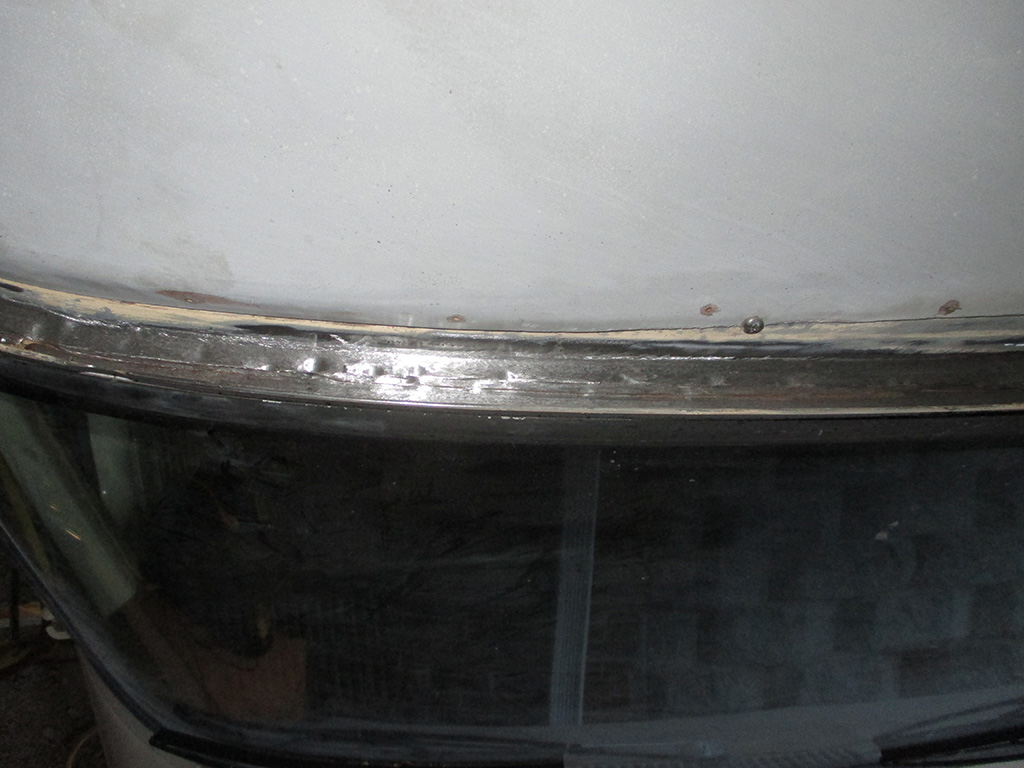
By cobbling things together (like using a Dremel attachment in my 1/2 inch DeWalt drill), I was able to at least keep some momentum going. But the big drill is far too large and cumbersome to use for very long before fatigue (or grinding wheel breakage), sets in and you have to stop and rest for a bit. I persevered and in the end, I finished what I hope is the hard part, the area over the windshield. At least working on the side and back I can get my ladder right up against the van so I don't have to reach so far. More than once the ladder started getting tippy and I had to re-set it and start over.
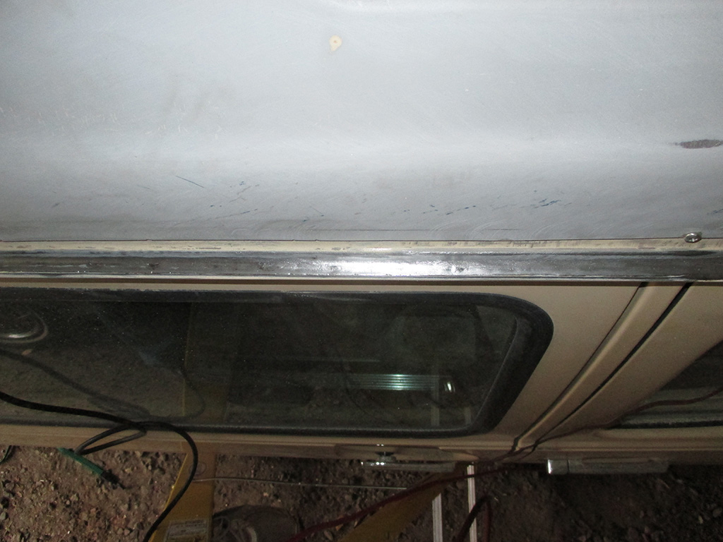
As I moved away from the front corner, the rust began to peter out. The caulk was attached more solidly to the surface (making it harder to remove) and primer still existed beneath it. I found a narrow wire wheel and attacked the gutter channel with renewed gusto. I used my electric drill with a second handle attached for stability. I like being able to reverse direction (makes the wires really dig in again), when the wires of the brush take a set in one direction, a downside to using my die grinder.
This meant I could make up for the time lost on the front corner which had heavy corrosion. I had to use a cone shaped stone to grind out a few deep cavities of rust, but thankfully no holes. By comparison, the side got pretty cleaned out with just the wire wheel. I just have to touch up the outer edges with the Dremel. Once I purchase another one that is.
In a project like this, there's always an opportunity to become the neighborhood mad inventor. I needed a way to remove moisture from my air line and make it accessible to my rooftop project. I took a hole saw to the stepladder repurposed some scraps of copper wire and presto... a ladder-top air hookup.
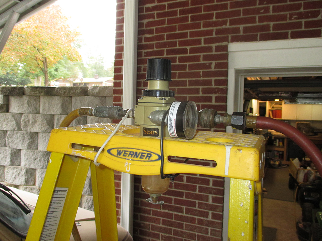
WATER TRAP
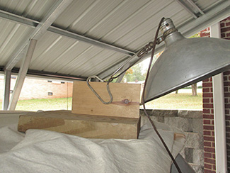
LIGHT BASE
Ever have one of those ubiquitous clamp on utility lamps and nowhere handy to clip it onto? I screwed two scraps of wood together as shown and created an instant platform for the light. You could also hang some string over it and loop each end over a tubular work light too, like the one I used to own. I've clamped these to welding magnets too, when the surface I was working on was metal.
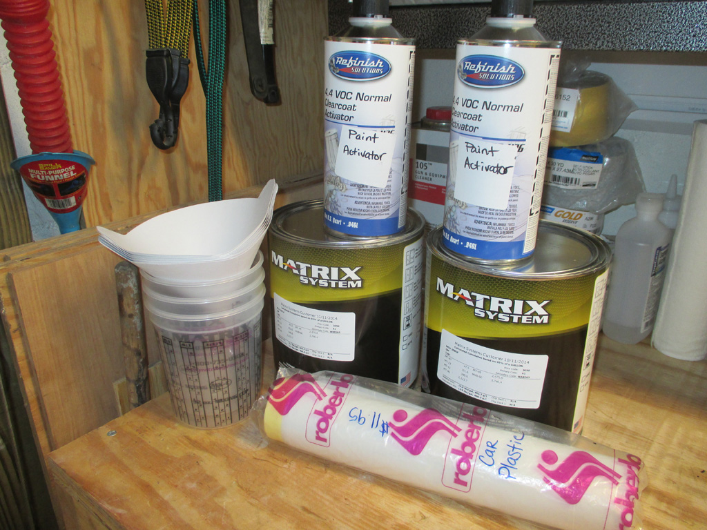
Last Friday I made another trip to my friendly neighborhood paintshop and ordered 2 gallons of paint. I'd ordered a pint previously to refurbish the battery tray, so I had the original label for them to duplicate the formula. I now have enough to do not only the roof, but the rest of the van as well. By getting both gallons at once, a match is assured as they even "cocktailed" the paint so both are identical.
This little extravegance lightened my bank account to the tune of $375 for the paint, activator and masking film. I have the epoxy primer already, so now all I need is time. Due to my own procrastination I am now running a race against time so I can paint while the weather is still suitable.
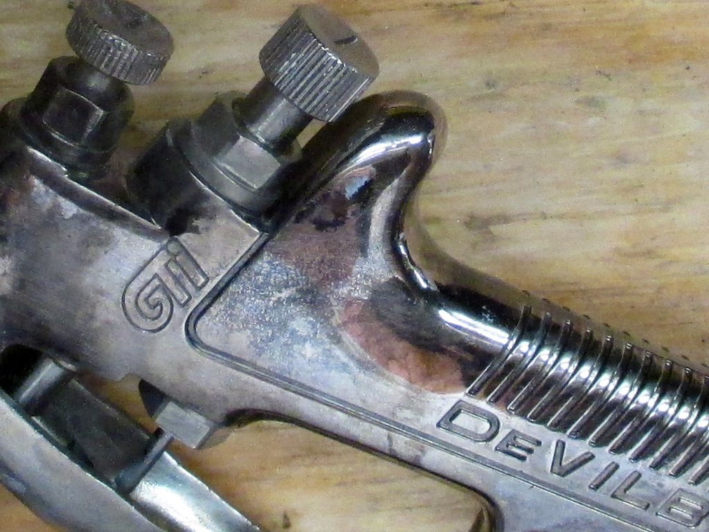
Several months prior to this, I'd purchases a DeVilbiss GTI-620 spray gun for $150 bucks off flea-bay. I spent some time doing research on DeVilbiss guns and settled on this as the best for my purposes. From what I've read I can change this to a "Plus" gun by swapping some parts, but the plus gun uses more air and creates a much larger cloud of paint. Since my air compressor is marginal anyway (at providing the needed CFM for the gun), I definitely didn't need a gun that used even more air.
The gun came with a 1.4 fluid tip (I'll have to pick up the missing 1.3 and 1.5 tips at some future date), air pressure regulator, stainless steel paint cup and 3M disposable cup adapter.
Another $25 netted me a DeKups demo kit with disposable liners, an adapter for the gun, the liner holder and caps and filters. I purchased a 1.5 fluid tip off fleece-bay and got hosed... the tip had a flat spot which will upset the airflow in the gun. Lesson learned. Next time pony up the cash for a new fluid tip (although the one I bought was listed as such) and not try and cheap this together. In my own defense after buying the paint, a $40 fluid tip was too tempting to pass up.
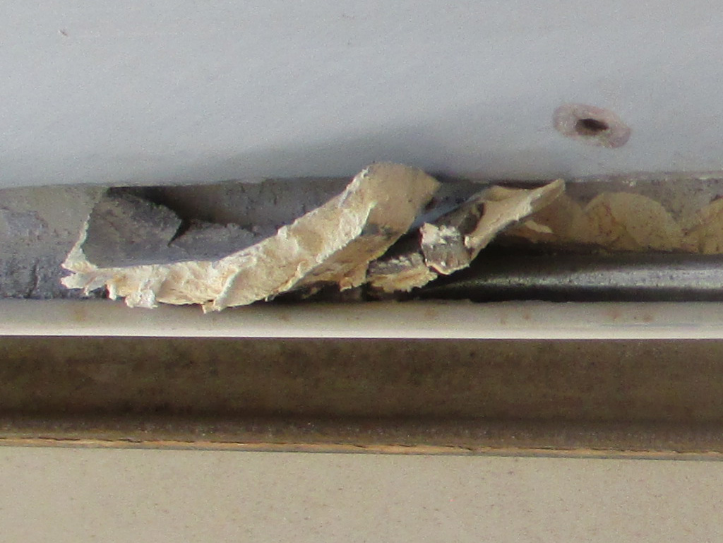
I've discovered that I can complete tasks very quickly in my mind. Back in the real world? I lost track of how many days I spent preparing the roof for primer. Using a long narrow screwdriver, I was able to chip, pry up and remove the bulk of the ancient caulk that was still tenaciously clinging to the gutters of the van.
Although a bear to remove, most sections had cracked and water had seeped underneath the caulk. This caused rust. I hate rust! So... If I'm going to primer the patch where I removed the windows, I really should shoot the whole roof where several patches of factory primer were already exposed. And then... since I'm already up there... I might as well do the gutters and make my van weather tight once more. That friends is what's known as a snowball!
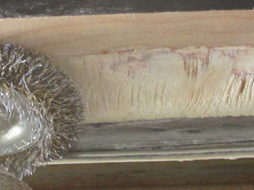
With the bulk of the caulking removed, cleanup of the gutters began with wire wheels... quite a few of them in fact. To remove as much of the caulk residue as possible, I had to tip the wire wheel dangerously close to the fiberglass roof, scratching it despite being as careful as I could.
I grabbed a scrap of luan plywood, stuck it to the roof with black electrical tape (later switching to the existing screws for better attachment) and got back to business. With this in place I could really focus on material removal without worrying about the top. The third and final step was to Dremel the rust pits and caulk remnants using a metal cut off wheel.
I really got the caulk smoking with the Dremel tool. The stuff really stinks too. I figure I went through about a dozen or so of the "quick release" metal cutting disks, later switching to stone wheels, fiberglass reinforced wheels (or whatever else was left in my tool box by that point), anything that would let me reach down in there.
Friday October 17, 2014.
This was my "drop dead" date to finish all the wire-wheeling, grinding etc., so the next day the primer could be laid down. I didn't quite make it. Saturday morning I was still at it when my FIL arrived with some additional equipment we might need.
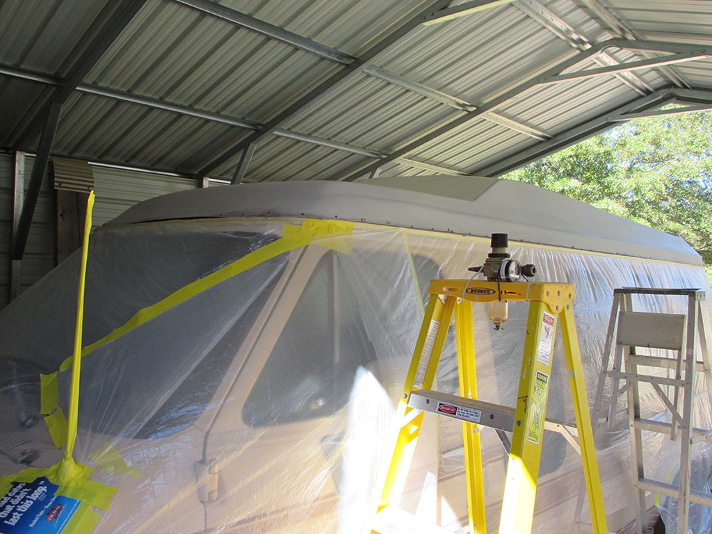
Front
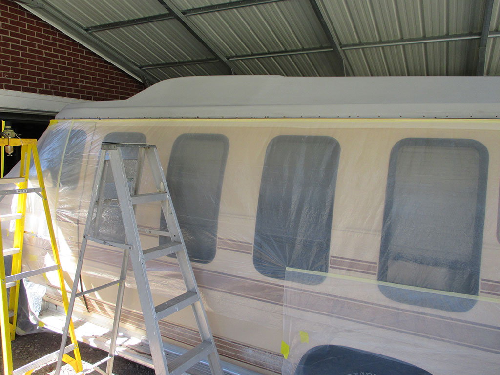
Side
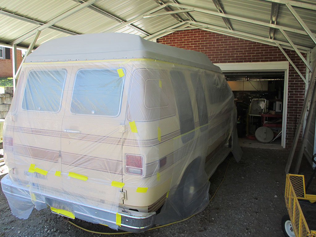
Back
By the time we called it quits Saturday the sun was setting and the temps were dropping. So... we decided to mask 'er off and wait until the next day to lay down the paint. A roll of "Fluff & Cling" (thin masking film with masking tape built in to one edge), was easily the best $11.95 I've spent in a long time. Roll it around the vehicle, taping as you go, unfold the film which clings to the vehicle, tape down any loose edges. Done.
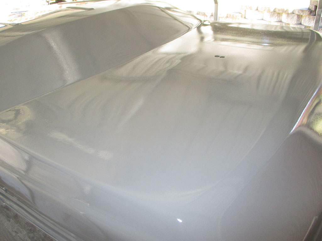
After a leisurely Sunday breakfast, it was time for final preparations. This amounted to wiping the whole roof down (gutters and all) with wax and silicone remover so the paint would have the cleanest surface possible before painting. For the first time, I became familiar with a tack cloth which did a really good job of gathering up the lint from the paper towels I used earlier.
I began painting over the driver's side windshield, working my way down the driver's side towards the rear of the van. I went around the back and up the passenger side to finish over the windshield, overlapping where I began. By the time I took this shot, I'd laid down two coats of primer, the only flaw two small runs in the paint on the drivers side near the gutter. I moved the ladder 14 times with two trips each time per coat. As near as I can figure, I went up and down the damned thing about 60 times at the very least.
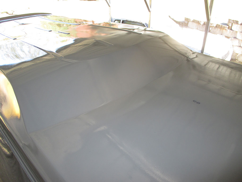
A more direct shot of the area which precipitated this whole little adventure, as well as the rear roof panel. Both windows are history, glassed in by yours truly. If I look at the passenger side of the repair, I can see a couple of imperfections. Since I'm using the stock color, which is light to begin with, they may not show that much. However, the perfectionist in me is already plotting how I might touch them up to make them less visible. You'll never see them unless you're 8 feet tall, but I know they're there.
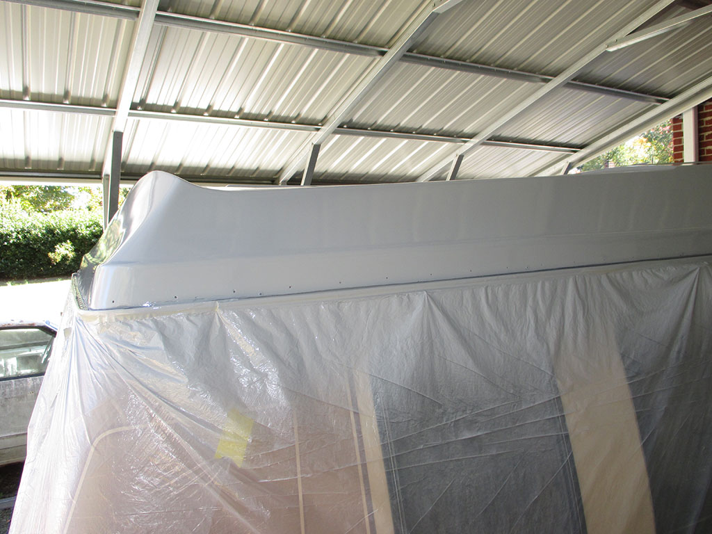
I think I may have one of the only vans around with a duck-tail spoiler in the back. If you click to zoom, you can see the reflection in the rear as well as the side of the roof from this angle. And just think... I get to do this all over again with the color coat, probably not until spring though. I'll have all I can do to complete the next step, seam sealer for the gutters.
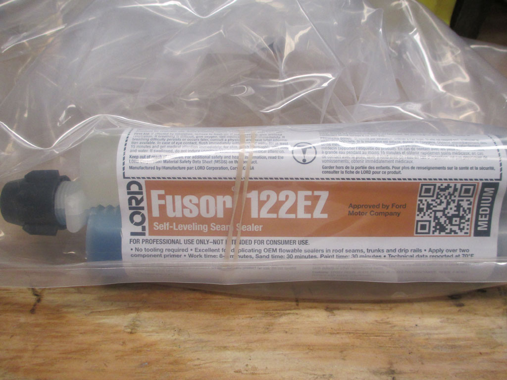
I did quite a bit of research for the best seam sealer to use on my freshly refurbished drip rails. From everything I read, two things became readily apparent. 1. You get what you pay for. 2. A two-part sealer formula is superior to a single tube formula. I was exceedingly displeased with the performance of the 3M brush-able seam sealer I used on my Monte SS. It cracked all over the place and basically I'm going to have to wire-wheel all of it off and start over! I DO NOT need to run into the same issues on my van.
The downside to this is the twin tube seam sealer also requires a special caulking gun to dispense the material. My FIL has one, so I'm okay on that score. I've never used self leveling seam sealer before, but again from what I've read this is what I need to duplicate the factory finish. I've also got a much newer (and I'm willing to bet superior), formula compared to the original. Once I complete this step it'll be time for winter hibernation once again, as I don't think the weather will cooperate long enough to squeeze a top coat in.
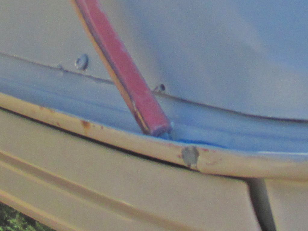
Saturday was a mixed bag progress wise. Indian summer was in full swing with temperatures in the upper 70's with bright sunshine. Before "Fusor-ing" up the drip rails we sanded the runs out of the primer with some 320 grit sandpaper followed up by 400 grit using a mini sanding block. I felt better once this little task was out of the way.
The next step was to take some pieces of a Scotchbrite scuff pad and dull the primer so the seam sealer would have a better surface to adhere to. Although the twin tubes were labeled "Medium" the stuff began setting up before I got up on the ladder. We had to replace the special mixing nozzle and trim it for a wide flow and then hustle my butt up the ladder.
The hardest part to reach throughout the whole process has been the drip rail over the windshield. So this is where I started, opening the hood to give myself a place to stand worked well for this step. This is the first time I've ever used this stuff and I tried to replicate what the factory had done. The drip rail over the windshield is also deeper than anywhere else on the van. Needless to say, I used the stuff up too quickly and ran out.
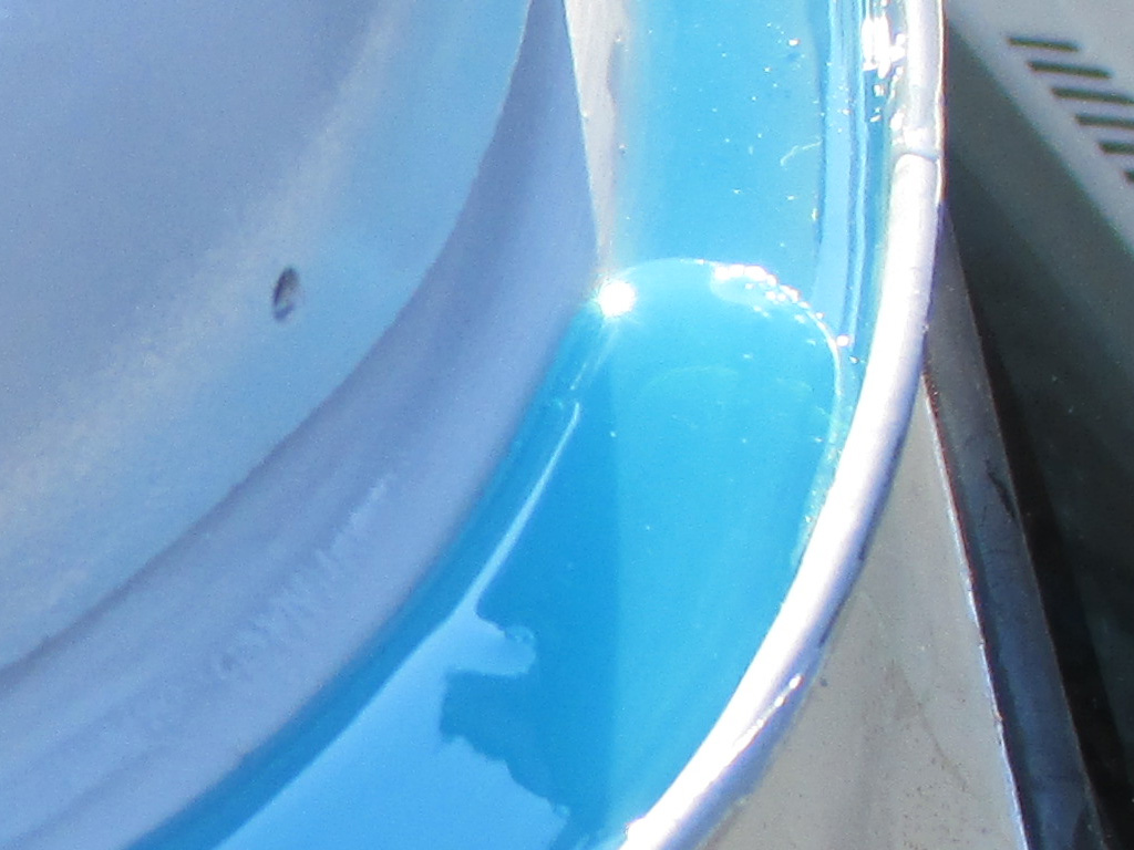
This stuff is pretty amazing to watch as it flows out and fills the target area. I quickly learned I had to squeeze the trigger on the gun and move the tip slowly enough for the drip rail to be filled to the proper height. Again, I was trying to duplicate what the factory had done, no real reason why other than that's the way it was done originally. The two part mixture comes out of the tube a nice pretty blue color, but is sandable and paintable.
The next time I use this stuff I have to make sure I've got a good supply of paper towels nearby. Each time I raised the tube out of the drip rail so I could move the ladder I ended up with strings of this stuff hanging off the tip of the tubes. If I did this kind of thing on a regular basis, I'd construct some sort of scaffold so I could walk around the van continuously, saving myself all the up and down trips.
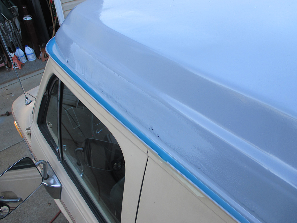
Having taped over the drip rail cut-outs so the sealer wouldn't run all over the place, I decided I would focus on the front 1/4 of the van and at least have that part done as I began reaching the end of the twin tubes. Although disappointing, I will order more of this stuff bright and early Monday morning so I can get another batch shipped to me ASAP. Once I get this completed it's on to working on the epoxy primer with some 600 grit paper in preparation for the top coat.
Electronics
Front Speakers & Wiring
January 2013
With other projects temporarily on the back burner, I dove headfirst into my stereo upgrade project. Far from being my first rodeo (stereo wise), I nonetheless got a little bogged down trying to decipher the wiring. Since sorting things out on my workbench is much easier than in the vehicle, I grabbed some test speakers, the train transformer I use as a power source and got down to business. The OEM head unit I scored off flea-bay works fine, I just have to replace the little "stereo" lamp before mounting it in my van. The next step will be wiring in the EQ and testing out its functions before mounting it as well.
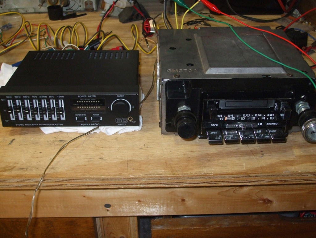
BENCH TEST
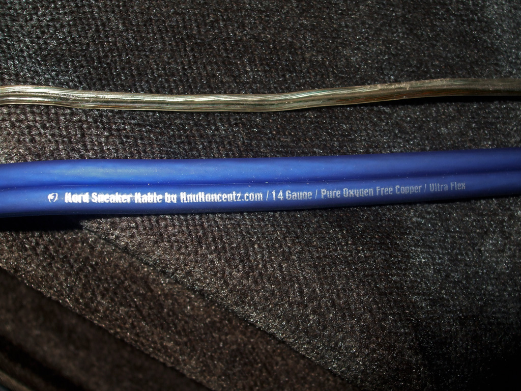
UPGRADE
The speaker wires have now been upgraded to 14 gauge (from the woefully inadequate 22 gauge speaker wire previously installed), that have 189 super fine strands instead of several thicker strands as before. I was stymied because the EQ has 4 speaker level inputs (wires), while the radio itself has 8 speaker output wires! I was in a quandry, trying to make 8 go into 4 electronically. Once I was able to determine that the radio only has a front/rear fader (same as the EQ), the little light bulb came on. I'll pair the two fronts together and the two rears together. Hopefully I can use the EQ the same way the original radio was wired. Time will tell of course but "confidence is high" at this point.
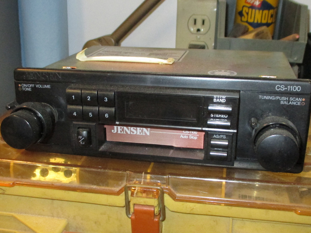
Here's what was in my van the day I drove it home. All I could get out of it was a blast of static (perhaps the complete lack of an antenna mast might have something to do with this), and only one speaker worked. The drive home was a quiet one. I don't know if this unit works or not, but it's newer than the van and incorporates a built in clock.
The only problem with that is... I already have a vintage correct digital clock in the overhead console. Looks kind of silly (not to mention trying to synchronize the two), having two clocks in the same vehicle. So, all that taken into account, I decided I needed a head unit that was from the era. With my Pioneer Super Tuner sidelined with a broken tuner shaft, I went OEM and installed what might have come in a GM sourced vehicle back in the day.
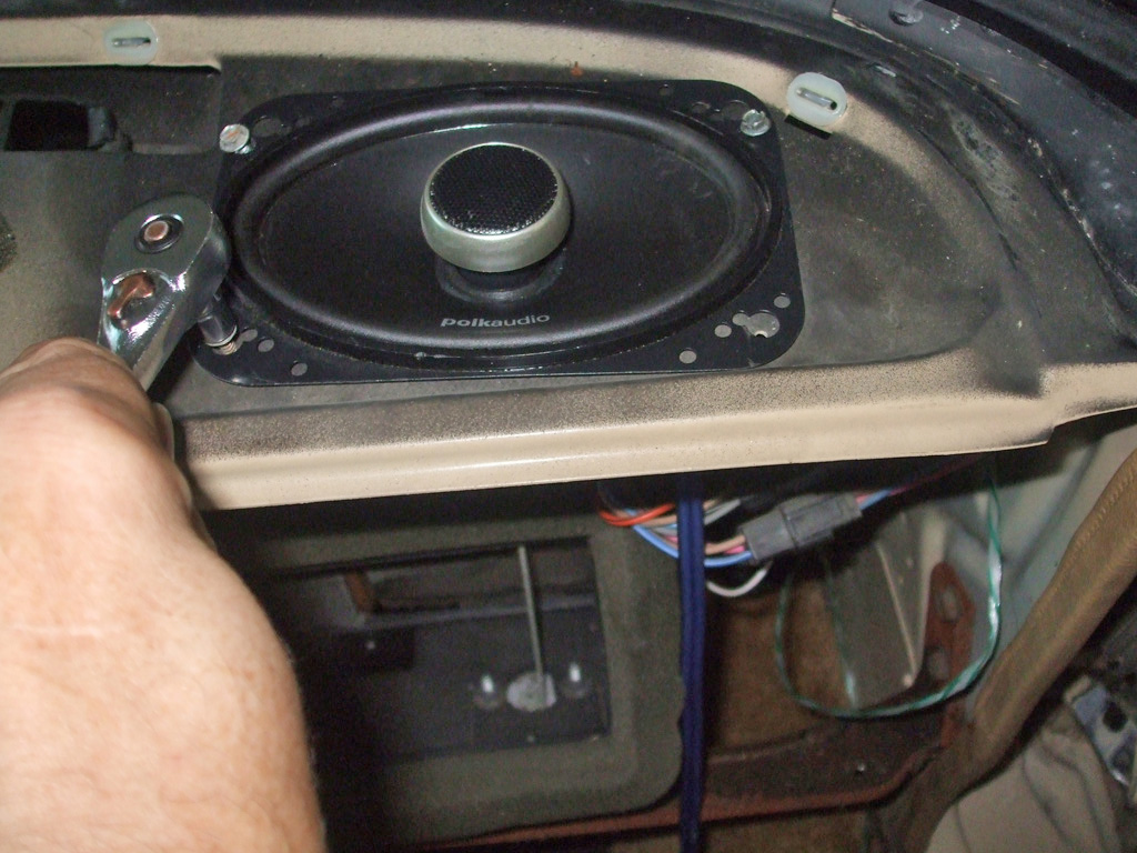
Just as full dark was enveloping both me and my van, I finally got one of the front speakers installed. I went with Polk Audio this time out due to the extreme nature of what you have to go through just to get to these babies. Even though I took the speaker with me to the local electronic supply house, they still mismatched the larger of the two terminals. Next time I'll double check the fit before I leave the store!
Being as it was Sunday (not to mention that I'd already crimped the terminals onto my new premium speaker wires), I grabbed some pliers and pinched the solderless connector until it mated up nice and tight with the bayonet connector on the speaker. The stuff you have to go through sometimes... sheesh!
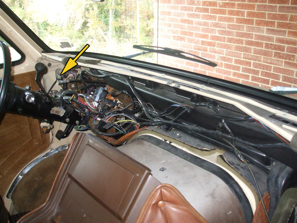
My new speaker wires will run up through the windshield pillar and back along the inner roof rails like the factory wiring was originally run. The arrow illustrates not only the access hole I used, but the factory wiring I used to pull in the nylon string I plan on using as a "pull line" to run my new speaker wires to the rear of the van.
However, before I could begin to run my wires (not to mention installing my new speakers), I had to get the dashboard out of my way. What a job that was. This baby put up a real fight. In the end (just as the sun was setting) I finally managed to pull the blasted thing free so I could move on to the next step.
Once I started digging into my van's wiring, I found it to be in a sad state of affairs. The PO must've gotten a truckload of 24 gauge speaker wire cheap (or maybe free), since he used the damned stuff everywhere. Overhead aircraft lights? 24 gauge speaker wire. Rear cigarette lighters? 24 gauge speaker wire. Rear speakers? 24 gauge speaker wire. I wondered how the hell he kept from confusing everything, until I noticed the 12 volt power wires had knots tied in them every 2 feet or so! So, I unceremoniously ripped out every last inch of it. The van not burning down to the ground before this, was more of a miricle of low voltage and infrequent use than anything else.
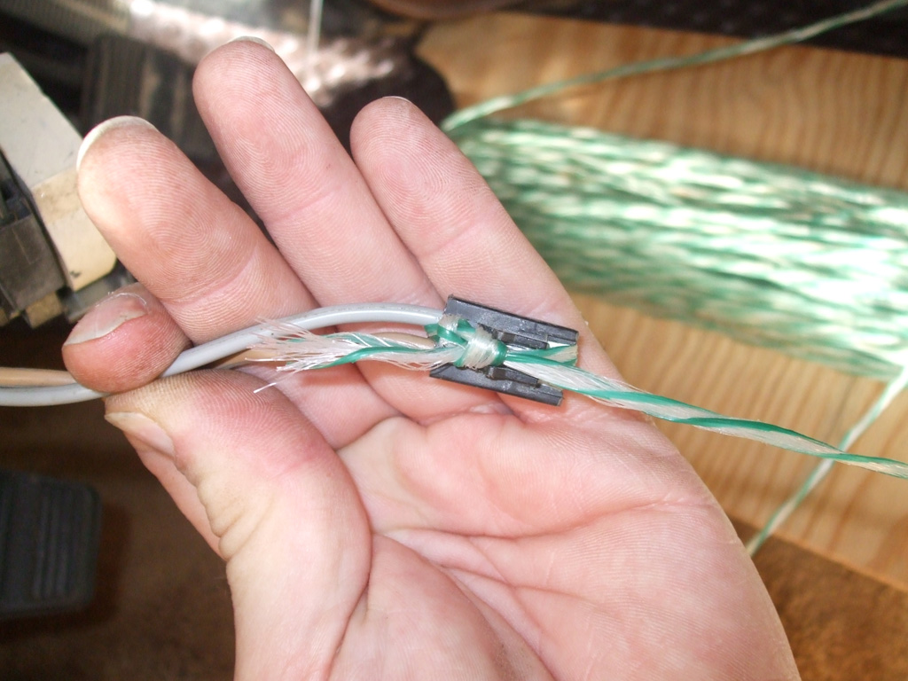
By unplugging a twin wire connector already running up the windshield pillar, I had a convenient way to run my pull line up through the windshield pillar and into the roof rail over the driver's side door. I simply tied the nylon pull-line string to it (followed by a generous wrapping of black electrical tape for extra insurance), and presto! Quicker 'N you can say Jack Robinson I was in business.
Once the string came through I untied it, pulled through several feet of pull line, then re-attached the connector and (using the string and some more black electrical tape) pulled the factory wiring back where I got it from. It probably took me longer to type this than it did to actually perform this operation.
The passenger side (which I'd completed first) was tougher, since there was no facory wiring on that side. Fortunately, someone at somepoint had cut a nice jagged rectangular hole in the panel over the passenger side door, that I made careful use of. I ran a length of fishing tape (more commonly used in home improvement situations), down through the pillar, tied my string to it and pulled the line back up through the windshield post and out through the hole. I then used some of the 24 gauge speaker wire that had been feeding the rear speakers to pull a second shorter pull line back over the slider to the rear speaker location. Running the rear speaker wiring was a real test of my ingenuity, so I elected to wire those up first. The fronts were duck soup in comparison.
Once I decided to eliminate the overhead console speakers, I was faced with the task of installing speakers in the factory dashboard holes. I won an auction for a pair of Polk Audio 4x6 coaxial speakers to install in the factory location. Rated at 40W RMS (120W peak) each, these 4 ohm speakers should work nicely with the factory head unit and vintage Realistic equalizer I have waiting in the wings. The downside? I had to pull the entire dashboard out to gain access! The upside? The factory provided four pre-stamped screw holes for each speaker. Rather important considering I couldn't even begin to get my drill in there... no way, no how.
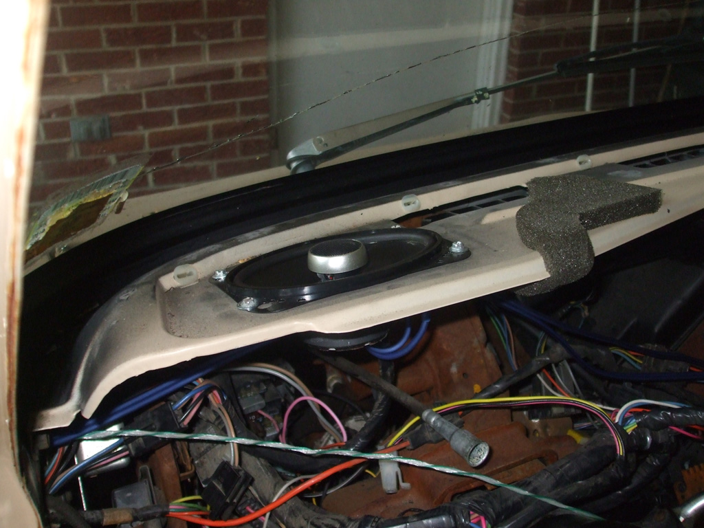
LEFT TOP
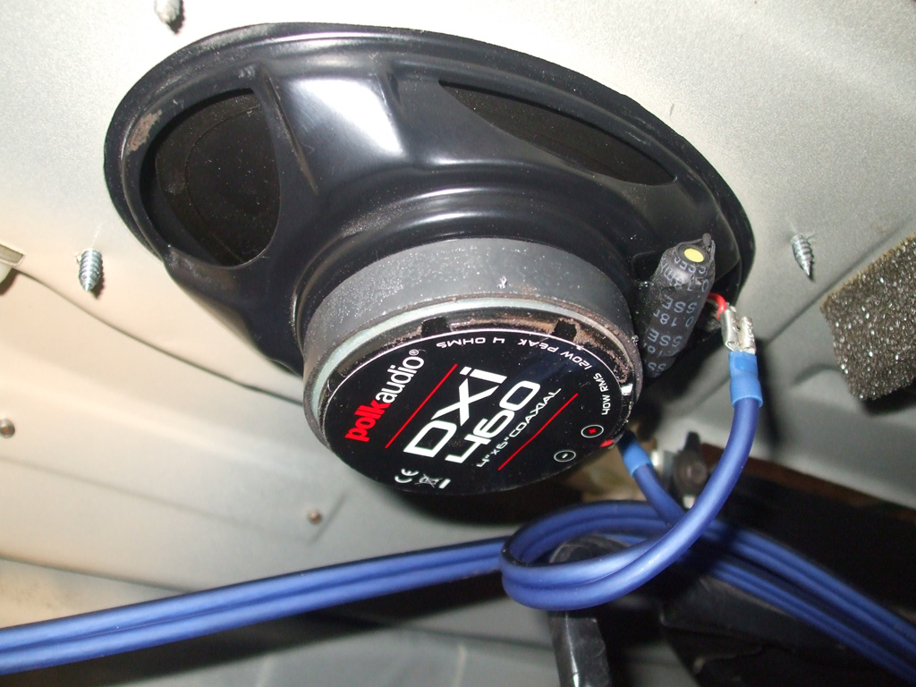
LEFT BOTTOM
However, if what I researched on the internet is correct, a 4 ohm speaker is only used with an all tube configuration radio. If your radio is a hybrid (part tube, part transistor) or all transistor (1962 or later) it needs an 8 - 10 ohm speaker. Crap! Since the equalizer I bought is switchable between 4-8 ohms (with speaker level inputs), I'm counting on it to save my bacon. I also have a separate amp & subwoofer (salvaged from my Monte LS), but will not be adding them at this point. The attraction of this particular EQ was twofold, improved sound and a 1/8 stereo input jack for my iPod!
Dashboard Wiring
You know... I had a feeling I'd find some of these dastardly things in my van. Officially called the "3M Scotchlok 558 Self stripping Electrical Connector" it is the bane of hot rodders, vanners and gearheads everywhere. It looks like a neat idea for tapping into an existing power source. In point of fact though it causes more problems than it solves. If I need to tap into a line, I use old fashioned solder, liquid electrical tape and black electrical tape to make such a union.
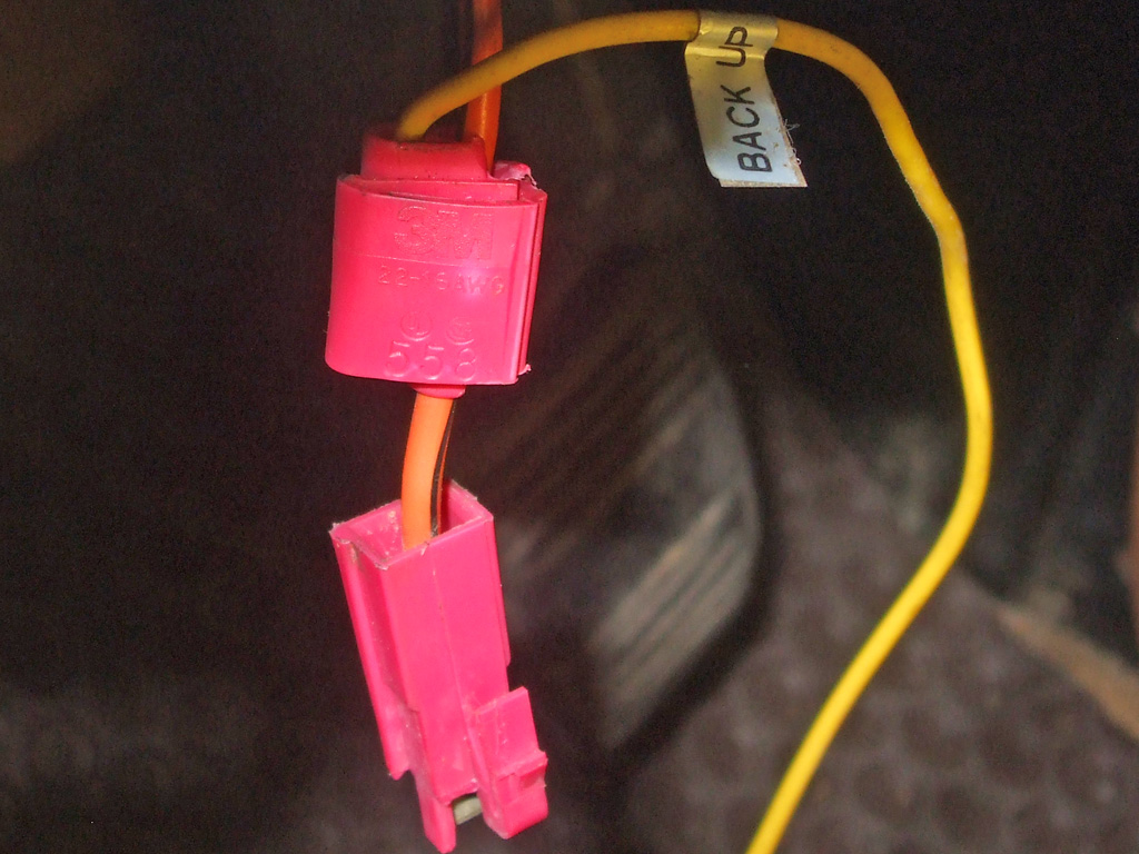
3M Line Tap
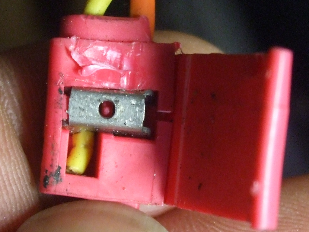
Inside
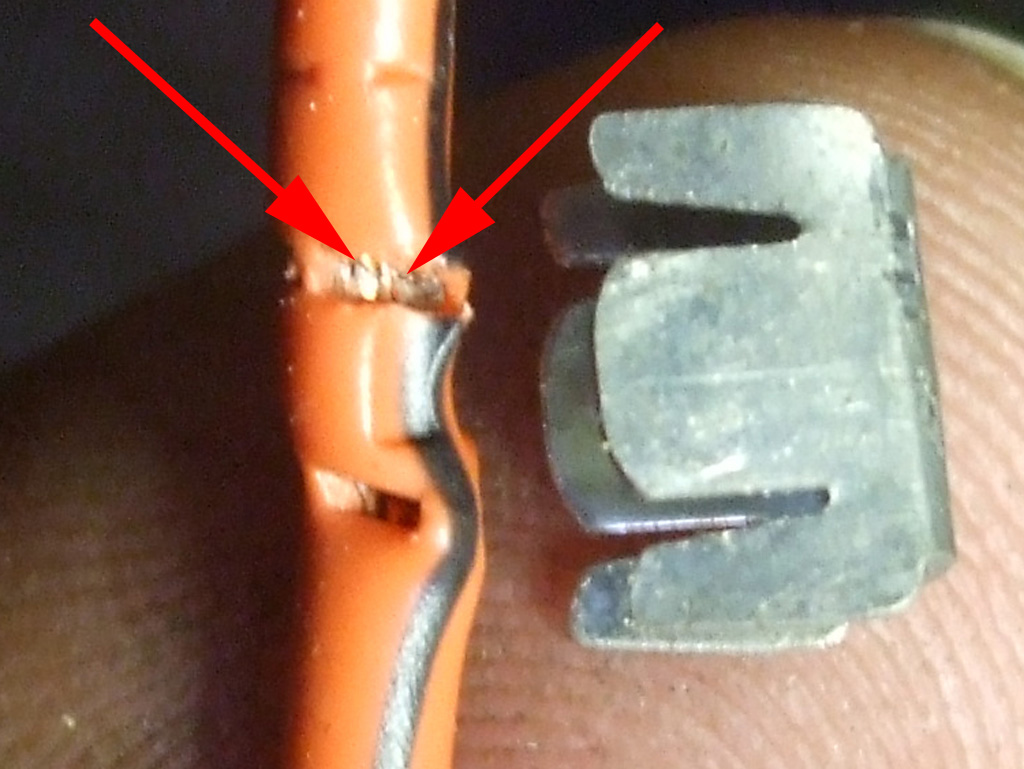
Cut Wires
It's the "self stripping" aspect that is the problem. You simply cannot use this connector without damaging the wire. Click on "Cut Strands" for a close up showing at least two strands of copper wire completely severed. When you find one of these underneath your vehicle, where it's been exposed to the elements, corrosion quickly forms and travels in both directions of the host wire. Do not use these on your vehicle. Like most shortcuts, they're just not worth it in the end.
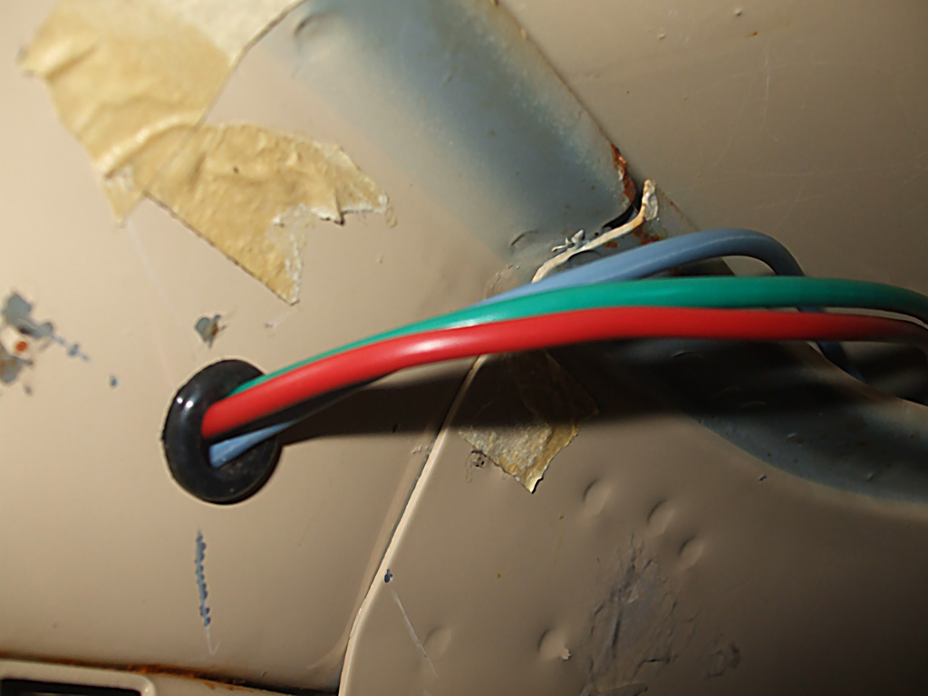
The PO had completely bypassed the four switches in the original overhead console, leaving me with no frame of reference for how things had been. I did know two things. One I wanted wires that would carry the load. To that end I purchased a couple of spools of 12 gauge primary wire in different colors. Two, I wanted as short a run as possible to keep resistance to a minimum. To that end I ran my three new wires up the windshield post (pull line really earned its keep) and out through a hole I drilled where it will not be seen when the console is installed. A rubber grommet to prevent chafing and I was good to go.
I figured it would never be as easy as it was right now, so I tried my best to think and plan ahead as to what I wanted to power and where the leads needed to be. The overhead console I purchased had three sets of double switches. I'd previously purchased a single gang of four fused switches (the fuses being hidden behind a cool little flip-up door above the switches) so I'll be using the ganged switches instead.
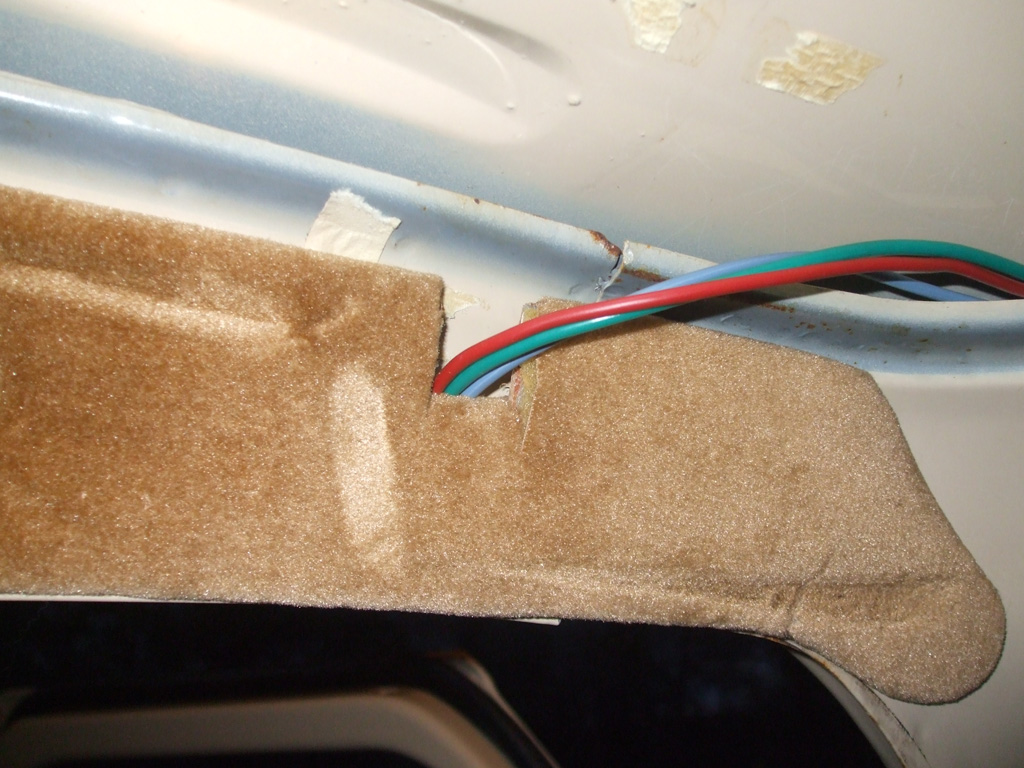
With the new power feed lines in place and cut to length at the fuse block (and the 3M connector resting peacefully in the trash can), I decided to cut a notch in the side panel to relieve stress on the wires. The wear marks seen here are from where the original overhead console and headliner butted up against the side panel. Based on that (and the fact that the new console comes out and down just about the same amount), the notch will never be seen anyway. Nonetheless, I carefully cut the fabric, notched the luan plywood, then folded the fabric back over the wood as protection against chafing the wires.
As it stands now, the red will feed the switch panel, the green the CB and clock and the blue the lighted sunvisors. The only way I can think the original was wired would have been to run wires back through the side roof rail area, then back forward over the headliner. I think my method is neater and more electrically efficient. As always though, the proof of the pudding is in the eating. I'll have to wire everything up before I can call this a success. But the wires needed to be run now, before the dash gets reinstalled.
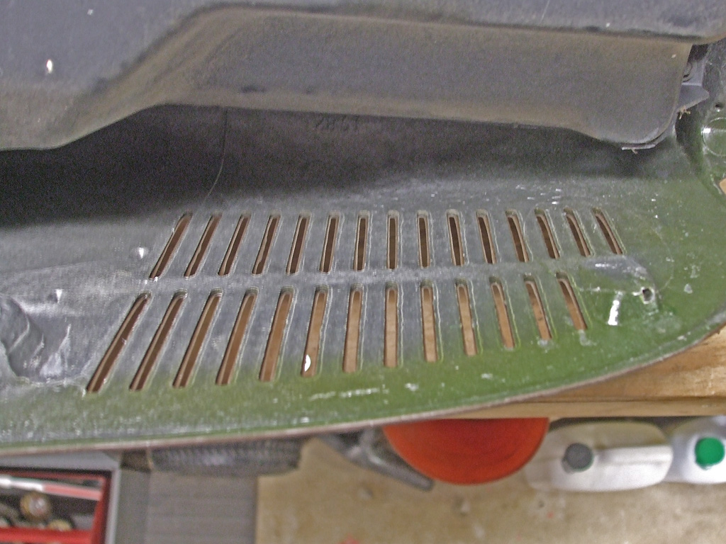
Ah yes, let us turn our attention to the dashboard, shall we? Back before I discovered speakers in the original overhead console, I bought some speaker cloth to mount beneath the factory slits in the dashboard. Once I changed my master plan (and then changed it back again), I had to find where I had squirreled away the speaker cloth several months ago. Took me about an hour and a half (not including an impromptu bowel movement), and I was ready to trim and install the cloth.
My initial reason was to keep dirt, dust and other fine detrius out of my new high-zoot speakers. It also prevents unscrupulous types from looking in the windshield and going "ohhhh look at those". This of course meant I had to find an adhesive that would stand up to the harsh environment of an automotive interior. My go-to in situations like this is the tried and true silicone method.
First I measured the overall area I wanted to cover. In my case it was 8 inches by 7 inches which I cut from the bolt of cloth I had on hand. I placed the "rough cut" cloth over the opening, made sure I had enough overlap to lay down a bead of silicone and placed trimming chalk marks on the cloth. Once I was satisfied with the fitment of the cloth, it was time to lay down a nice, thin bead of clear silicone.
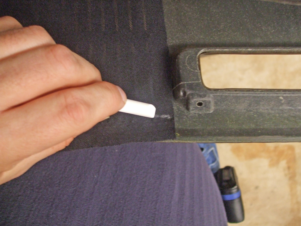
Marking Cloth
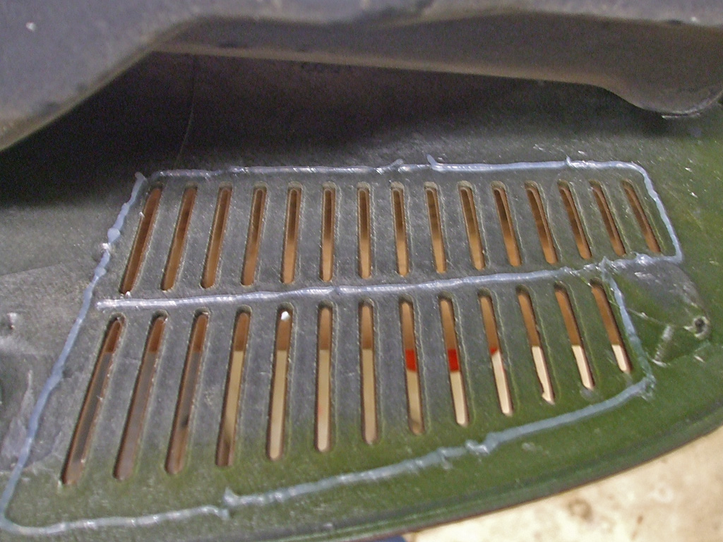
Apply Silicone
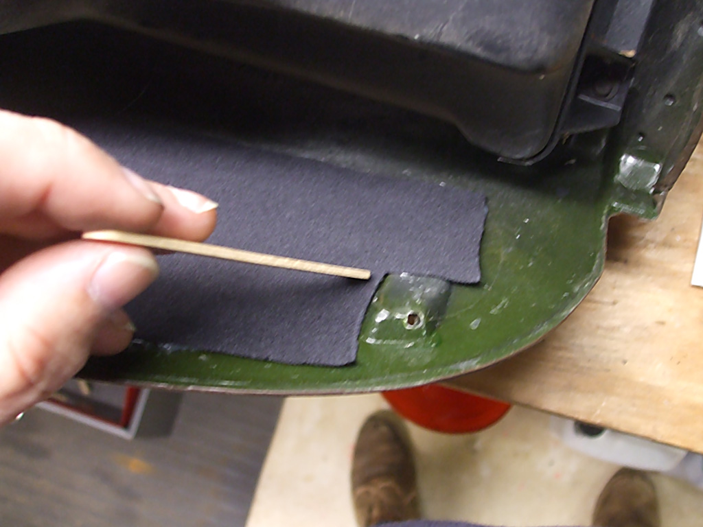
Smooth Cloth
With the silicone in place, I carefully laid the cloth down in position and began smoothing it out with a craft stick. After a while, it became apparent I would need more pressure, so I reverted back to the old finger method. This gave me more control and I could feel the silicone begin to saturate the cloth meaning it was time to move on. I let it cure for 24 hours and was satisfied with the results.
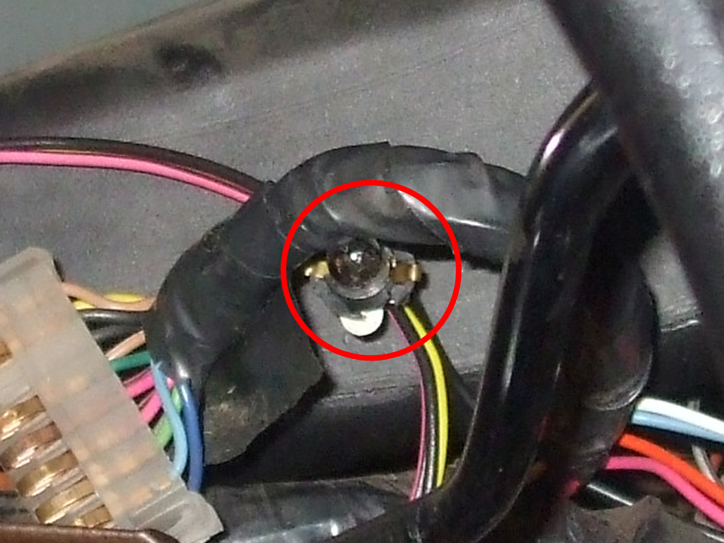
During the re-installation process, I discovered something. That something was this... I don't know how the hell I got the dashboard out of there in the first place! Granted I was being careful of the new speakers, but no matter what I did the damned thing just said NOPE--AIN'T GOING IN. So, I removed the two nuts holding the steering column to the bottom of the dash and leaned on it to gain just enough space to get the dash back in place without damaging anything.
In the process, I discovered why I could never see the heating/ac controls at night. The bulb was burned out. This led me to examine the rest of the instrument panel bulbs and sure enough, I found 3 more burned out bulbs. That's just peachy! So, before I can reattach the electrical connectors to the heating controls and re-install those (not to mention the instrument panel), I need to get some bulbs.
While I'm At It...
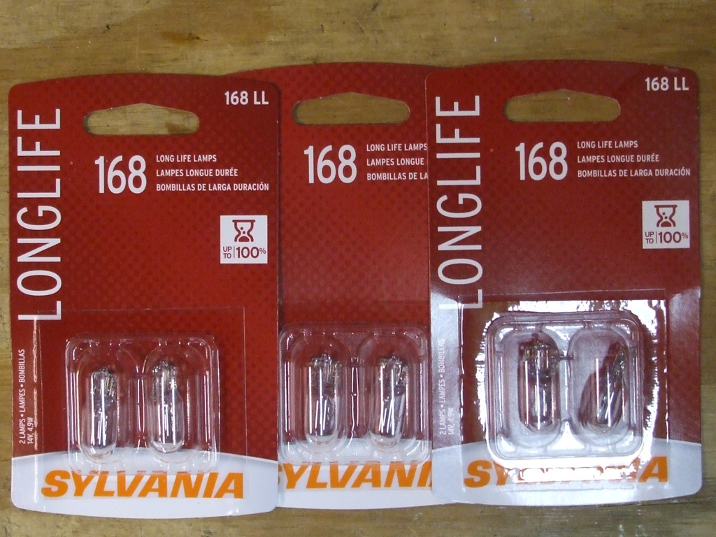
Nothing gets me in trouble quicker (or slows down a project better), than the "as long as I'm at it, I may as well..." line of thinking. Replacing the bulbs will never be as easy as it is right now, with everything accessable. The shadows were getting long by this point anyway, so it was time to call it a night, then make a parts run the following day. A quick stop at the local parts store (and the ensuing sticker-shock), where I picked up a few packs of these babies. At $4.99 a pack, I knew why the ordinary (short life?) bulbs were sold out.
Granted the "regulars" were only a buck cheaper, but $15 smackers for 6 tiny light bulbs seems... oh I don't know... a bit excessive? But since I sure don't want to tackle this again any time soon, I bit the bullet. And I now have spares as future replacements.

When I pulled the instrument cluster to facilitate the dashboard removal project I'd noticed it was pretty grungy. Some Windex and a paper towel removed the caramelized sodapop goo, but at some point somebody had use something a lot rougher than a paper towel. Fortunately, this is a pretty easy fix if you have some patience.
Using a damp rag and some white polishing compound I worked on the lens for about 15 minutes or so. This removed the large scratches, but left the lens looking a little cloudy. I then turned to some plastic headlight polish I had in my cabinet to remove the polishing compound swirls. Presto! Gauges that will now be a whole lot easier to see, especially at night. I've used this method to refurbish the plastic lid on my turntable, the face of a plastic clock, you name it; if it's plastic it can be buffed back up to crystal clarity.
On one piece I restored, I had to start out with 1000 grit wet sandpaper (due to some very deep scratches) then up to 1500, 2000 and the compounds to bring it back up to snuff. So, don't just toss cloudy or scratched plastic in the trash, try this little trick and save yourself some money. Replacements or reproductions are not cheap.
November 2013 - Back Together
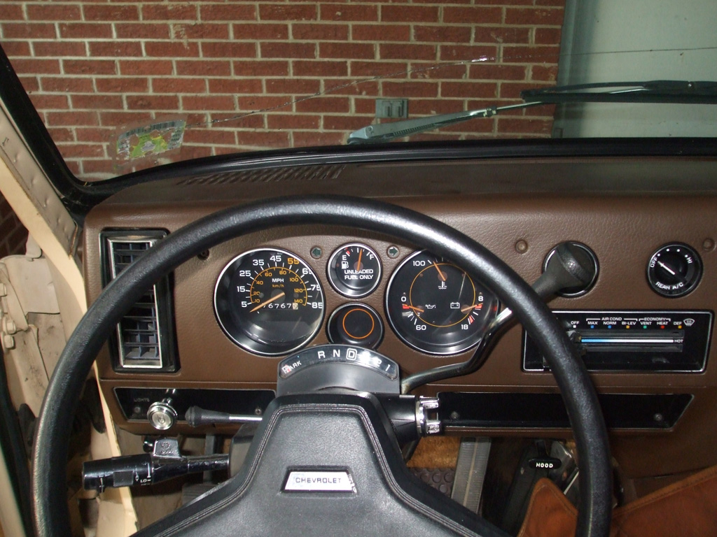
And here we are, all back together once again. Now, between the cola spots being gone, burned out bulbs having been replaced and the lens itself clear again, the difference at night should be very noticable.
The biggest hurdle to clear was the shift indicator (part of which is barbed and will cut up your forearm if you're not careful) which I wrapped in black electrical tape for the duration. The biggest revelation was dropping the steering column just a bit, which gave me the clearance to get the dash back into position.
May 2014
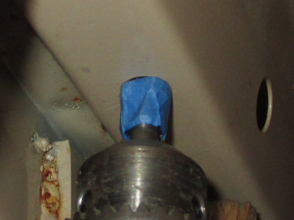
The ridiculously small gauge wires had been run behind the first side window on the passenger side, then back up to the speaker located in the right rear speaker box. I say speakerbox when in reality the box runs the length of the interior, dressing up the wheel wells and providing a base for the couch/bed.
I'm desperately trying to focus on installing new speakers and wires, but to run the wires you almost need to gut the interior. If I do that (remove the couch/bed, wheel well boxes and wall coverings), then I really need to put some insulation in place. The temptation to do the "whole nine yards" at once is very tempting; the endless loop of my "do it once and do it right" mantra playing in my head.
Anyhoo, I drilled a new hole in front of the window so I could have a direct shot at the speaker location without wasting several feet of wire in the process. I was able to gently pry the fabric covered luan plywood wall behind the side slider out enough to gain access. The driver's side though has no such access. That's where I'll probably need to take out the couch/bed so I can fish the new speaker wire behind the wall covering. Haven't quite figured that one out yet.
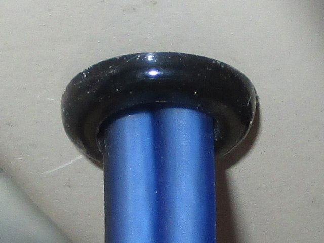
Since I'd used a stepped drill bit to make my new hole, I didn't have the sharp edges like I would with a regular bit. Nonetheless, I went ahead and protected my new wiring with a grommet as seen here. Will it really matter in the long run? Maybe not, but I've long believed in the "an ounce of prevention" rule and I've got an organizer drawer full of these things just sitting there, so why not? Cheap insurance at the very least.
I have to marvel at how these conversioin vans were literally hacked together back in the day. The hole the old wiring ran through looked like somebody made the hole with a hammer and chisel or maybe even a screwdriver. There'd be no room for my niggling perfectionism on an assembly line that's for sure. But, it's my van now and I'll be doing things my way thank you very much. This baby does bounce and sway when in motion, so I'm protecting all my upgraded wiring against chaffing and rubbing to the best of my ability.
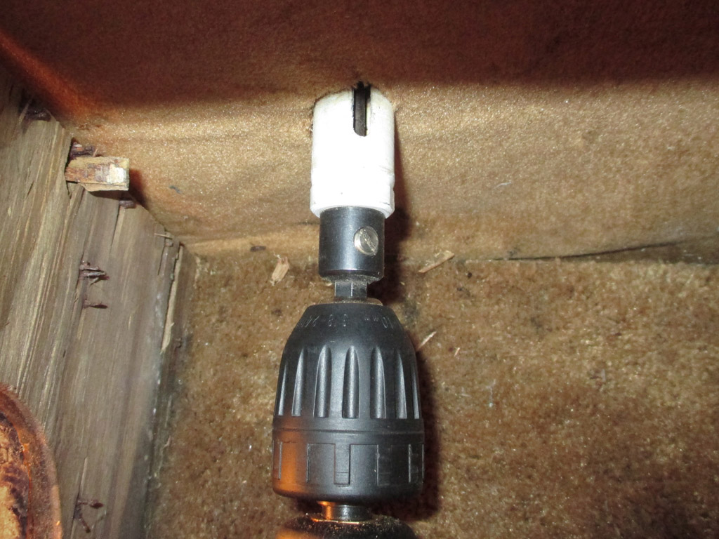
The side wall had been installed all the way down to the floor and then the wheel well box had been installed on top of that. This meant I had to drill a hole in the wall to feed my new wires through to the speaker. This was the perfect chore for my right angle drill adapter. I chucked up a 1.5 inch hole saw and drilled my hole. The hardest part of this was shining enough light through the speaker opening to see just what the hell I was doing. Other than severely splintering the wood on the back side of the luan plywood, this step went smoothly enough.
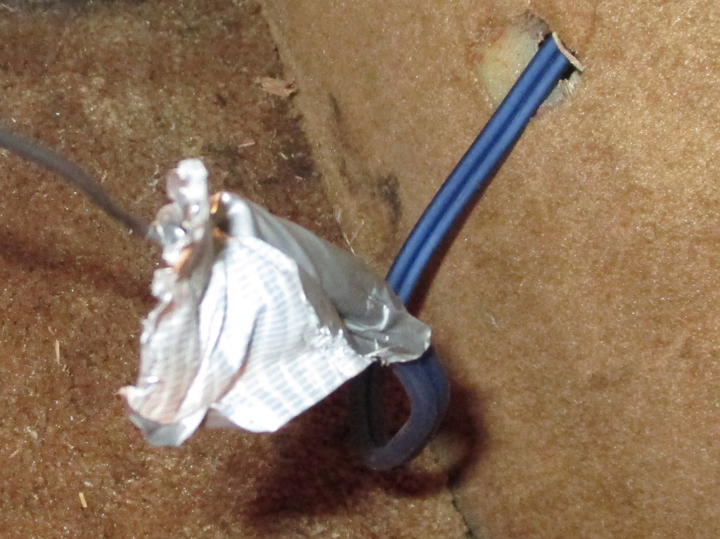
I tried putting my finger through the hole and pull the wire through but that didn't work. What I ended up doing was grabbing some wire I keep around for such things and ran it through the hole and up to where I could Ducktape the wire to my speaker wires. I pulled the whole lot back through the hole and presto, the wires for this speaker have been run. I've only got one other speaker to hook up and then I can install the head unit, the equalizer and the antenna.
The antenna will be a project in itself, since I will need to drill a hole in the firewall to run the antenna cable to the radio. The spots where I have access, would pass the cable through too far away from the radio and the spot convenient to reach the radio would require removing the dashboard... And I really don't want to do that again unless it's absolutely positively necessary. The logical place to drill on the firewall? That's where the defroster ducts are located in the inside. Not even sure if the ducts are fastened to the firewall, or if there's room enough for a cable to sneak past. So now, I've got quite the conundrum to solve. If I'd only thought about this back when I had the dash out.
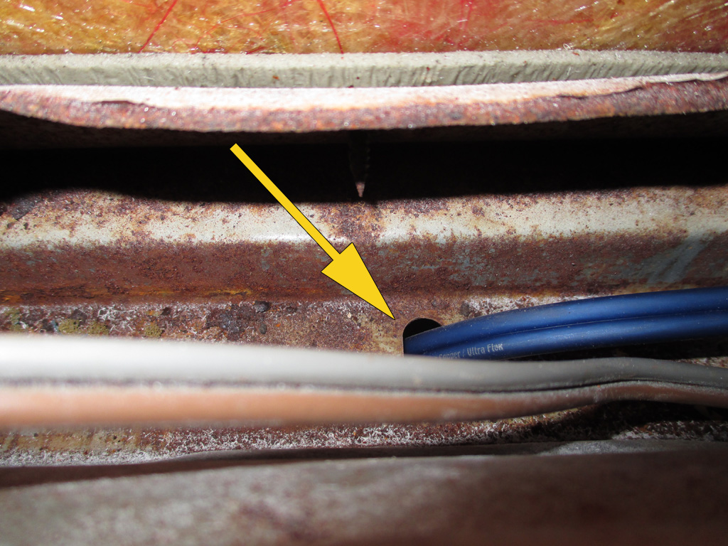
The passenger side was easy because the side panel edge was easy to unscrew from the side of the van and gently pry out for access. The driver's side where I needed access was smack in the middle of the wall. Not wanting to take the wall out to run my new wires, I removed the blinds and plastic trim from the window I wanted to drop the wires next to. I was then able to pry the interior wall out gently and peep inside the wall. The hardest part of this was going to be somehow getting my drill in the limited space to drill another hole as I did on the passenger side. Turns out I caught a break on the driver's side.
The roof side rail (where other wires had been run by the factory), where I'd run my new wires from the front of the van just happened to have a hole just the right size for my wires! Of course my round rubber grommets wouldn't fit the oblong hole (didn't even think I could get my fat fingers in there to manipulate one into place), so I decided to let the thick insulation of the wires do its job. When I pulled the inside wall back, presto... there were my wires ready and waiting for the next step. This went much more smoothly than I'd originally thought, making the job go that much more quickly.
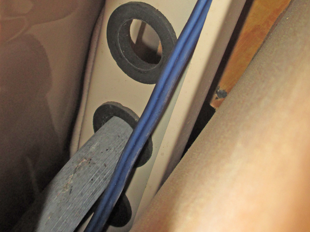
As with the other side, I ran a piece of stiff wire through a hole I drilled in the side wall adjacent to the new speaker location. I grabbed some Duct Tape, wrapped the speaker wires around the "feed wire" and pulled them throught the hole. Next, I crimped the necessary size spade connectors to the wires in preparation for the speakers getting installed. Oh, the big fat rubber hose running along the inside of the wall? My van has rear air conditioning, so my guess is the hose feeds freon to the rear evaporator coil, which means there's probably a return line hiding in there someplace too.
Flush with success, I rustled up some pan head phillips screws and physically installed the new speakers into their new locations. I was sweating quite a bit during this phase of the operation, working carefully so I didn't slip off the screw and damage the speaker. My luck held though and the install went much more smoothly than I initially expected it to go. What can I say... even I get to catch a lucky break once in a while.
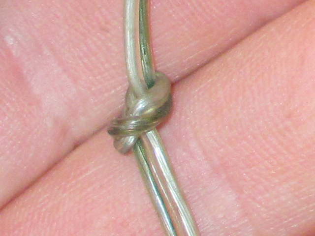
To gain access to the rear speakers, I removed the faux wood panel that held the ashtray, lighter and cup holder. So, let's say you're wiring your van and all you happen to have on hand are a few spools of speaker wire. Not wanting to take a chance on mixing them up, how do you go about marking which wires are power and which are speaker feeds? This guy's solution was to tie a knot in each power feed wire so he could differentiate between the two. I probably would've gone with my traditional duct tape and Sharpie method, but whatever floats your boat I guess. Me... I'm running dedicated speaker wire to my speakers and black/red wires for my power.
Not trying to be needlessly fancy, but I at least try to make an effort at a professional looking, quality install. My biggest fear at this point is that I'll forget to run the wires for a light or power port I've got planned and have to remove all the interior access panels again. I know for a fact that I've got some rear interior lights planned for the rear cargo area and some extra backup lights as well as my CB antenna cable to still be run. Of course the van doesn't need to be aesthetically pleasing during this construction phase, but I still want to do it once and do it right. Now, where the hell are my dikes?
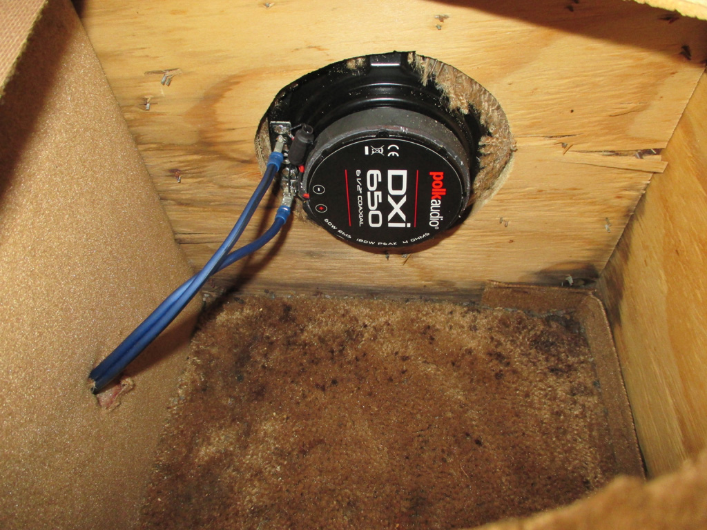
With the tricky stuff out of the way, I could get on with the job at hand. Utility knife to strip off 1/4 inch of insulation, twist wires, twist solderless connector on the same way and crimp 'er down good. Repeat. With that done, I mounted the new speaker in the old location with sheetrock screws. At first.
I failed to realise at the time that I needed to install the plastic ring along with the speaker, then the grille itself gets pressed into place. I removed the speaker, added the plastic ring and rotated the speaker 1/4 turn. Then I attached the grille and moved on to finish the other side.
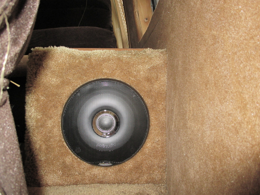
As seen here, the Polk Audio logo is embossed in the plastic which curves into the grille at the bottom. Oh well, a mistake caught early helped me avoid the same error on the opposite side of the van. Then I simply re-installed the faux wood panel with the ashtray and cup holder on each side and this part of the operation was a success.
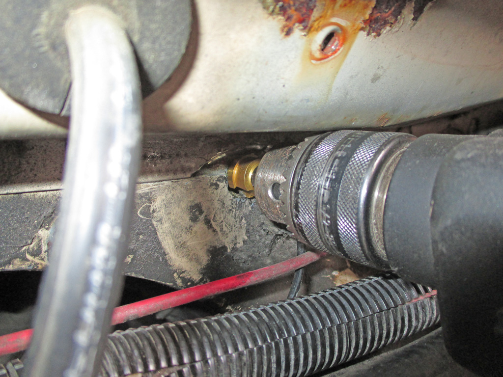
When I bought my van, all that remained of the original "windshield pillar" antenna were two plastic clips screwed into the pillar. The PO installed a new telescopic mast style antenna in the stock van location on the right front fender. Unfortunately, he obviously had no knowledge of how to do the job properly. The base of the mast section was screwed right to the sheet metal of the fender, effectively shorting it out. He also ran the antenna lead inside by slamming the engine cover shut on the wire! Well, I guess you can say he tried, but I just shook my head and pulled everything out to start over from scratch. Chevrolet placed the factory antenna too far forward for my taste in order to clear the under hood Air Conditioning equipment.
After much deliberation, I decided to mount the antenna on the driver's side where there was easy access. I've often wondered why the passenger side is chosen for the antenna when trees and overhanging bushes can easily whack them if you're on a street that isn't perfectly groomed. The big issue was... just where in the hell to bore a hole for the antenna lead and pass-through grommet? I finally found a spot where there was no interferance and drilled my hole. Since two pieces of metal overlapped there, I cut an arch out of the top layer with my Dremel so the grommet would fit properly.
There was a bit of rust here and I also knicked the inner layer of metal with my Dremel disk. So, I sanded the rust and wiped the area down with an alcohol pad before blasting it with some sandable primer. When the primer dried, I sanded it lightly with some 220 grit and shot some color on it with a rattle can.
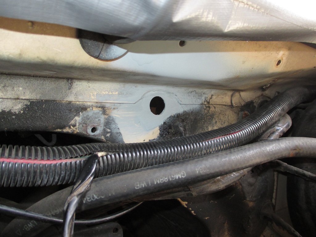
PRIMER
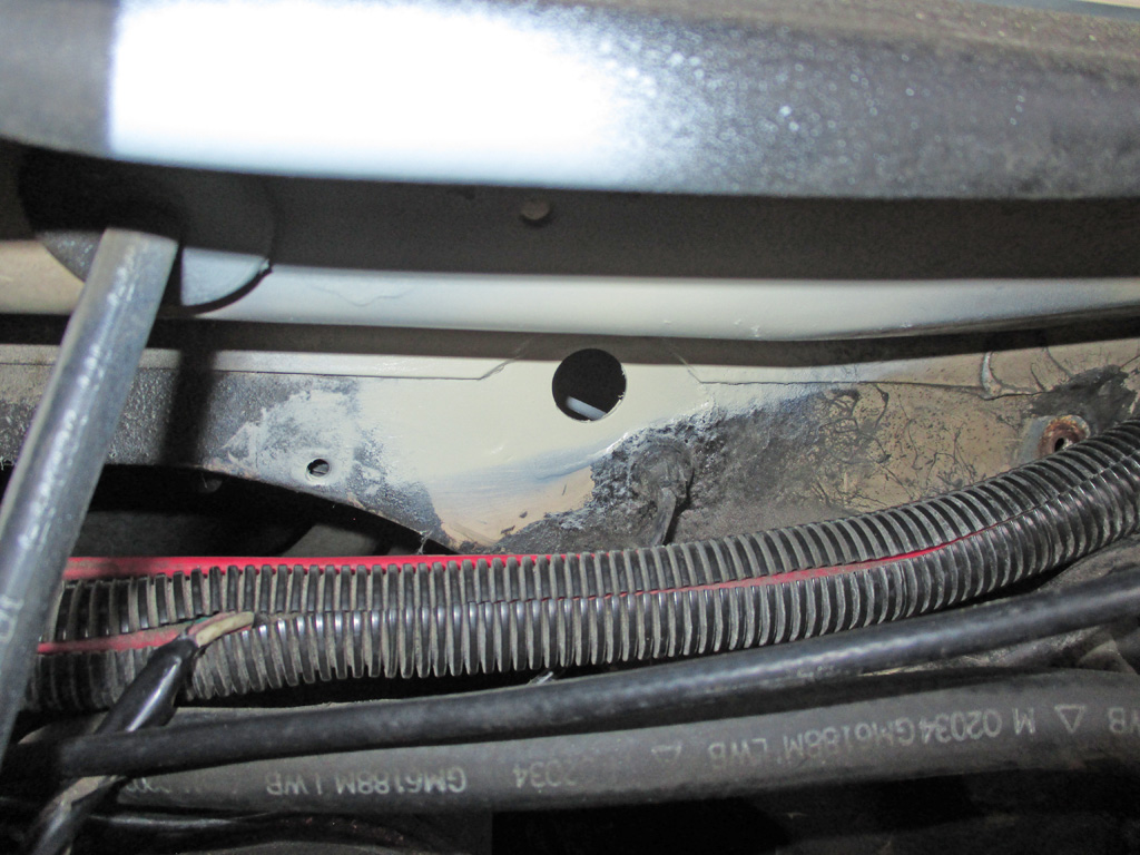
TOP COAT
It's not exactly perfect, but in this case you'll never see it when I'm finished. The factory sprayed a rubberized undercoating material everywhere a pass-through went through the firewall. I'll do the same thing when I'm finished and everything will look stock.
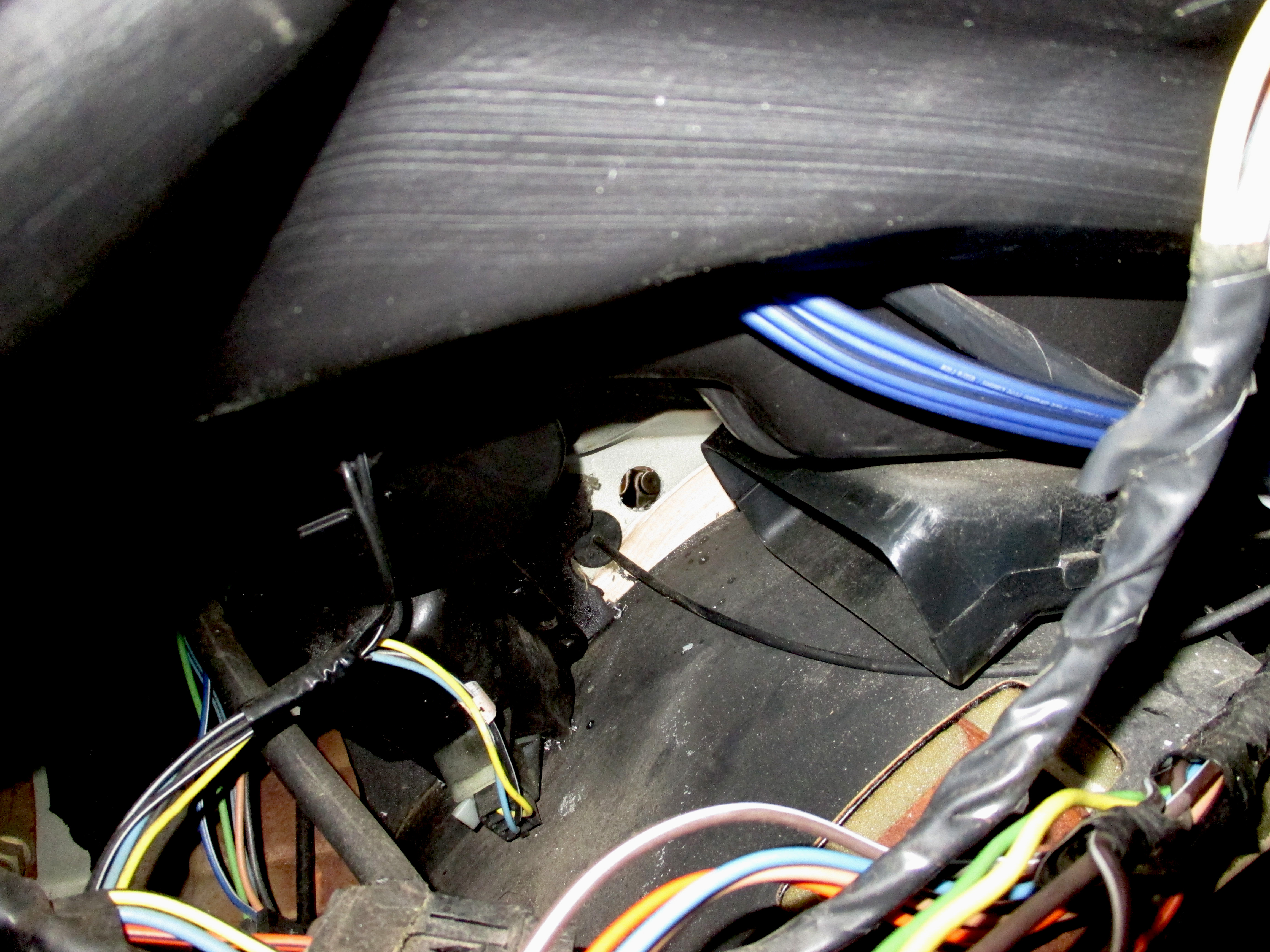
A big part of my problem was finding a place where there wasn't a defroster duct, wiring loom or some other object that would be in the way of me drilling a hole in the firewall. Above the main wiring loom would've left the cable too short to reach the radio. Then the power brake booster was in the way. The location adjacent to the vacuum line pass-through was perfect... if... I pulled a couple of panels off the dashboard and moved the HVAC controls to the side so I could see what was where. Amazingly this part of the firewall was blessedly free of interference, so I finally had my location.
The antenna I bought wasn't cheap, it was NOS I found on the bay of E and included a professional looking pass-through grommet. That would require a 3/4's inch hole in order to make a stock-looking install. If I ever have to, I can run another wire through it if I absolutely need to.
The PO also ran a hot lead for the radio in through the engine cover and jammed all the speaker wires behind the Heat/Cool lever making it impossible to move. Turns out that was the cause of my roasting feet on my drive home. Once I removed his radio (which may or may not have been functional, all I got was static) the Heat/Cool slider worked fine.
With the primer drying on the hole opening it was finally time to mount the antenna. I bought a model designed for a sloped fender which has a very sturdy mounting bracket and bezel compared to the "el-cheapo" versions I've seen. I measured carefully and centered it on the fender, coming as close to the windshield as I could while still having enough clearance beneath to rotate and adjust the mounting bracket. This took a while because I first drilled a hole the exact diameter of the threads on the antenna base not realizing I needed the hole big enough to accomodate the base mounting plate.
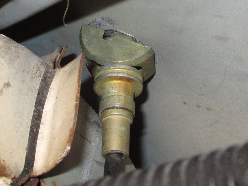
ENGINE BAY VIEW
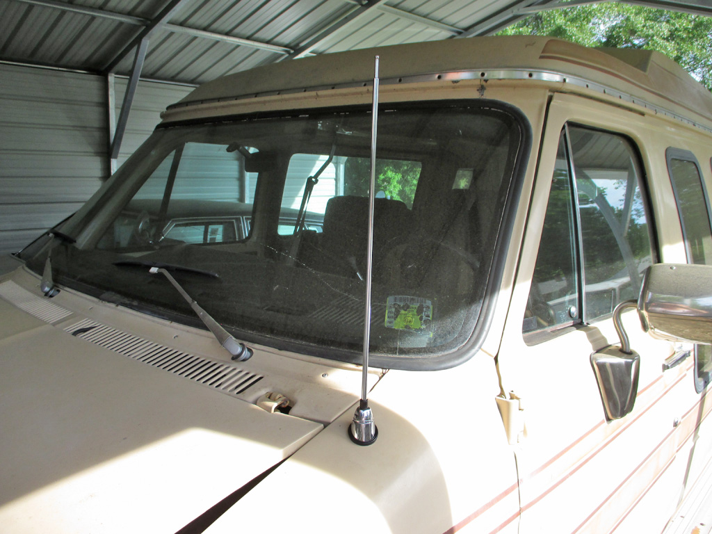
STREET VIEW
I took the battery out and set it to the side to give myself enough room to operate. Time slowed to a crawl. Grind the opening a bit with the Dremel (later changing over to a fine rat tail file), as I slowly snuck up on the proper diameter hole I needed. Then I would check the fit and see if the mast was perpendicular with a small level. Yes, I can be that much of a perfectionist. In the end though I finally said done. It's perfectly perpendicular from the front and raked back slightly to the rear when viewed from the side. No one but me will ever notice I'm sure.
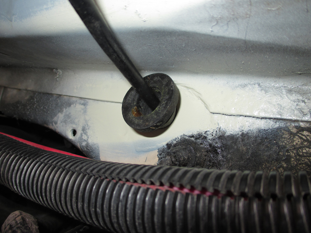
The final step was also the easiest. Shove the cable through the hole, push the grommet into the hole until it popped into place and then I can finish up the radio and equalizer installation. Both the cup holder project and the radio installation project kind of went hand-in-hand due to the location of both on or in the engine cover doghouse. I've got a vintage Pioneer Supertuner that I'd wanted to use, but the tuning shaft is broken. So instead I went with an old Cadillac radio that was in my "radio box" (clear plastic tote actually), of leftover stuff and installed it instead.
My theory is the van made the trip to the custom shop sans radio. Not sure what they installed (both it and the CB shared the same antenna), but it must've been aftermarket. I bought the van with a semi-functional Alpine unit that wasn't period correct. The Delco radio is actually from the same era. I deliberately purchased a vintage Radio Shack equalizer (still in its original packaging from back then), to keep things looking as they might've back when the van was built.
June 2014
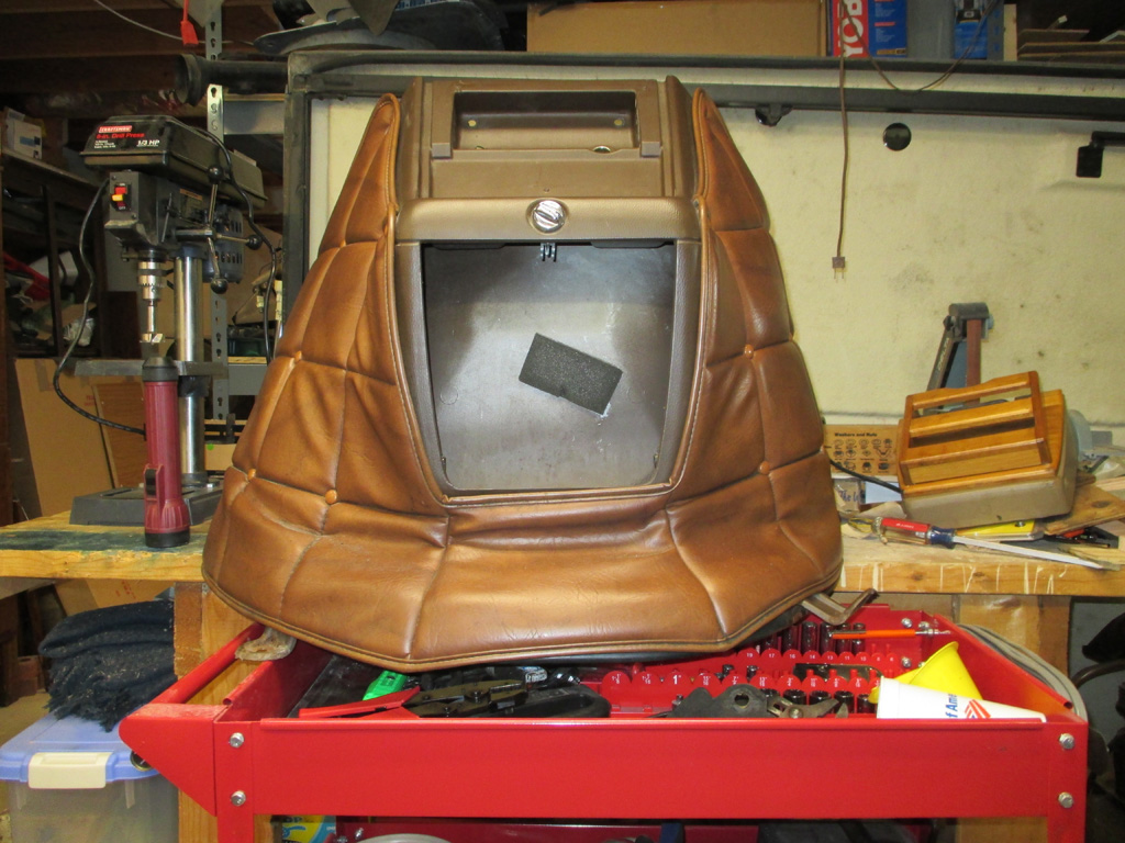
With the cupholder project completed, the next logical step was to finish the stereo install. This is a real milestone, completing two long-standing projects, finally catching up on all the things I started many months ago. Step one... cut an opening above the ashtray/lighter panel for my new graphic equalizer.
But wait... what the heck is going on with that engine cover pad? When I test mounted my cup holder, the right side of the quilted engine cover pad was being folded over by the bottom shelf. Now I can see why. The guys working on this were either hung-over from the weekend (Monday) or couldn't wait for quitting time (Friday) when they cobbled this thing together.
Obviously I am going to have to straighten this out, so the engine cover pad finally sits level, then the cup holder will look fully integrated. But before I can do that, I really should clean this cover up since its gotten rather filthy over the years. Clearly some Formula 409 and stiff scrub brush action is required. I'll also have to scrounge up some of the screw covers that have gone missing over the years. That ought to be a real treasure hunt for sure.
My primary objective for bringing the engine cover into my shop was to have unfettered access to the whole thing as I install the cup holder. The first step in this process is to mount the spacer board I fabricated so the bottom shelf will have proper support. The original was just screwed in place regardless of the dead space beneath the cup holder. I'm doing thing the right way... at least that's what I keep telling myself.
I created the spacer board using some plywood scraps of the proper thickness glued and clamped to a piece of 3/8's birch I had in my scraps box. The plywood will cover the factory cup recesses while the birch will mate up with the factory ridge (yellow arrows) as seen here. Is all of this really necessary? Well, I'm not really sure, but this is the way I've chosen to put my van back to rights.
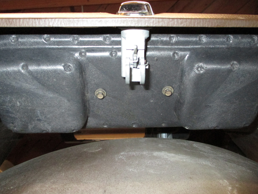
I rooted around in my automotive fasteners and came up with a couple of hex head panel fasteners and attached the spacer board from underneath. Using hex head screws enabled me to use a socket and my 1/4 ratchet to tighten them up. It would've been a real bear to try and get a screwdriver in the glove box opening. I would later discover how to take this assembly apart, making this an unnecessary diversion. Grrrrr.
Now I can attach my cup holder to the spacer board with a couple of drywall screws. I drilled two countersink holes in the recess of each thirsty stone coaster. When both coasters are installed, you'll never see the two screws holding things in place! I worked hard to design this so that all the fasteners would be hidden.

The quilted engine cover pad was both crooked and filthy, so needless to say, I removed it for cleaning and proper re-installation. This had the unintended effect of pointing out that the center stack of the engine cover was only mounted with two screws on the bottom edge. The two upper bolts (long since gone on my van) will be in the way of my planned Graphic Equalizer installation, so they'll be eliminated. To help hold the center stack in proper relationship to the engine cover, I needed to fabricate some spacer blocks.
I did this by mounting everything in position in the van and then used some Play Dough, squishing it into the gap to give me a model of what the spacer blocks I was creating would need to look like in terms of thickness and curvature. The Play Dough works great in situations like this. Once I have the spacer blocks in place, I'll be able to cut the opening for my EQ and know that it will be accurate.
With everything mounted in the van, this part would be extremely difficult. Since I have the whole thing sitting on my bench, I decided to kill two birds at the same time and install my EQ and the new cup holder.
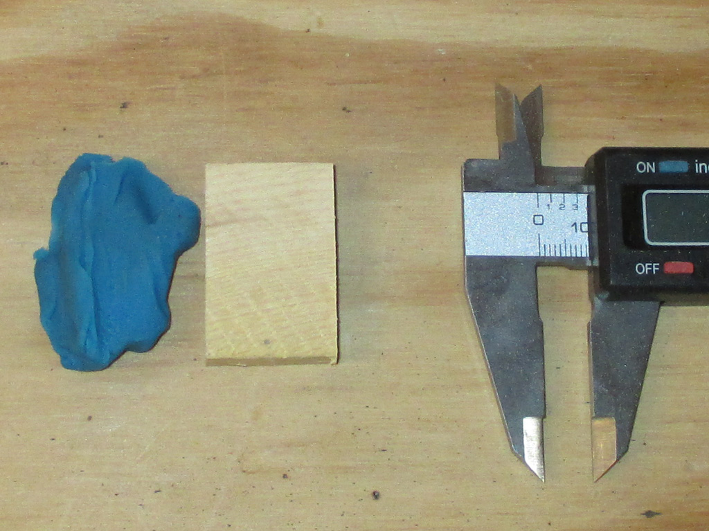
The second step is to use masking tape to mark where on the engine cover the Play Dough was, then carefully peel it off so I can measure the thickness I will need. Using a vernier caliper and a ruler I quickly dope out the thickness I'll need. Then it's a simple matter to find a wood scrap of the proper thickness and press it into service.
I had to repeat the process for both sides of the engine cover where the center stack mated up to it. This was necessary to hold both pieces in firm alignment so I could accurately measure mark and cut the new opening for the equalizer. I killed half a day just figuring this process out. Then it was on to the main event.

I used some contact cement for this part of the operation. Since you have to let this stuff cure for 1 hour, I puttered with other things while I waited. Then I used my drum sander to contour the block of wood, using the curvature of the center stack as a guide. Again, this process was time consuming, install center stack, check fitment, remove and sand more wood off the block. Repeat.

With the height and width of the faceplate marked out it was time to make my cut. I used a stone wheel in my Dremel for this part and had a fan blowing nearby. Even so the acrid smoke of melting ABS plastic filled the air as I carefully followed my scribe marks in the plastic.
The two factory bolt holes seen here will eventually be filled in with some plugs I plan on making out of the rectangular scrap of ABS that I cut out of this section. I may drill some smaller holes (wider apart too), should I deem it necessary to attach the upper section separately. It hasn't been since I've owned the van, so I'll have to wait and see.
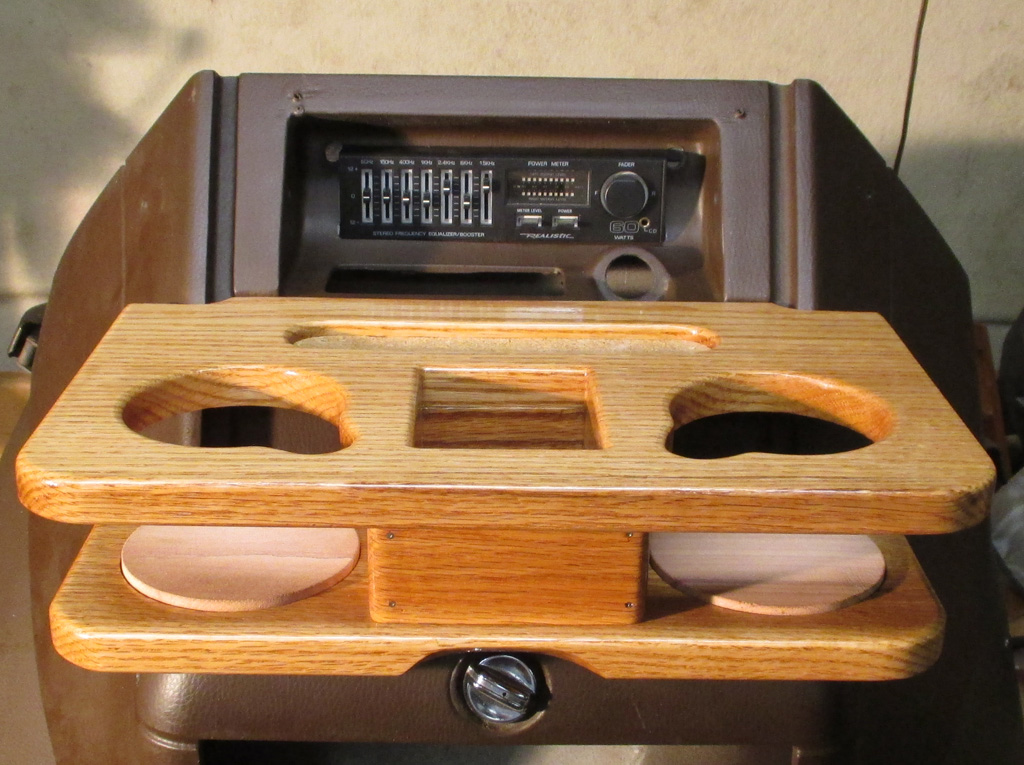
I managed to make it this far by the end of the day. The EQ opening has been cut and trimmed (although it will still need a final test mount in the van), and looks pretty good at this stage. Once I can confirm that the size and angle of the new opening is correct, I can make a small bracket to hold the EQ in place, rather than just letting sit there.
The cup holder is finished, glued together and permanently mounted to the center stack. All that remains at this point is to reinstall the quilted pad and do whatever modifications are necessary once I bolt everything back into the van. All tolled, it was an extremely productive weekend.
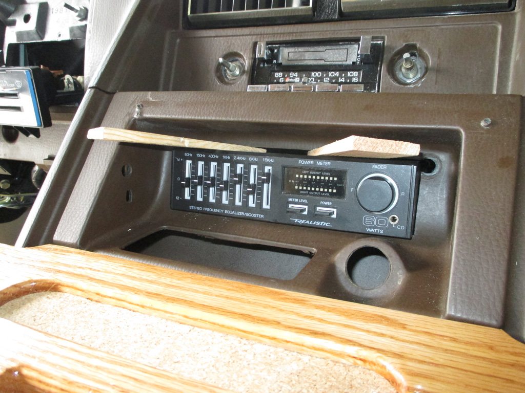
The best fit was obtained by wedging the face of the equalizer downwards to the bottom of the opening I'd cut. The angle of the equalizer was pretty much determined by the shape of the engine cover. My original plan was to have the faceplace extend just a bit from the opening for a clean look. Instead, the faceplate extends an inch or more from the opening I made. I also had to make the opening "taller" than the faceplate to allow me to tip the back of the EQ upwards and make sure the center stack would still sit flush with the dash.
My first try saw me wedging the unit up to the top of the opening, but it wouldn't fit flush, so I had to try another tactic. I wedged the EQ tightly into the opening, then carefully un-clipped the doghouse/engine cover and gently wiggled it out of position. Then I could mark exactly where the EQ needed to be.
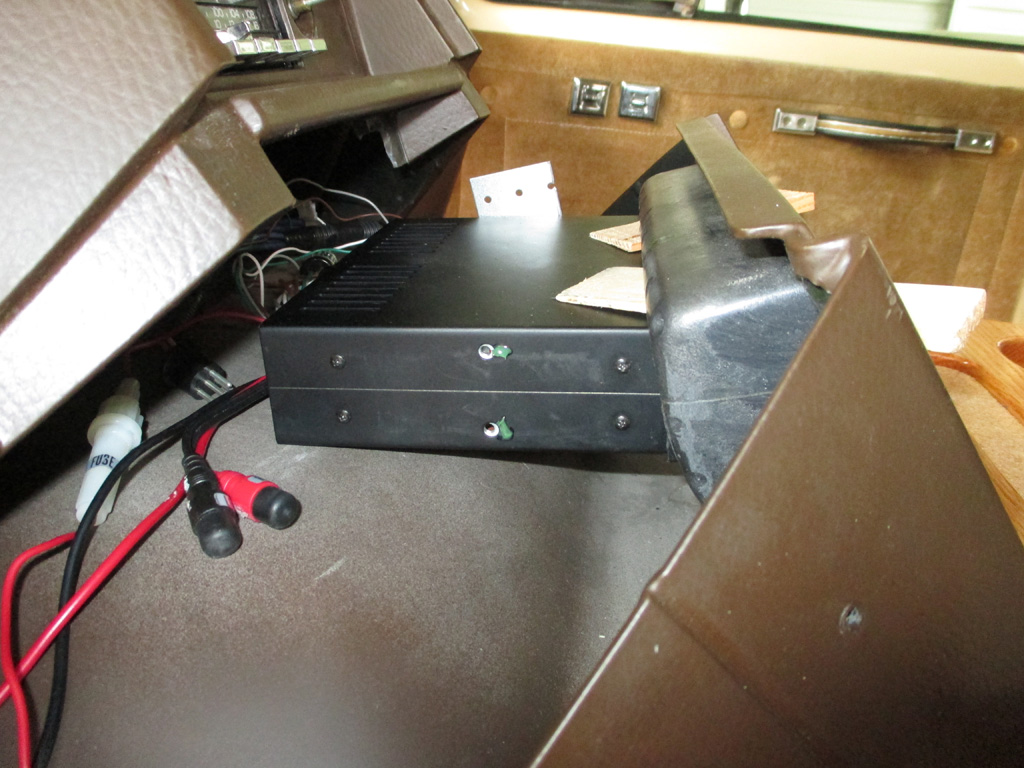
With the positioning of the EQ sorted, I had to fab up some brackets. I used some pre-drilled repair plates from the big box home center that I had laying around. None of the pre-drilled holes lined up (naturally), so I trimmed the plate, bent it at the proper angle (matching the engine cover curve), and proceeded to mark the holes. I put a dab of grease just in front of each hole, pressed the bracket into it and drilled each hole just rearward of each grease mark. This may not be the most accurate way to measure things, but it worked for me in this instance.
In the background one bracket has already been mounted to the EQ. Once I have both brackets mounted, I can mark where I will screw the bracket to the top of the engine cover. This turned out to be quite a long and detailed process. Cutting the plate in half giving me two brackets, marking where the holes needed to be drilled, multiple trips back and forth to measure, check, modify. Whew! I hadn't planned on this project eating up the whole day, but that's exactly what happened.
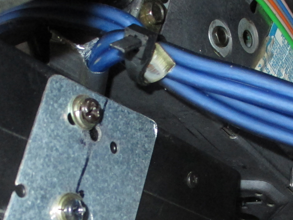
I'm not sure what gauge of steel these plates are, but they seem sturdy enough to do the job and they were easy to bend in my vice with my ball pein hammer. I used my angle gauge held up against the screw holes in the EQ and the other end on the curve of the engine cover where I wanted to mount them. Sounds pretty complicated when you type it up, but in actuality it was pretty straightforward. I was really surprised to discover that the engine cover itself was made out of fiberglass. This made it easy to drill the two mounting holes I needed.
Once I had them in position and everything lined up, I ran a Sharpie along the top of the EQ, marking each bracket. Once I had both of them out again (the engine cover getting heavier with each removal/installation), I cut them off with the Dremel so they'd look semi-professional. Of course if I wanted to be real anal, I could sand them, wipe them down with some alchohol and rattle-can them black. Who knows. I might still do that at some point if I get really ambitious. Then again, you'll never see them with all the trim installed.
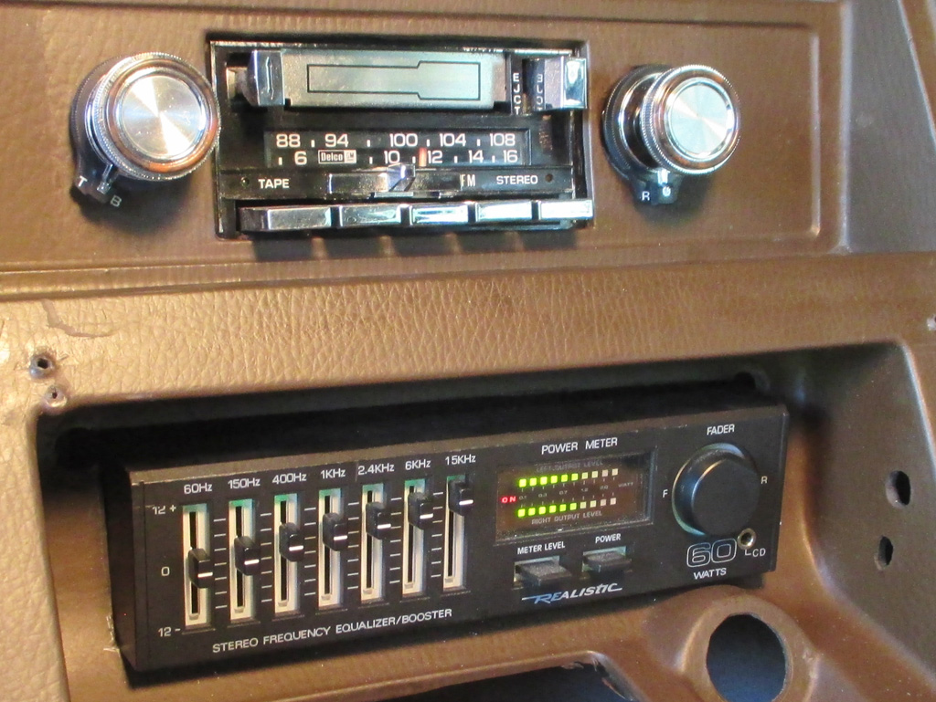
Finally, as the day wound down, I reached a milestone...the supreme test! I gotta say it looks really strange, seeing an operational radio (and EQ) where there's been nothing but empty holes in the dash for almost a year. I'm quite pleased with the results. The EQ's fader adjusts front to back, while the radio's original F/R fader control works sideways, adjusting right and left. Go figure. But in the end it doesn't really matter that much, besides... I've got a working radio again!
Now I have to take my temporary "alligator clip" power leads and wire them in permanently. For testing purposes I jury rigged the thing just to test how well it worked. The radio doesn't seem to pull in too many stations, so I may have to fiddle with the antenna trimmer screw. Overall though, a most productive day indeed!
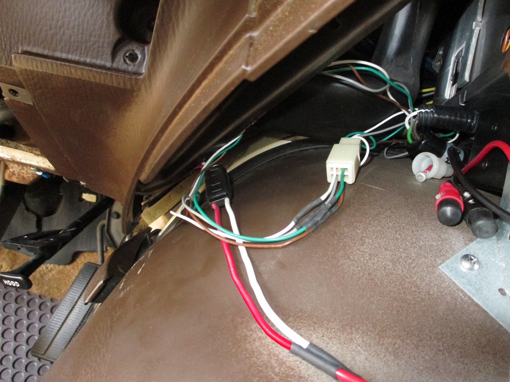
Since the engine cover is removable, I wired everything up with plugs/connectors so the engine cover and EQ can be removed when necessary. My big concern is what will happen when I need to take the van to some shop or another for a "professional" job. I'm thinking ahead here to having the A/C system purged and recharged with freon. That's something my humble little workshop is in no way set up to handle.
Who knows, perhaps the best solution is to simply undo all the connections myself so a ham fisted mechanic doesn't wreak havoc on my sound system. Of course I'd have to remove the EQ and cup holder, so neither of them get damaged during servicing. This is one reason why I made sure that the cup holder was attached with two screws, making removal an easy prospect. Gotta think ahead when designing a custom installation like I've done here. It isn't easy, but it is necessary.
August 2014
When I originally wired this baby up, I was actually pretty proud of the job I'd done. I thought I was leaving myself plenty of slack in the speaker wires to tuck up and out of the way. The problem I ran into, was that the connectors on the EQ were much shorter than I'd anticipated when I was running my speaker wires. I still had some slack, but it was minimal and required jockeying the wires out of the way while installing the engine cover. The fifth or sixth time I pulled the engine cover to do some work I was not nearly meticulous enough (or patient enough, let's be honest here), so I jammed it into positon and called it a day. It had been a long, hot, humid day and I just wanted the job done.
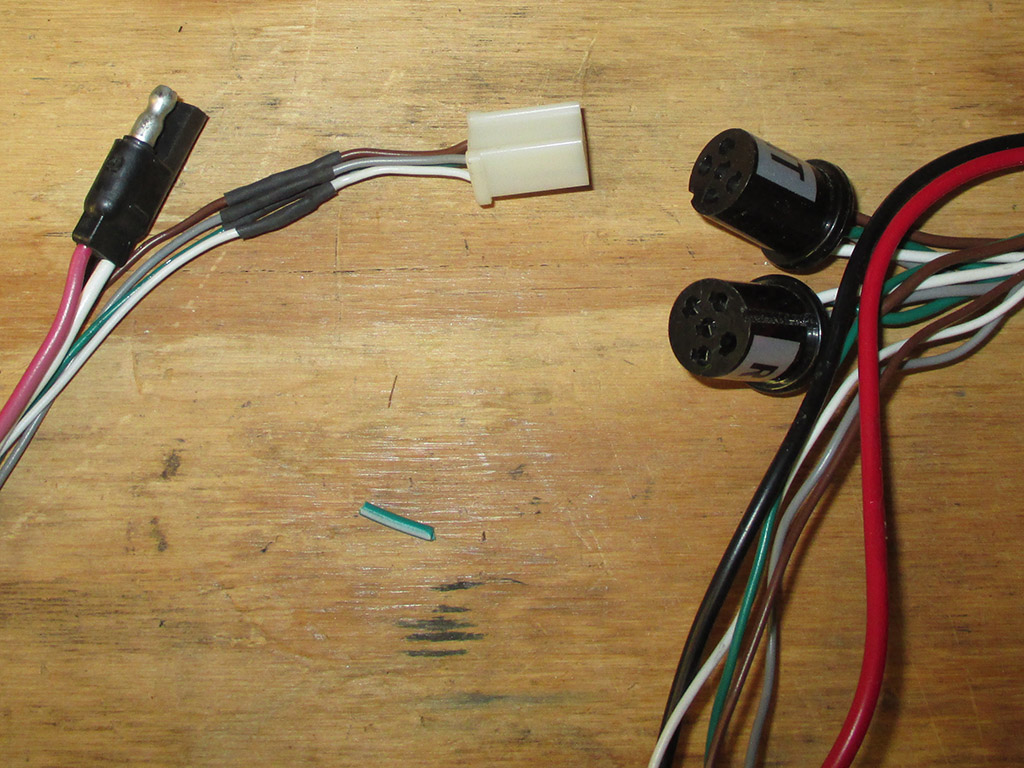
FOUR CONNECTORS
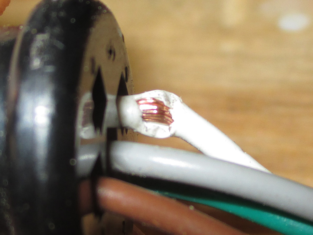
DAMAGE!
With a fresh perspective, I decided I needed a single connector for all the speaker wires. I would also lengthen the power leads, but wanted to keep them separate from the speaker connections to prevent any interference. Between the four input wires (from the radio to the EQ), and the eight speaker output wires from the EQ, I needed a 12 terminal connector that would lock together.
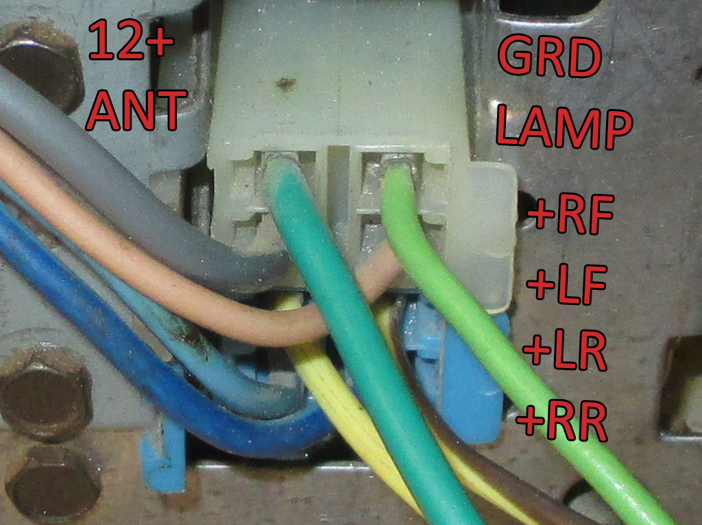
The first step in wiring up a radio is determining which wires are which. GM products of this vintage have the wire schematic stamped into the steel of the radio, but it's on the bottom and oriented backwards. Oh well, they made an effort at least. I transferred the schematic to a piece of paper, then doctored this picture in Photo Chop so I would have it to refer to. The radio has four speaker outputs. The EQ has two speaker inputs. In an attempt to balance things, I used the Right Front & Left Rear outputs of the radio to feed the inputs on the EQ.
The only EQ's I found with four speaker inputs were prohibitively wide for use in my van. I may change things in the future, but for now the radio plays fine the way I have it wired up. I just needed to tidy up the wiring I have, so it won't get damaged again in the future. The goal here is to have one speaker connector and one power connector to disconnect before removing the engine cover for service. Last time I was in a big hurry to have a radio in my van once more. This time I'm trying to engineer the installation to take service needs into account better than I did the first time.
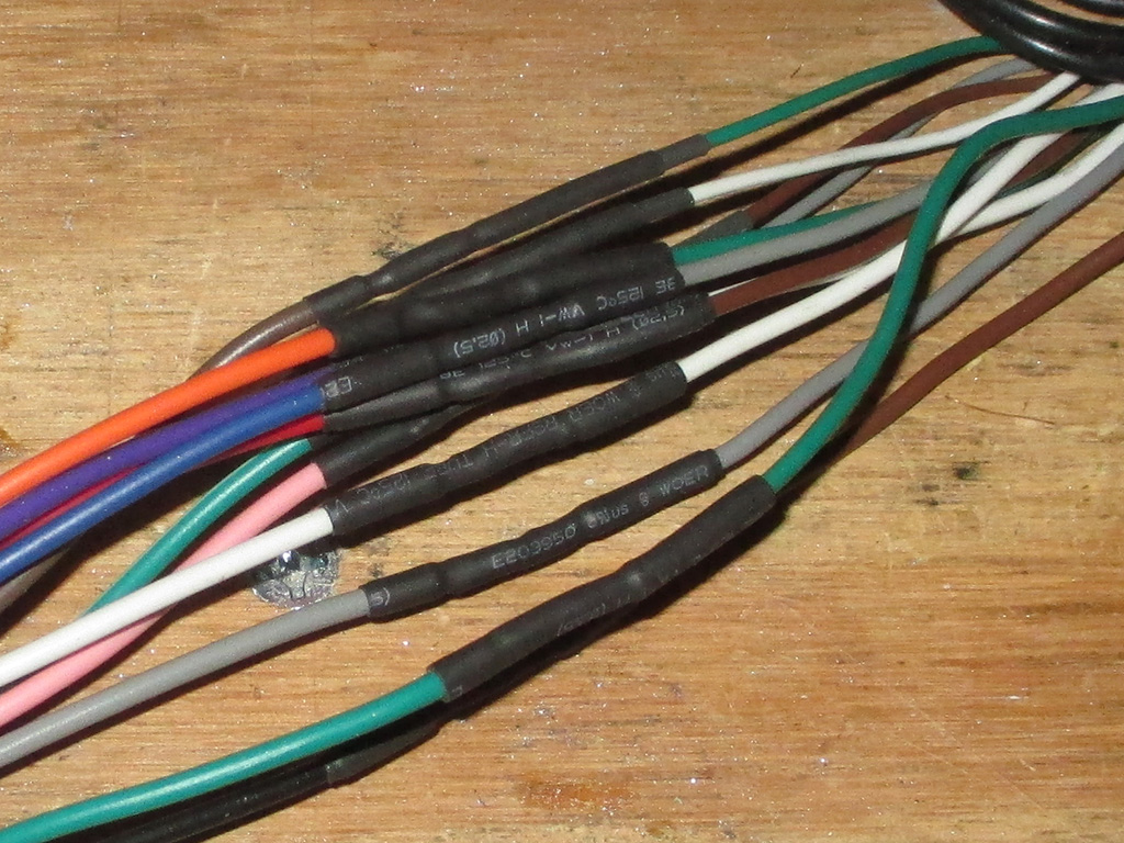
Some hunting on the Bay of e netted me a 12 terminal wire loom with a female connector on one end and male on the other... it will actually plug into itself! What you do is simply cut it in half, wire each half to the components you're trying to connect and presto, one connector for all those pesky leads. I painstakingly lengthened the four outputs from the radio by 6 inches (evening them up in the bargain), for some extra "wiggle" room. I ended up changing one radio lead from green to pink... I didn't have any green wire in my little stockpile... go figure.
Then it was simply a matter of stripping the insulation, soldering the wires together and using some heat shrink to protect my splices. I used a snug fitting piece on one half of the wire, then a looser section on the other half. Once in place, this will give me two layers of heat shrink on each connection I make. Slide the tight one over the splice, hit it with the heat gun, then repeat with the larger section of heat shrink. Super anal I'll admit, but I don't want to have to tear into this again after this repair session. I wasn't quite prepared for the way all this stuff fits into the dash on vans like this.
At this point, I have the EQ all wired up and ready to go back in. The radio outputs are all finished as well. All that remains to be done is to solder the speaker leads in the van to the remaining 8 leads on the radio/speaker harness I have created. The goal... disconnect two connectors to remove the engine cover/equalizer; unplug the three factory plugs (and antenna cable), on the back of the radio to remove the radio for service . It took quite a bit of planning and thinking to come up with this solution. There was no factory wiring harness for the radio when I got the van. With a little luck I will have nailed it this time.
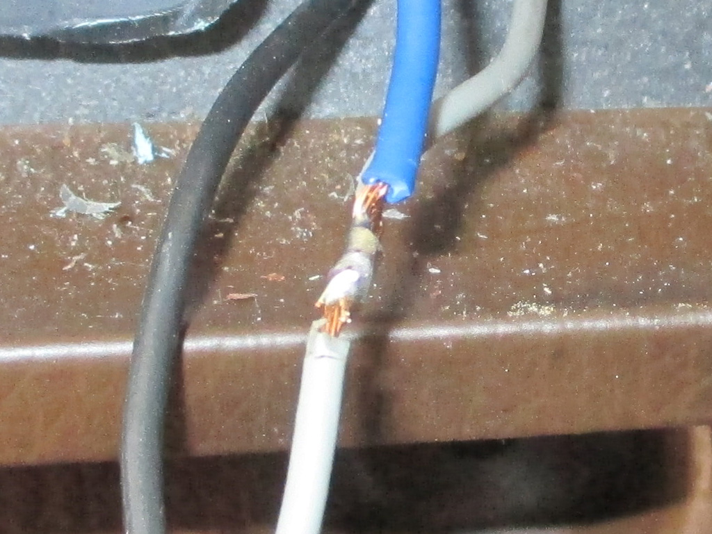
With the positive wire plugged into and empty "accesory" socket in the fuse panel (and the negative screwed firmly to a metal dashboard brace), all that was left was wiring up the dimmer lamp for the radio. I checked the terminals with my meter to determine which was the positive then stripped the factory wire, splicing in the feed to the radio.
I'm no fan of the 3M Scotchlok connectors (see explanation elsewhere in this log), so I do it old school. The positive lead for the radio and the EQ were spliced in a similar fashion. A piece of heat shrink, some black electrical tape just to be sure and we are there. In the end I have a safe secure upgrade that should provide years of entertainment.
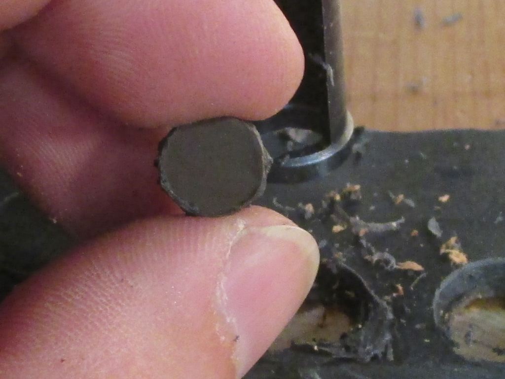
I am planning a new "door" to cover the EQ (so I can run my iPod in stealth mode), which will also require new hinges. To that end I decided to fill in the holes left by the old (and rather stupidly designed) middle pivot door the factory installed. It was a flip-up affair which (when open), covered up the area I have put to use as a home for my EQ. It was a truely mind boggling waste of space, so I decided to change it. Of course the conversion company had screwed its cup holder over top of it rendering the factory ashtray and lighter useless, which was doubly stupid.
Anyway I decided I would fill in those holes with some of the scrap I cut out for the EQ. Then I got the bright idea to use some of my woodworking plug-cutter bits on the plastic. Hey, if it works on wood it should also work on plastic too, right? Turned out I hit the nail on the head with this idea. A perfectly round plug of the right diameter to fill in the old pivot holes.
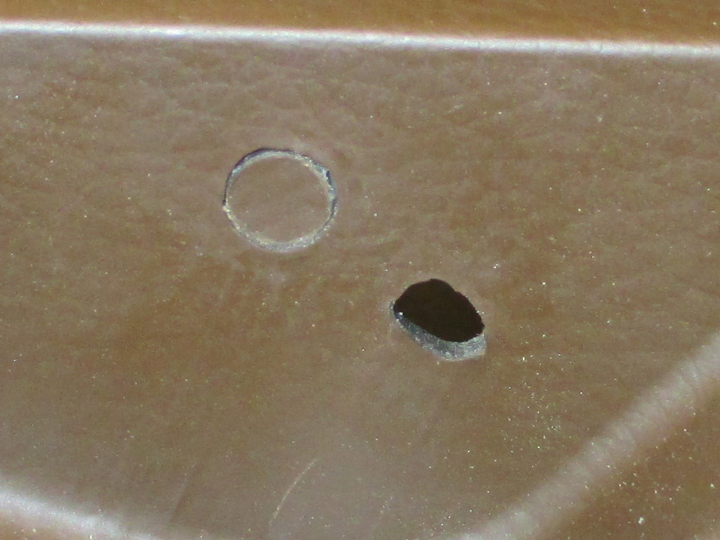
From a distance, I think my little solution to filling the unnecessary holes is just fine. The plugs actually turned out to be thicker than the panel I was inserting them into, leaving just enough plastic to melt the plug into place with my soldering gun equipped with a smoothing blade. Nothing quite like the acrid smoke of melting ABS plastic to let you know you're in the midst of a serious modification.
The remaining small oblong hole was used to hold the door in the open position via a small plastic nub on the door. I'll probably fill those too, hand cutting the plastic with Mr. Dremel. Really anal I know (and far from perfect) but my hope is the new hinges will cover this area anyway, so it won't really matter. I won't know that for certain until my hinges arrive, so we'll see how things turn out.
Interior
Wood 'N Wires
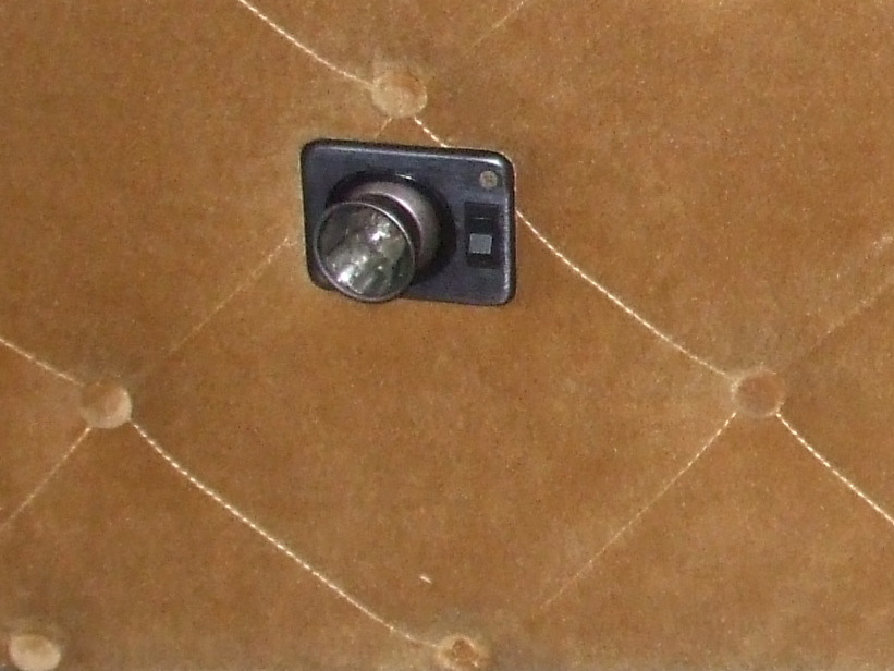
Since it was a nice day, I plugged in my work lights and began to carefully remove some of the damaged panels. This is where I started, the front headliner that is attached to the roof of the van over where the driver and front passenger sit. It was hanging low and actually dropping rather large splintered sections of dry-rotted wood whenever we hit a bump in the road.
The screws the conversion company used seem to be fine thread sheetrock screws, which got wet, rusted and are now a bear and a half to remove like normal screws. Some came out like screws are supposed to, while others had to be ripped out of the rotted wood with a crow bar.
As I grappled with this panel it began disintegrating in my hands snapping, crackling and popping like an out of control bowl of Rice Crispies. I attempted to cover the front seats, but didn't do a very effective job. That meant I had to go down to the basement and drag up my mini shop vac. I really love this thing. It has all kinds of suction, but is smaller and easier to maneuver in the confined space inside the van.
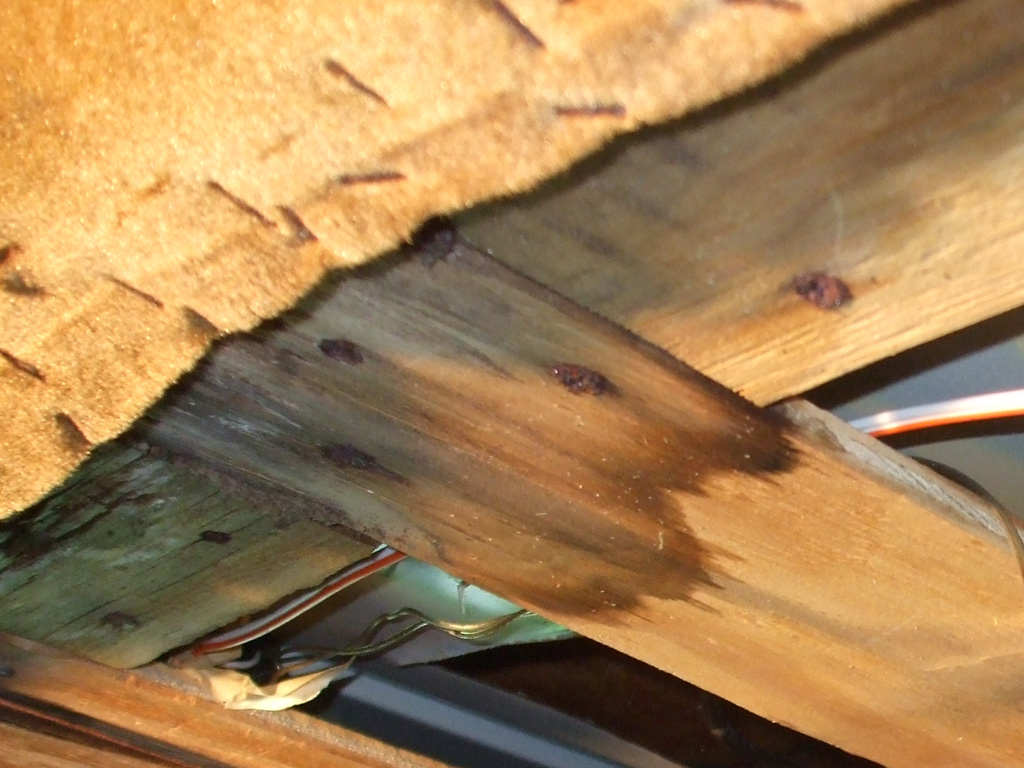
Once I saw the condition of the wood, I immediately decided to remove all the mold/water stained wood and rusty fasteners. The difficult part was doping out which panel needed to be removed first (the headliner over the driver and passenger front seats), since I had no idea how the thing was built back in the day. Judging from the stained wood and the rusted screws, this leak problem had been going on for quite some time. Since my plan is to eliminate the problem once and for all, I plan on replacing the damaged wood and fabric, making some modifications as I go.
It appears as though a thin layer of luan plywood was stapled (with roughly 50,000 staples), to the top edge of the fascia, then the consle was screwed to the roof panel. One at a time, I removed each screw and observed if the console got any looser, or if it stayed put. The process of elimination personified.
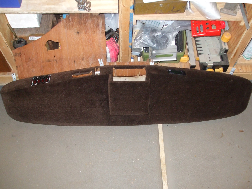
The headliner had to be removed before I could accesss the screws that held the console to the roof of the van. I need to reconfigure this to hold my own equipment, since I'm eliminating the TV from the center positon (ridiculous location for it), as well as moving the clock to the driver's side and replacing the fused switch panel with a newer unit. The brown velour that covers this is in fine shape, but I'll have to find some newer matching material after I reconfigure the plywood the material covers.
Another plus (for me and wifey that is), is that whoever owned this van didn't smoke. They couldn't have because you'd smell the smoke in all the fabric as that penetrates every kine of material there is. I have all the materials I need to effect the repairs (have in fact had them for over a week now), all I need is time and of course, access to the area that needs to be repaired. Thankfully, this panel (which runs along the upper side of the high top over the sliding side door), had minimal water damage, so I may be able to reinstall it as is.

Now keep in mind that I'm only doing this because the sky lights leak like a sieve, but in order to get to the screws that attach the trim panels, I have to take out about six other overlapping panels first! I did kind of view this purchase as another hobby at the onset, but I never envisioned taking apart the whole interior to effect repairs. Although I must admit that after finding a defunct mouse nest (complete with mouse "pellets" and the distinct odor of piss), I didn't regret the tear out quite so much. I plan on replacing the backing wood and washing the fabric to hopefully solve this issue.
The only downside to all this removal of upholstered panels is I now have to find someplace safe to store them until I can get to the skylight windows, which is after all, my ultimate goal. You don't really appreciate just how big a van like this is until you begin to dismantle it. I have all the materials I need to effect the repairs (have in fact had them for over a week now), all I need is time and of course, access to the area that needs to be repaired. Thankfully, this panel (which runs along the upper side of the high top over the sliding side door), had minimal water damage, so I may be able to reinstall it as is.
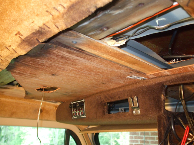
I originally thought this hole was to disipate heat, but further investigation proved it to simply be clearance for the swiveling lights above each front seat. Since I am eliminating the two mini spot lights (opting instead for an integrated dome light with two swiveling spotlights), the replacement luan wood will not need clearance holes.
I find it rather amusing that the guy I bought the van from so was proud of having "straightened out" the wiring. Telling me that the previous owner (his ex-girlfriend's grandfather according to the legend), had screwed everything up. It's always interesting to listen to story tellers conflict their own plotline... unless of course, grandfather was an electrician or something. Who knows, anything is possible I guess. At any rate using 22 AWG speaker wire to feed the 16 AWG wire the light fixture was originally wired with isn't what I would call an expert repair. Nothing I'd tout as being proud of that's for sure.
I plan on ripping all this junk out post-haste and I will start over fresh, using the proper gauge wire to handle the current load I'm running. Using what you've got on hand is one thing, but bodging the wiring like this is unacceptable.
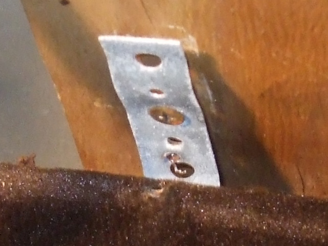
Here's one of the straps that secures each rear corner of the overhead console to the roof panel, in some cases going all the way through the wood and into the sheet metal of the original van's roof material. More of a reference shot than anything else, this will be a reminder of how the console mounts to the van. That way when I go to reinstall the console I'll have a pretty good idea of how it was mounted.
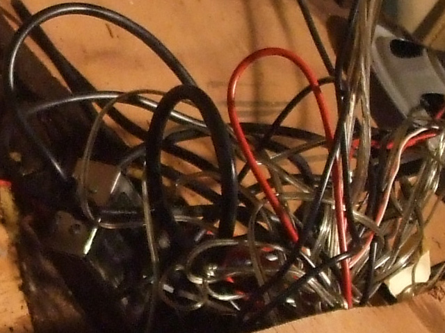
Having previously noticed that there were no speakers in the front dashboard area, I naturally set about ordering a pair so I can have some tunes in my van. One thing I hadn't anticipated was that the company that did the conversion might have relocated them. You know someplace subtle and not readily visible.... like over my freaking head! Having tried the aftermarket radio the PO had installed once or twice (receiving a blast of static for my trouble each time), at no point did any sound come from the console over my head.
So now I have a pair of 4x6 Polk Audio speakers (high performance units with polypropylene cones and rubber surrounds), which I can either mount overhead (I plan on using a new piece of 3/8" plywood to replicate the original) in a reconfigured console, or in the dash. I could always order another pair of Polk Audio 6.5" speakers (the ones I already bought are destined to replace the shredded OEM speakers in the rear of the van), which feature the same high performance construction. Not sure which way I'll go yet.
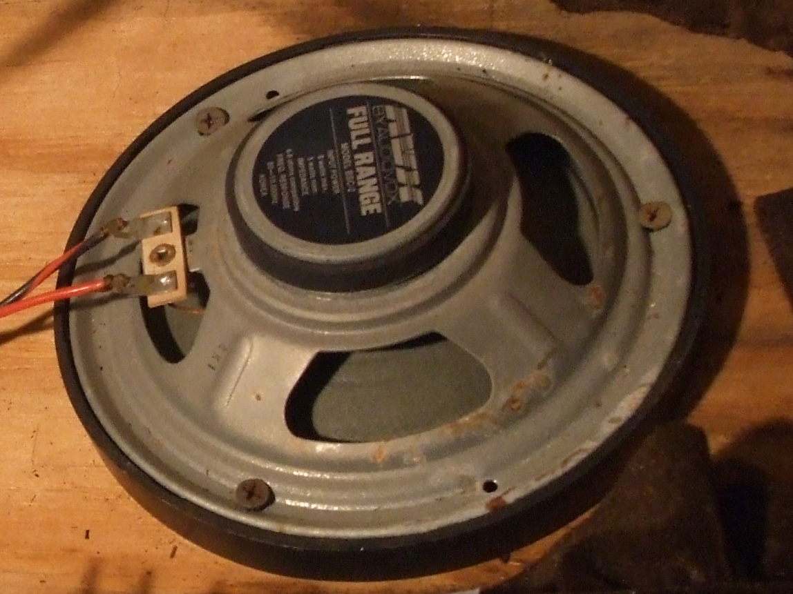
Here's a shot taken from the opposite angle. Gen-u-ine made in the 1980's Audiovox 6" speakers. I remember Audiovox from back then. Nobody wanted one of their units in their dash unless they were broke. The tuner lacked sensitivity and the cassette deck would start eating tapes soon after you put the unit in. I don't miss 'em at all.
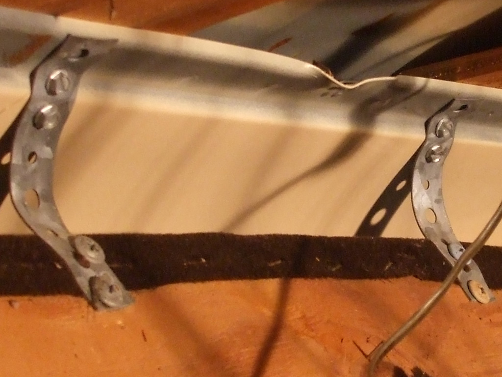
This shot is to illustrate just how the overhead console was mounted to the roof of the van back in the day. They screwed two straps to the console, screwed them to the roof of the van and when they pushed the console up, there was enough strength in the straps not to sag down over the years.
One idea is to use a couple of interlocking plates, one pair mounted to the van the other mounted to the console. Then I'll place one plate on top of the other, shove them forward, then mount the two back corners with sturdier brackets. Or, I can screw two plates to the console, cut two matching slots in the steel that runs across the top of the windshield and slide the plates into the slots. Either way should be much sturdier that what I removed.
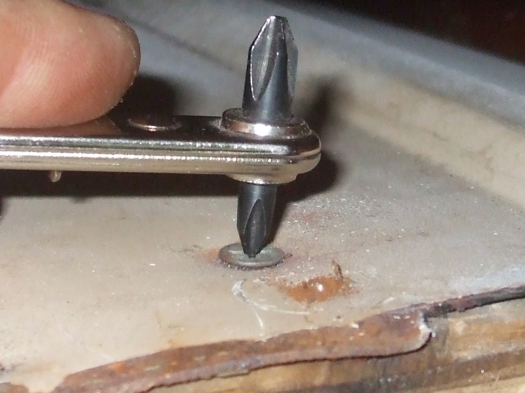
Things got tricky during the deconstruction phase, as the original builders obviously ran some screws in from above, before installing the raised roof section. This meant I had to get creative, since even my "Stubby" Phillips screwdriver was too tall to use in here. Some screws I had to tag-team with the Dremel, my small Vise-Grip pliers and of course my offset screwdriver. Some of the screws were so badly rusted they broke right off. Those I couldn't get a grip on, meant it was time for the pry bar to forcibly separate the wood from the steel.
It was some crunchy good fun as all the snap, crackle and popping of the wood was almost comical as it resisted my best efforts valiantly. In the end though, I was too much for it and I was able to get everything out in one piece so I had a template with which to mark my wood for cutting.
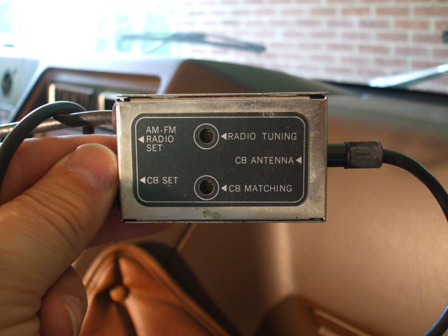
Here's another original piece that dates the van to the early 80's. A genuine AM/FM/CB radio antenna splitter enabling both units to use the same antenna. As with most compromises, the CB performance leaves a lot to be desired compared to a dedicated CB antenna. Guess I'll have to come up with another solution to mount a CB antenna to the side of the van.
After a thorough amount of cogitation on the subject, I have decided to not use the signal splitter as originally installed in the van. A compromise at best, I want to be able to reach other units further away than a couple hundred yards, I better pony up for a dedicated separate CB antenna. That being said, I removed the K-Mart antenna the van converters originally used, drilled a hole in the fender and installed a vintage NOS antenna in place of it. Found on eBay... naturally.
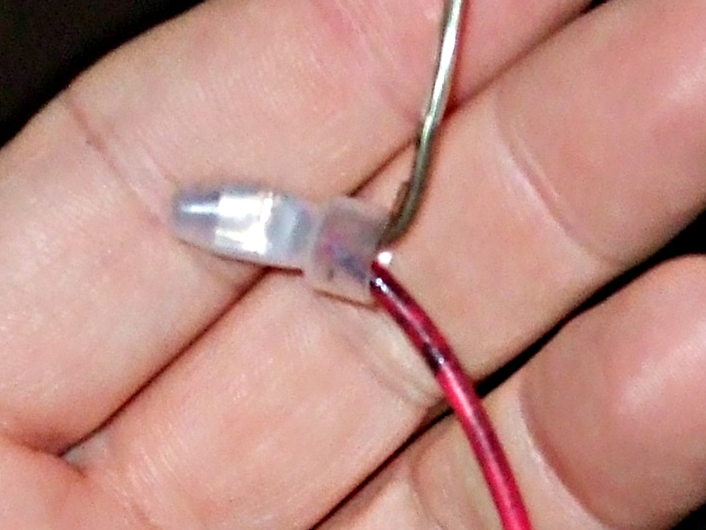
Spaghetti Explosion!
At the end of the day, I'm not really worried though. Once I get all the overhead upholstery removed, I can rewire everything the right way. I've even got a vintage overhead console (with a period correct switch/fuse panel) to replace the one that came with the van.
Below, the remains... plank 1 (click to zoom), mounts to the underside of the original steel roof, plank 2 screws beneath that and plank 3 (closest to your noggin when installed), is a set of spacers between the planks running forward to the windshield. All of these "planks" provide mounting points for the overhead console and cockpit headliner.
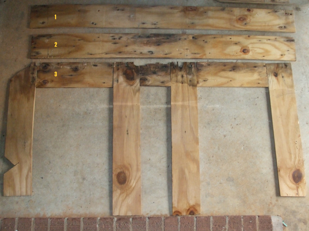
LAID OUT FLAT
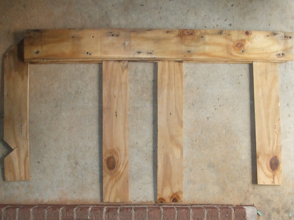
AS INSTALLED
I purchased a new 4x8 sheet of 3/8 plywood at the local home center which I'll cut up using the old wood as a pattern. Of course this will only be a jumping off point as my plans include installation of a newer television for the rear seat passengers, necessitating reconfiguring the existing setup.
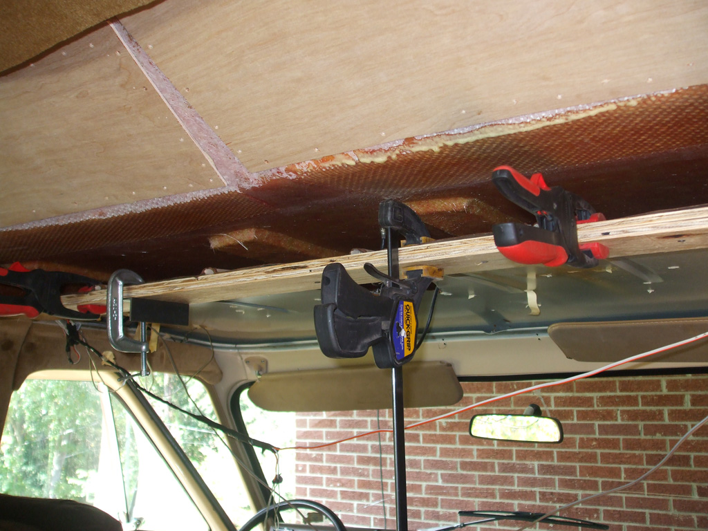
In this shot, I've installed the new piece of 3/8 against the roof and built down a second layer (prematurely in hindsight), beneath that. In a nod to tradition, I'm using fine-thread drywall screws just like the original builders did. Not that I'm trying for a numbers-matching resto here, simply using what I had on hand to save a trip to the home center.
I even got super anal and measured the screws out, 10 inches apart so I don't burn through 50 of them like the van conversion company did. The ADD vanner looked at the jagged roof opening edges and thought "I can neaten those up considerably with my Dremel tool," for a moment or two, but a reality check made me realize that was way too much dicking around for something you'll never see.
With the pleasant aroma of freshly cut plywood in the air, I began to feel a real sense of accomplishment... but the moment was fleeting. Unfortunately (in my zeal to install my new wood), I failed to realize that I can't finish the install without running new wiring for the overhead lights and cigarette lighters first, since the wiring runs both above the wood and behind the upholstered panels the wood butts up against. Wonderful.
Seat Upgrade
June 2014
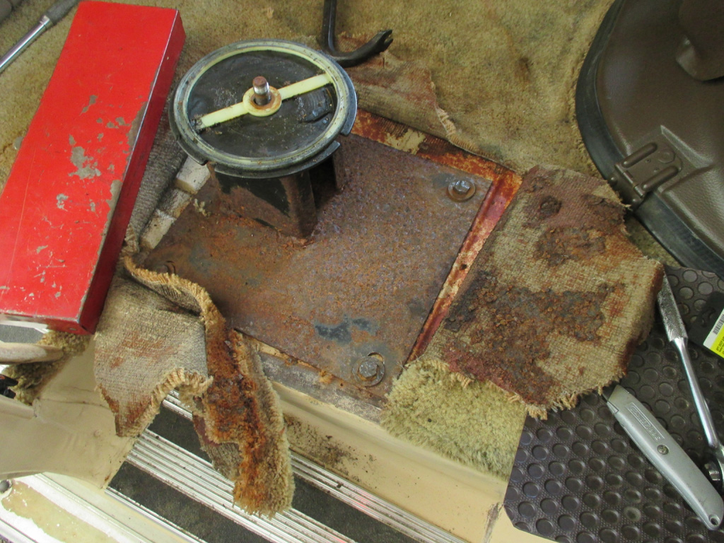
Sunday dawned wet and gloomy (despite no warning whatsoever from the so-called meterologists on tv), so I held off on the planned fiberglass work. South Carolina (knuckling under to federal funding pressure) now requires you to buckle up every time you drive -- even developing a catchy Click-it or Ticket add campaign. On my van, the passenger side seat belt does not work. Every time I take my van out for a spin, everyone tries to buckle up do it or be sent to Gulag for 30 years but even with the replacement unit salvaged from another van, it refuses to function.
Another salvage operation from a '95 Chevy van yielded two front captain's chairs, complete with bases, seat belts, the whole shebang for $40 apiece. For that price (not to mention the upgrade to 8-way power driver's seat), I tossed them into the back of my pickup for the day when I would replace them. That day is today.
Without further ado, I dove in headfirst and unbolted the seat from the original swivel pedestal seat mount my van came to me with. Then I removed seat mounting plate from top of pedestal. Sounds simple doesn't it?
I can recall a great deal of strutting and posturing by local politicians when the proposed seat belt law first came out. No federal "revenuers" were going to dictate to South Carolina what laws to pass and when, was the gist of it. Then the issue of federal funding for roads reared its ugly head. Amazingly enough, all the strutting and posturing came to a rather abrupt end. Along about then, the click-it or ticket campaign began.
I guess it really does make sense, but when good ole boys are used to hopping in their pickup to go to the Little Cricket for some smokes, buckling up first? Uh... no. I'm old enough to remember the federal "safety interlock" seatbelts that came out in 1974. The car would not start unless the belts were buckled! Folks quickly adapted and started fastening their seatbelts... BEFORE getting into the car. Then they got in, sat on the buckled seatbelts and started their car. This quickly changed to the reminder buzzer/light we have today.
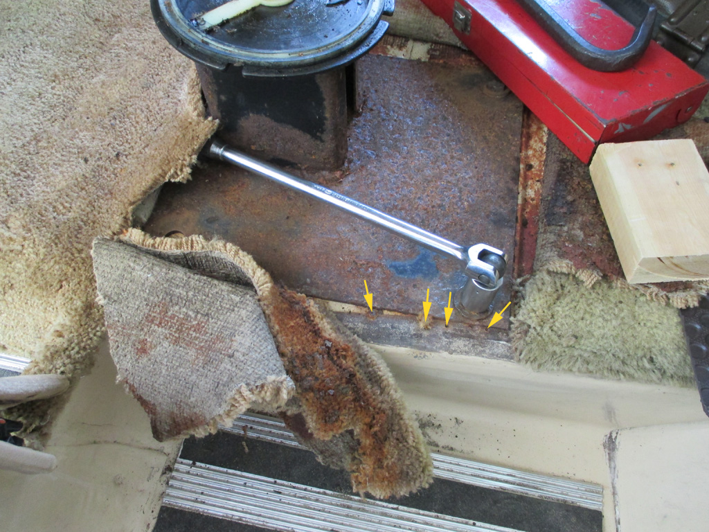
Now, where was I? Oh yeah. When I cut the carpeting back enough to expose the pedestal base, I found tons of rust. I broke out the putty knives and wire wheel equipped drill and went to town. Since I work alone for the most part, the next step was to mount the appropriate socket into my breaker bar, set it so it wouldn't turn and then slide under the van. I needed a 16 inch length of pipe (not to mention copious amounts of PB Blaster), added to the ratchet handle to break the first bolt loose.
That was the only nut and bolt assembly that worked as designed. When the second bolt head slipped in the socket due to all the rust, I came up with another plan of attack. The yellow arrows are the sheetrock screws the conversion company ran through the folded over edge of the carpet and into the floor of the van.
I think someone broke the passenger side window to gain access to the van at some point. Before the window got replaced it must've rained and the carpet got soaked rusting the metal. It's only a theory of course, but when I replaced the power window motor in the passenger door, evidence of window replacement (in the form of RTV silicone instead of actual window adhesive), was obvious. But I digress.
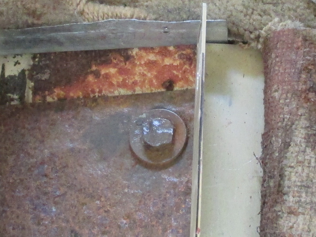
Once I saw that the nuts and bolts were going to give me a hard time, I broke out the heavy artillary. I used the cut off disk to cut the heads off the two front bolts. I think these must've been Grade 8 or something because these babies were tough. I placed some plywood against the Caddy for protection from sparks, but then the carpet caught fire... slightly. I dumped some water on it, mopped up the excess with a paper towel and fabricated some thin metal "shields" to keep the problem from happening again.
In fact, I ran the angle grinder so much that my compressor overloaded my workshop and popped the circuit breaker. The grinder kept slowing down until I looked up from the task at hand and saw the darkened workshop. I have a dedicated line for an old window air conditioner that is no longer used so I need to rerout the wire so only the compressor is on that circuit. Just what I need. Another home improvement project.
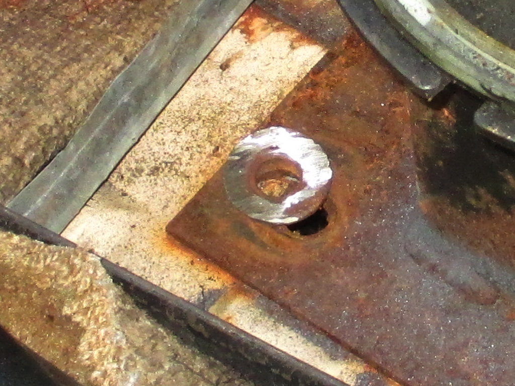
The outside rear bolt was the one that behaved like a nut and bolt. The two fronts were cut off with a cutting disk, then I used the flapper disk to grind off all the hex head metal so I could use a punch to remove what was left. The inside rear bolt was a B I T C H. I couldn't get the angle I needed with the cut off wheel and had to use the flapper wheet to grind down the whole entire head of the bolt. Took forever.
In the end though I was successful and removal of the old pedestal was finally within my grasp. The next time I move the van I'll pick up the bolt remnants from underneath. Now at least I can move forward with the upgrade of the passenger seat.
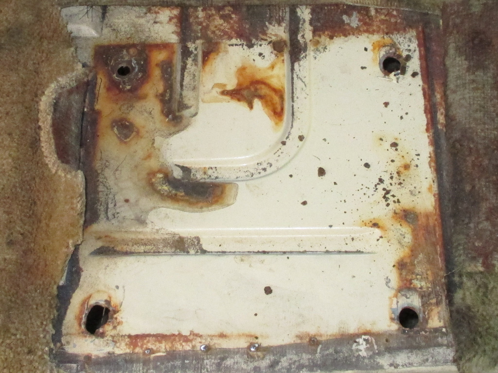
Thankfully it looks as though all I have to deal with is rust stains on the floor where the new base will be installed. The outside rear hole looked like it was cut with a torch at first. As I studied it, I think they enlarged the hole too much and added some weld to close it back up again. Even so, I should really give this area a little hammer and dolly work to level everything out. Not quite sure how to go about this, but something will occur to me eventually.
I took this shot before I vacuumed up all the black grinding dust and additional rust flakes. Temporarily the plan is to re-trim the carpeting to match up with the new seat base. The brown stuff outside the base of the pedestal appears to be some kind of adhesive use to keep the carpeting in place. I discovered this same stuff on the wheel well and it was pretty easy to remove the carpet from this stuff.
As I embarked upon this journey, I thought the studs (not bolts this time but studs welded to the base), looked like they had the same spacing as the pedestal I'd just removed. I was hot, sweaty and beat from all the work that this "simple" little modification turned out to be, but I just couldn't resist setting the new base in position for a look see.
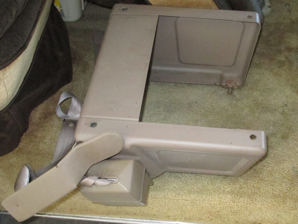
NEW BASE
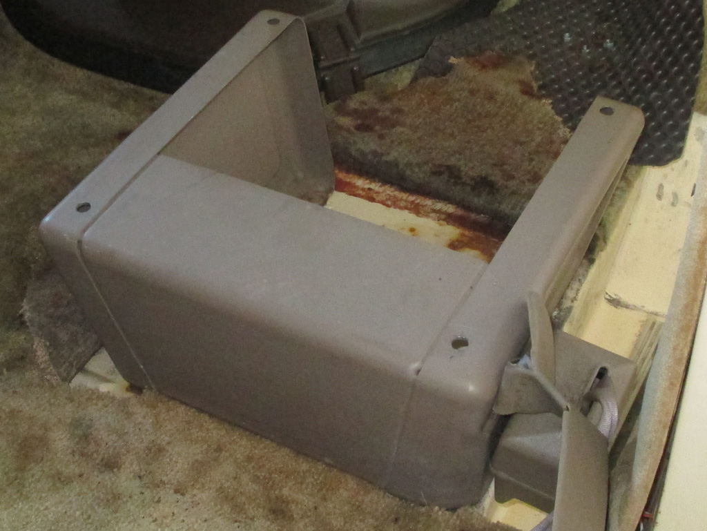
TEST FIT
Turns out I've got a pretty good eye. The holes are in exactly the position they need to be in making this (other than finessing the one sloppy hole), a bolt in swap. I was rather pleasantly surprized, having fully expected to have to drill a couple of holes (and patch those not needed) in order to get this to work.

It's kind of hard to do this job and take photos at the same time. A quick trip to the hardware store netted me some flat washers (of a size I actually did not have), and some lock washers to complete the install. A little hammer work flattened out the two "puckered" mounting holes in the floor of the van. I dropped the base into place, started all four flat washer, lock washer and nut sets on each stud and tightened everything down.
Once that step was completed, I set the actual seat into position on the base and tightened up the four nuts that hold it in place. It really couldn't be much more straightforward than this. A quick shot of upholstery cleaning foam, a little scrub brush and vacuum action and the three or four small stain marks disappeared. Then it was on to the next step.
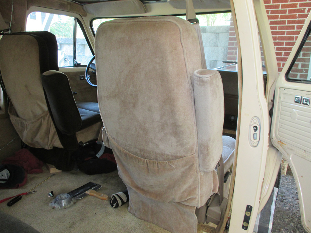
Of course wifey had to give me the business about the new seat not matching (a long-running in-joke about me needing everything to match), but there was a simple reason for that. My original intent was to bolt my existing seats onto the new seat bases which would give me new seat belts in the bargain. But... When I went to install the 1995 seat track onto my original seats, the side-to-side flat steel mounting straps were not far enough apart (front to back), to make mounting feasable. I'd have to cut off the front mounting strap on the underneath side of the original seat, move it forward on the seat frame, then weld it back into place. This was on a Friday afternoon and I wanted to use the van the next day.
Needless to say, my plan had to be modified. That, in a nutshell, is how I ended up swapping complete units instead of my original mix and match intentions. These bases are much more sturdy and the sliding seat track is beefier as well, with both sides having a locking notch feature. My original seat tracks only had one side that latched. The opposite side more or less just followed along. I'll live with the swap for a while and if I like it, I'll have these reupholstered to match the rest of the seats in the van.
I had replaced the original seatbelt with one from a Beauville van with the same interior color. Unfortunately, the seatbelt webbing had cut into the aged plastic rendering the new replacement as useless as what the van came to me with. Thanks Murphy... needless to say, I needed to find yet another solution to this pesky problem.
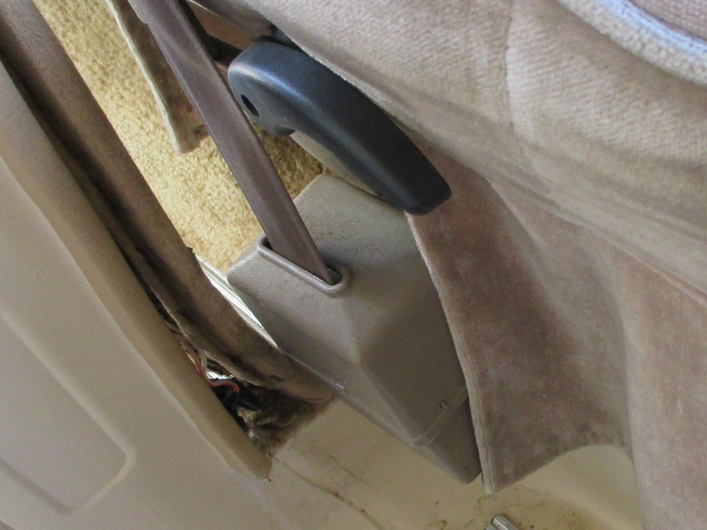
BASE MOUNT
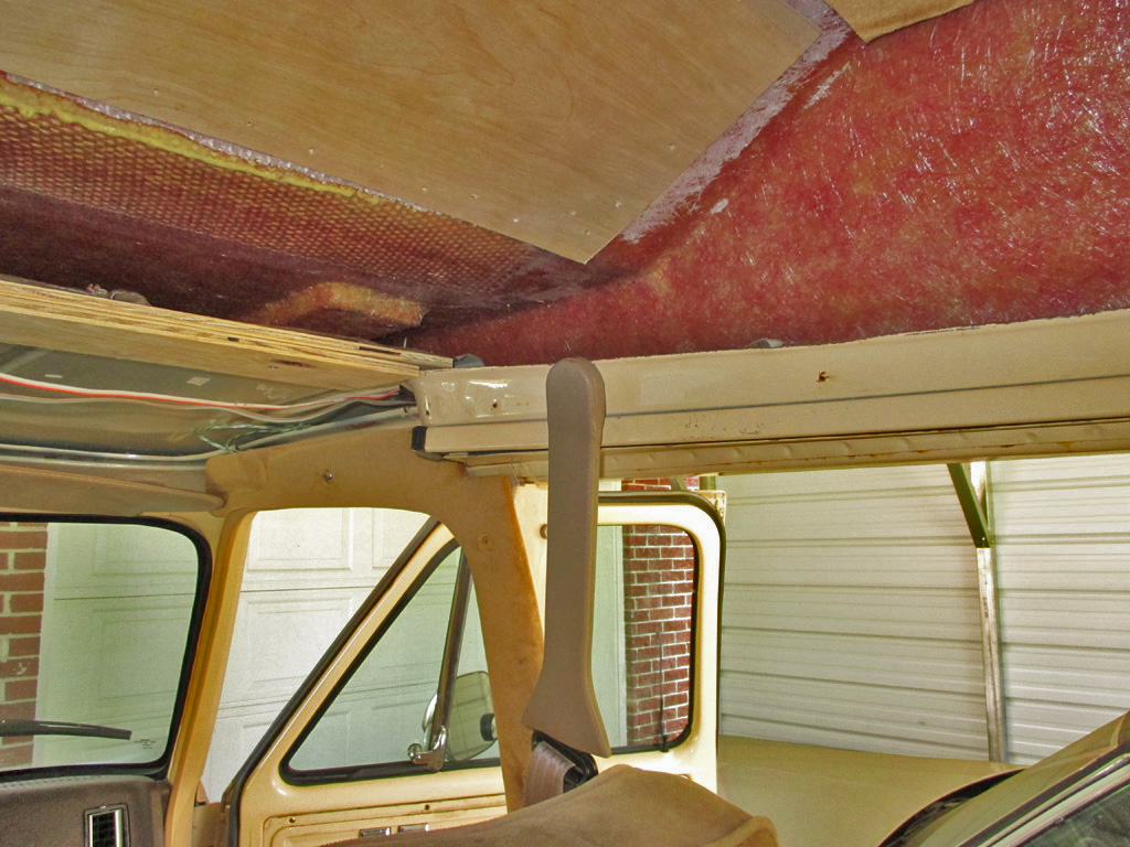
TOP MOUNT
When I ran across these seats out of a 1995 model Chevy with good belts and a driver's side power seat, I grabbed them. Now, for the first time since taking ownership, I'm able to have my passengers buckle up like they're supposed to. Fortunately for me, no one pulled me over before getting to this point.
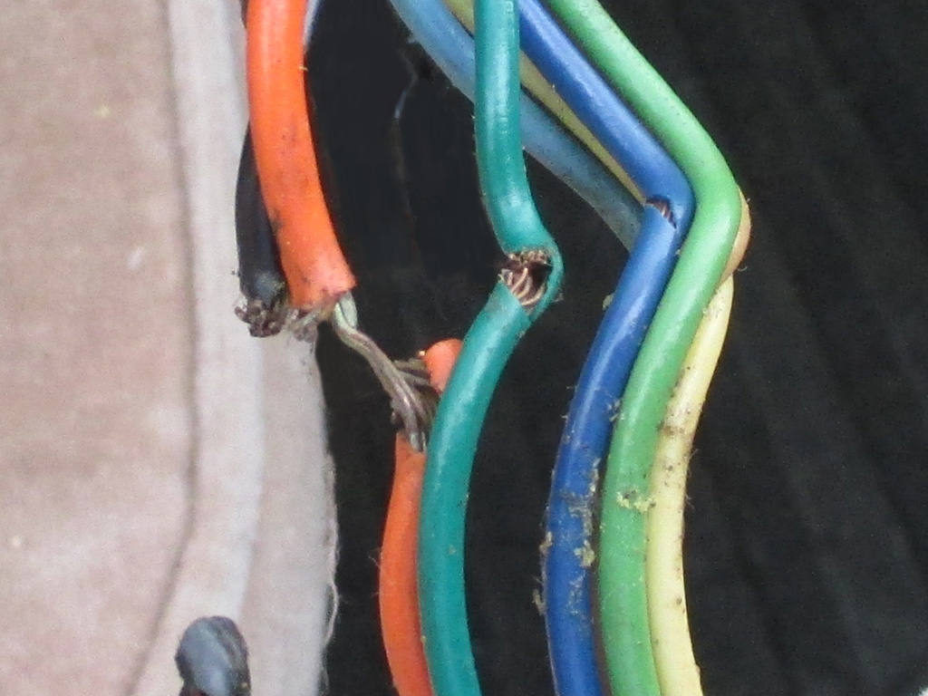
The driver's side power seat needed some repairs before I could install it. When I hooked a car battery to the positive and negative wires nothing happened. But... when I performed the same test on the motors themselves, everything worked properly. I tried to apply power to the switch, but got nothing. I either had a broken wire or a bad switch.
Needless to say, there was nothing wrong with the switch. One wire (the black ground), was completely severed, another had about half its strands cut and a third wire hanging on by two strands. Someday I'll absorb the uses of my voltmeter to determine continuity, but for now I'd found the problem. A little cut and splice action, a little solderless connector repair work and the seat was once again functioning properly.
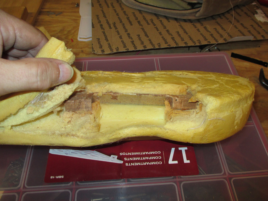
With the wiring issues sorted, it was time to attend to the armrest itself. When I brought the seats home, the switch was attached by a bungee cord wrapped around the armrest two or three times. Upon further investigation I determined that I would need to replace the missing wood if I wanted to be able to restore the appearance as well as the functionality to this seat.
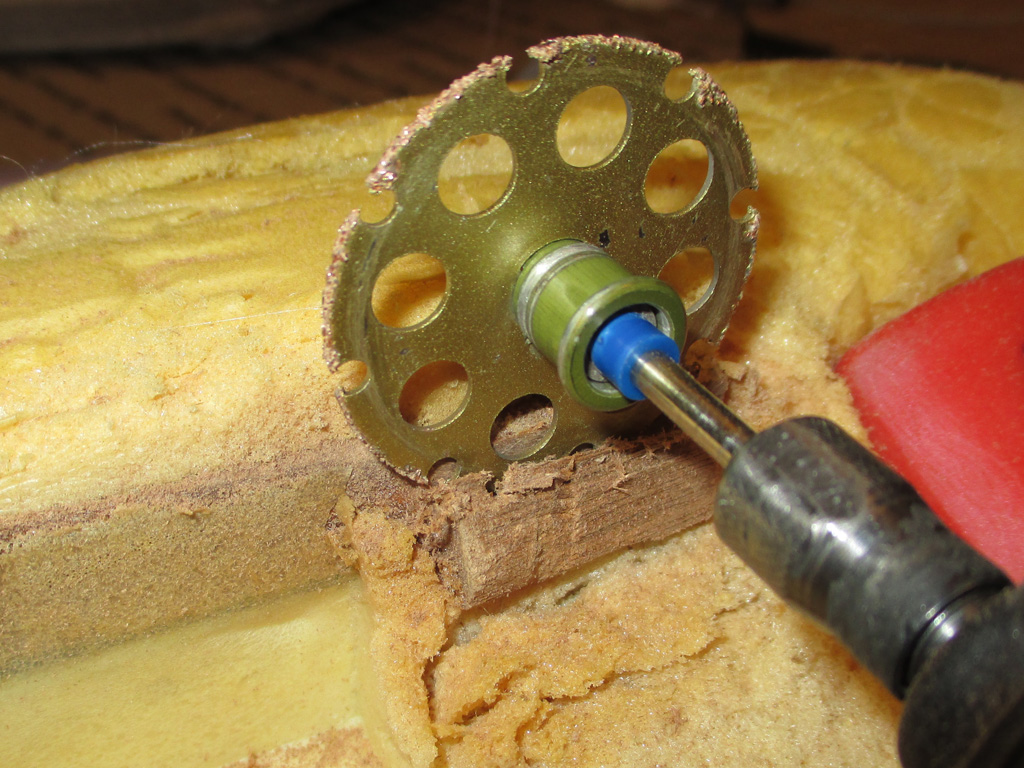
I used some clamps to hold the foam out of the way while I performed surgery. I made my cuts high, because the screw holes would split the wood if I made my seam there. In fact, the part facing the pivot for the armrest had screwmarks in it, so my theory is that the other half of the screw marks are in the missing piece, wherever it may be.
I used some of the oak I had left over from my cupholder project as my repair piece. I had it on hand, it seemed to match what remained in the armrest and I think a hardwood will resist splitting over a softwood. I'd be willing to bet that the company making these seats didn't bother to pre-drill the screw holes either.
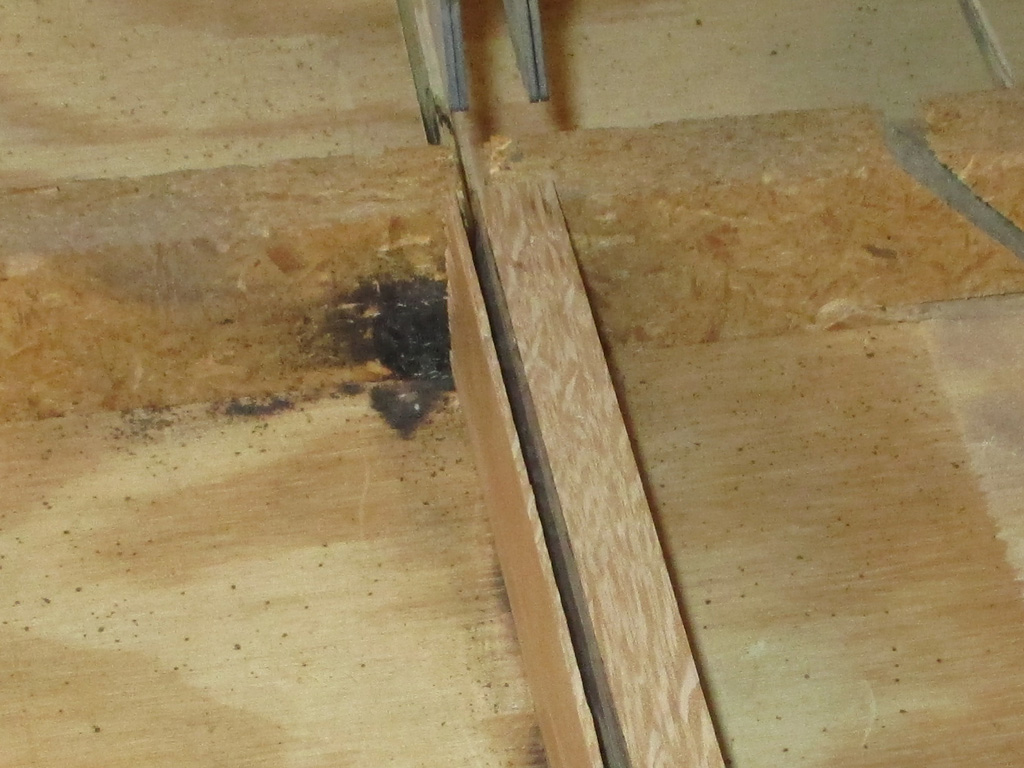
After measuring the thickness of what was in the armrest, I couldn't find anything comparable, so I marked the thickness on a scrap of oak and fired up my radial arm saw. Presto! I now had the thickness needed. I then cut it to the same length as the original wood, cut out the opening with my sabre saw and sanded the old and new until I had a good fit.
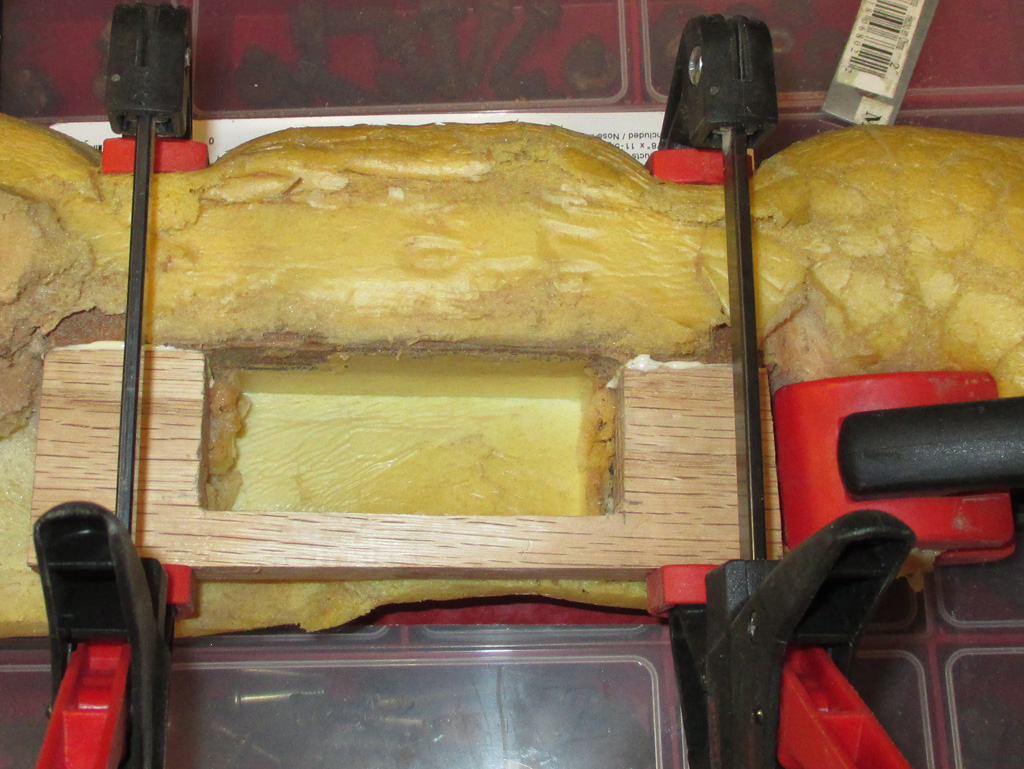
I broke out the Elmer's wood glue and used some more clamps to set the repair. Then I waited 24 hours for it to completely cure. In the past, I've tried to separate two pieces of wood joined with this stuff. The wood split apart, but not where the seam was! For this reason I have a great deal of confidence in this stuff.
I toyed with the idea of reinforcing the repair with some metal, but inside the opening wouldn't work and there was no access to the outside due to the foam. In the end I said "screw it" and went with the glue only repair. It certainly held up as I continued my work.
With the wood replaced and trimmed to the proper dimensions, it was time to re-atttach the foam rubber to the wood. For this phase of the operation, I turned to some Elmer's Contact Cement and I brushed it liberally on both surfaces and let it dry.
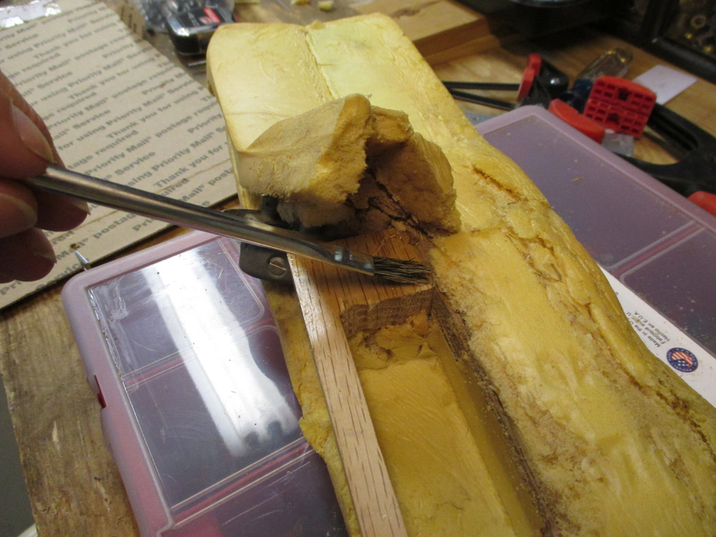
APPLYING CEMENT
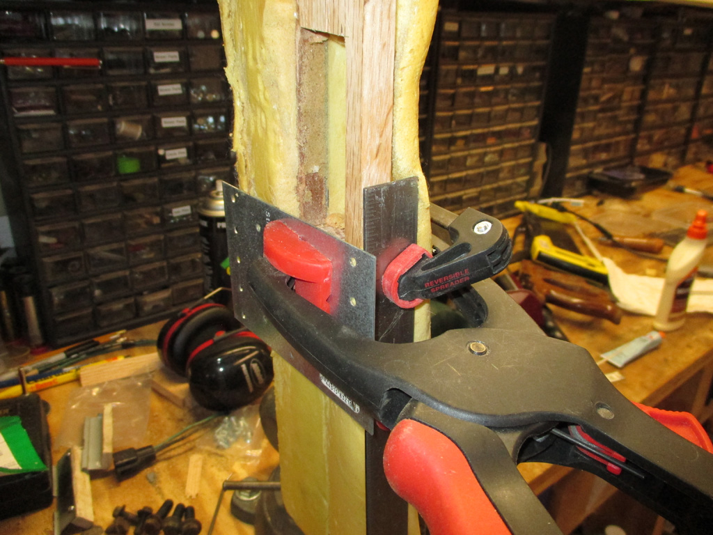
CLAMPING PARTS
I then pressed the foam and wood together, placed the armrest in my bench vise and clamped everything up for 24 hours. I used some thin steel pieces between the clamps and the foam to spread the pressure over the foam and not compress it at one place only.
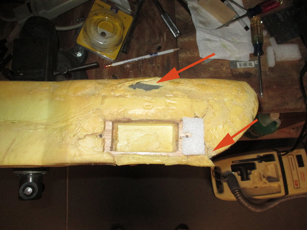
The foam that originally backed up the switch assembly was gone. The foam rubber I had on hand was way to soft and would have allowed the front of the switch to compress the fabric more than was required. I cut up some styrofoam packing pieces that had about the right stiffness, contact cemented it in place and pre-drilled the holes for the screws so I won't split the wood.
Where the arrows are the cement just wouldn't hold, so just before slipping the armrest cover back in place, I used a couple of strips of Gorilla Glue super tape to hold everything in position.
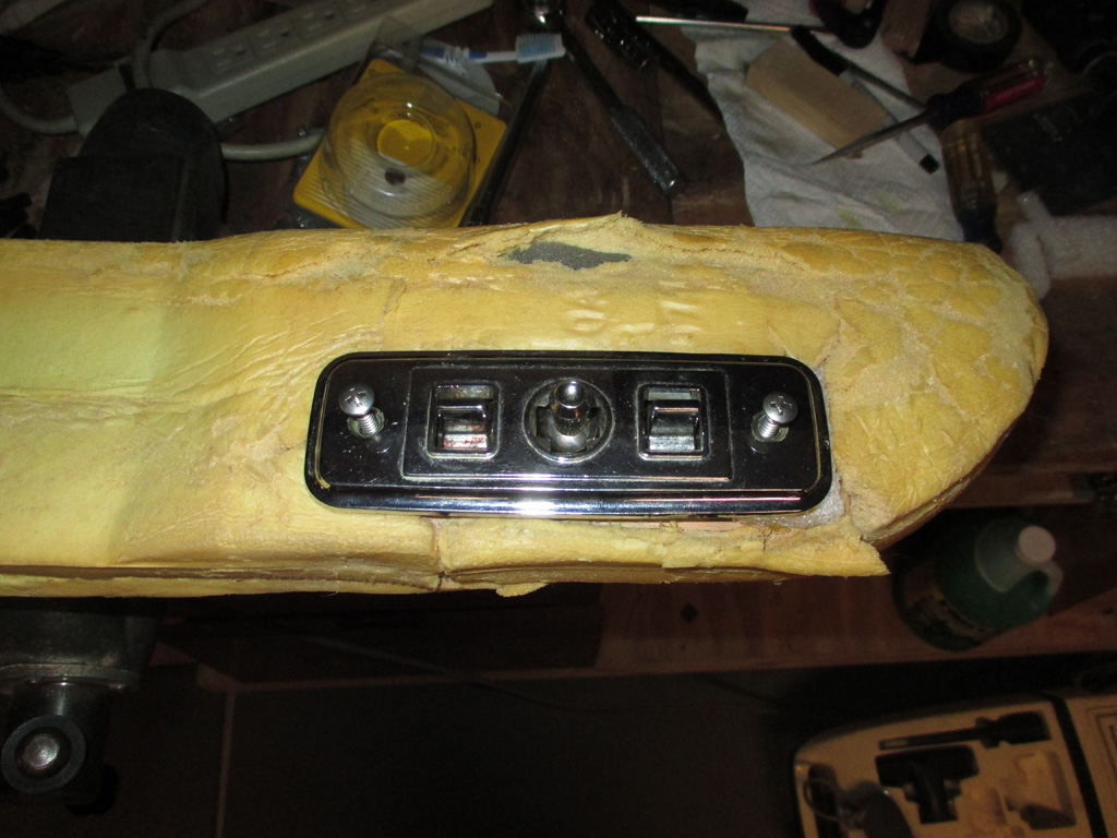
A quick run to the local parts store netted me two #10 stainless screws, 1.5 inches in length. I wanted to make sure that the screws did not pull out of the wood because they weren't long enough. A 5/32 drill bit turned out to be just the right size for the screws. I even went so far as to test the drill bit in a piece of scrap oak just to be sure the screw wouldn't split it. Anal? Maybe. But my repair is going to hold up until its re-upholstery time.
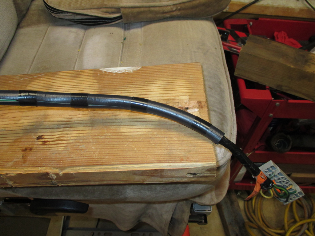
I couldn't feel any sharp edges in feeding the wiring harness back through the opening, but after all this, I wasn't taking any chances. I had some pliable plastic hose left over from a dehumidifier install that was the right diameter for the amount of wires I was dealing with.
The hard part was threading the switch contact plate and wires back through the foam rubber. I also had lots of fun trying to get the armrest back into position, which took some real acrobatics on my part. But in the end I got it back into place.
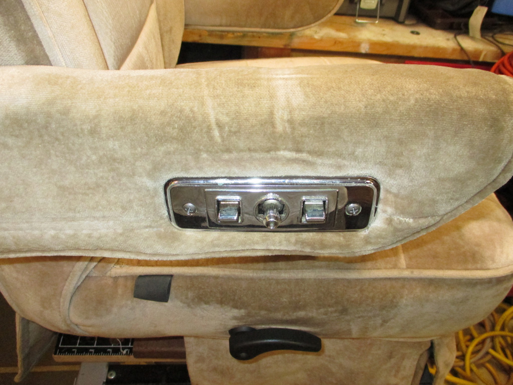
Ta dah! The job is finished and although not perfect (the armrest does sag a bit low), is a far sight better than when I dragged it home. The switch will work, the wires are repaired and protected and I even pried the foam apart (where the bungee cord had compressed it for years) and shoved more foam in there to get rid of the groove on the top surface of the armrest.
Now... now it is ready to be installed in my van. I still have to figure out where exactly to get power from on the fuse block, but my factory shop manual should help me out on that score. Ah, another task completed.
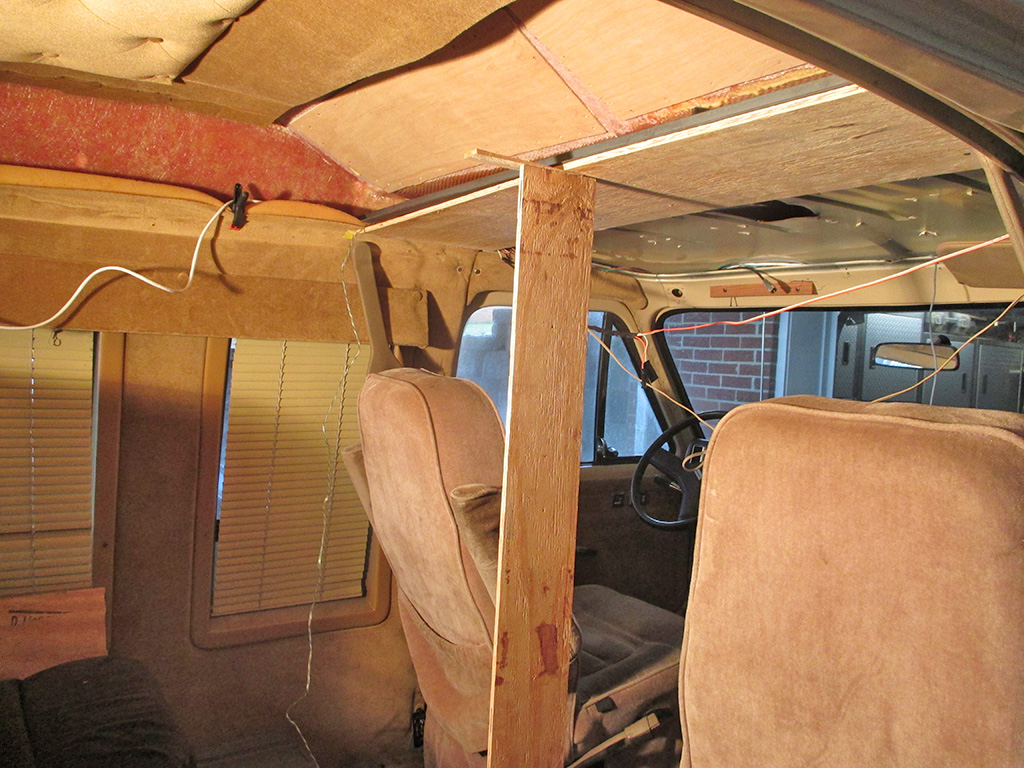
Time to drop back and punt. Since my previously run speaker wires were such an improvement, I ran some 16 gauge 4 conductor wire along each side of the van for the upper side panel lights and the rear reading lights, each fed by separate switches. These ended over the windshield to be tied into my new switch panel. Next, I ran some 2 conductor wire for the cigarette lighters, which will now be used as "power ports" to charge various devices, since we don't smoke. This wire had to be threaded down through the windshield pillar to have direct power from the fuse block. It's the white coiled wire seen hanging over the valance in this shot.
I removed one of my replacement planks which was 5" deep (I cut and installed it before thinking about the flatscreen tv placement), substituting a new 14" deep plank to extend the headliner rearward by 9 inches. This will provide a decent angle for the new flatscreen tv and a mounting panel for the new headliner. It will also provide for installation of a privacy curtain track just behind the seat backs. Now I'm back in the groove!
The deeper plywood section sagged without support, so I installed a 5' length of 1" x 1/8" angle iron (running side to side), to provide a mounting point for the back edge of the plywood. Mounting the angle iron (leveling it front to back and side to side), took the better part of a rain soaked Saturday to complete.
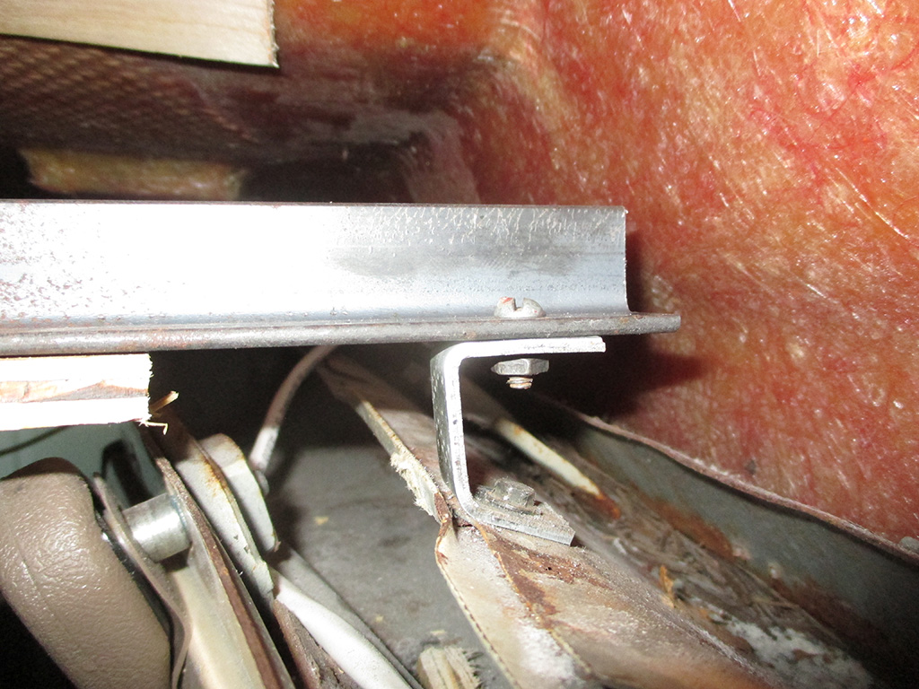
I had to raise the bar (yep, went there) on the right side by slightly more than an inch to get it level from side to side. I bent up a piece of flat stock to fit against the roof and the bar. The place where I drilled through the remnants of the original roof was actually two layers of steel, so I've got a good mounting point there.
I took this shot at the end of the day, so the clamps were as far as I got. I thought I'd be finished much sooner, but many trial fitments and adjustments just ate up the whole damned day. The angle iron will eventually hold a section of 2x2 ripped at an angle lengthwise to support the fascia/surround for the flatscreen monitor I have planned for this location.
It took me awhile to find flat-head screws long enough to go through the wood and angle iron (and had a machine thread so I could use nuts and lock washers) to secure the wood to the bar. I eventually found four of 'em that were the same and cut each to the length I wanted.
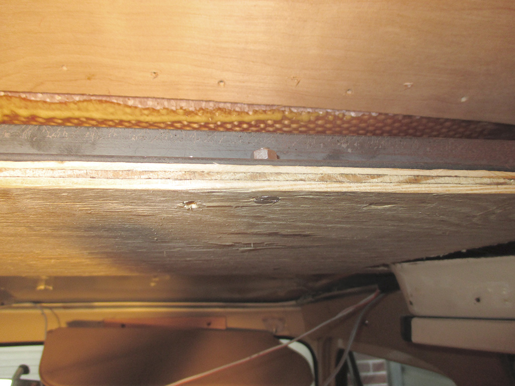
HARDWARE
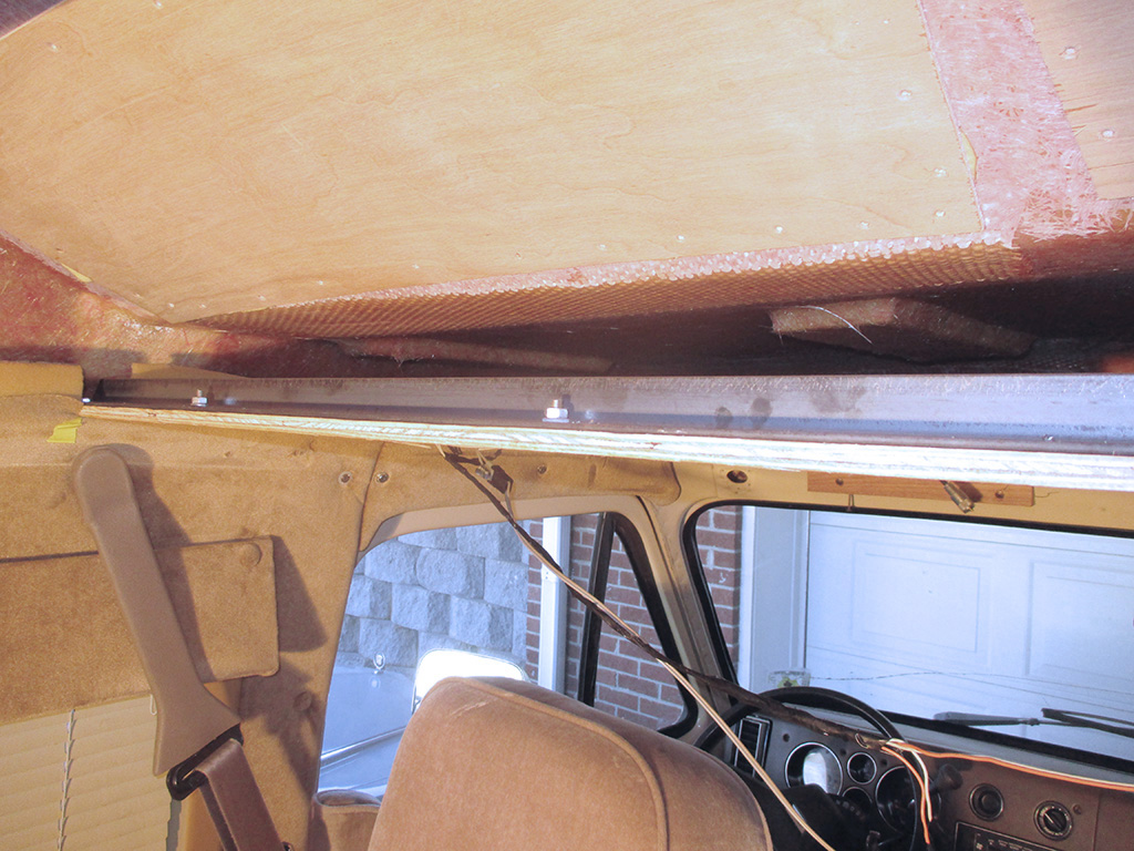
INSTALLED
They're not too even, but you'll never see them anyway. I'll use a spade bit to cut a recess for each screw in the 2x2 which will mount to the angle iron. This makes it easier for me to do this in stages. I suppose you could run a screw through both pieces of wood, sandwiching the angle iron between them if you're really good at this kind of thing.
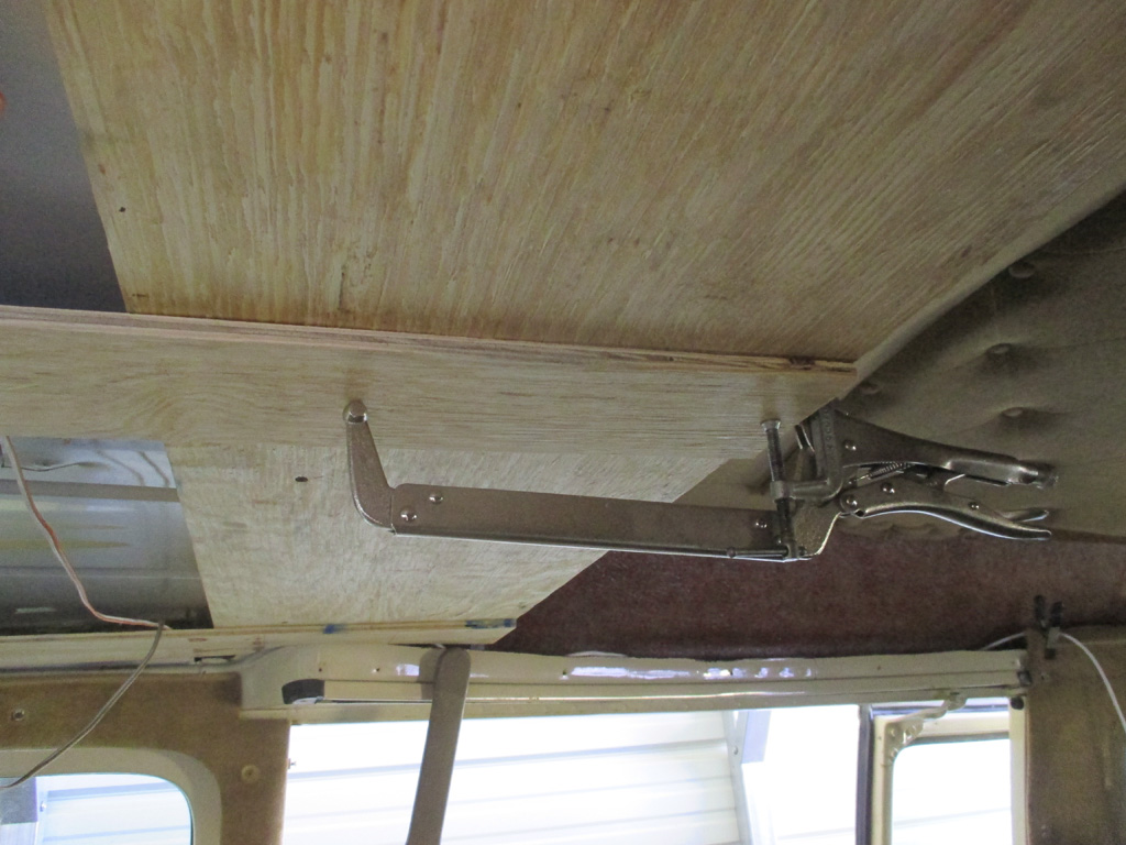
The headliner supports in my van were originally strips of plywood cut and screwed to the original steel roof of the van. Layer 1 got screwed (side-to-side) to the steel, layer 2 was screwed beneath the first layer and the final layer were the 4 strips running lengthwise from over the windshield back to where the steel roof ended. My new design has extended the plywood (as well as the headliner which mounts to it), rearward to suit my needs. The most difficult part of this is to think ahead 2 or 3 steps so you end up with what you want.
With both outside sections cut and mounted earlier, it was time to work on the two inner sections. My deep welding vise-grip pliers served me well in this situation, allowing me to clamp the plywood firmly to the previous layers. An ordinary C clamp worked just fine to clamp the rear most edges together. A few fine-thread drywall screws completed the installation of this strip of plywood.
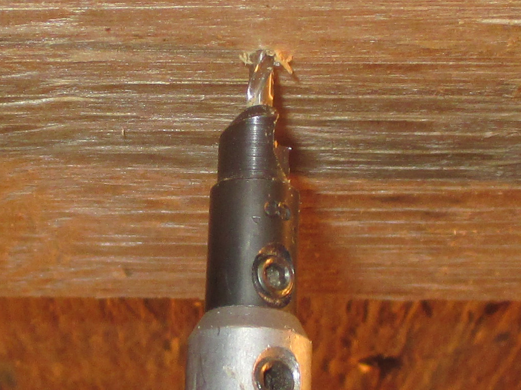
To prevent the plywood from splintering around each screw (all I have to do is look at wood and I get splinters in my hand somewhere), I decided to use my countersink bit. I pre-drill pilot holes for all the screws I use in projects like this anyway, so not a big deal to use the same technique here. Is this necessary? Nope. Just my method of being efficient, since stopping to pull splinters out of your fingers isn't much fun and eats up more time than using this type of tool. Besides it sits in my drill bit drawer anyway, so why not.
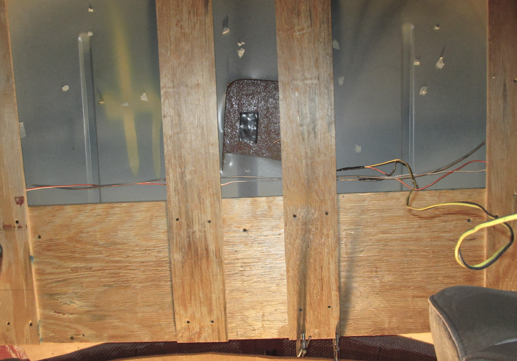
By the end of the day I thought a progress shot was in order. If you were a mole looking up at my work, it would probably look something like this. The four strips of plywood run from the rear edge of my new headliner section forward to just above the windshield, just as they were when my van was originally converted. The only difference is my extending things rearward by 9 inches, which required these strip to be lengthened by the same amount.
I used a roofers square to make sure each strip of plywood was as straight as possible. That means that when they installed the high-top, they really did cut a skewed hole for access to the roof antenna mount. From what I can see, I'd say they used an air chisel to make this opening. Judging from all the other rough, jagged, bent-up edges on the roof of my van, I think they used the same method to remove the rest of the steel too, everything looks like they used an industrial sized can opener on the poor thing!
Cup Holder
Building A Better Cup Holder
November 2013
Although it seems like I'm attempting to establish a new level of haphazzardness with the work I'm doing, there is a method to my madness. The first couple of outings pointed out several shortcomings, one of which was that the two factory indentations in the doghouse intended as "cup holders" are ridiculous. Having removed the Quail Creek Custom Vans unit, I now had to hold a drink while I drove so it wouldn't topple off onto the floor. Time to fix that.
My van came equipped with a bi-level cup holder, cobbled together from 3/4 plywood, formica (actually a good surface choice) with long stove bolts sleeved through chrome tubes. For what it was, it wasn't terrible, (although the two red steel pivoting holders couldn't be used if drinks were in the lower cup openings rendering them useless), but had been crudely screwed to the engine cover/dashboard beneath the radio completely covering the flip-up door which concealed the lighter and ashtray. I want to use that area for my equalizer and some 12 volt power ports. The bi-level cup holder had to go.
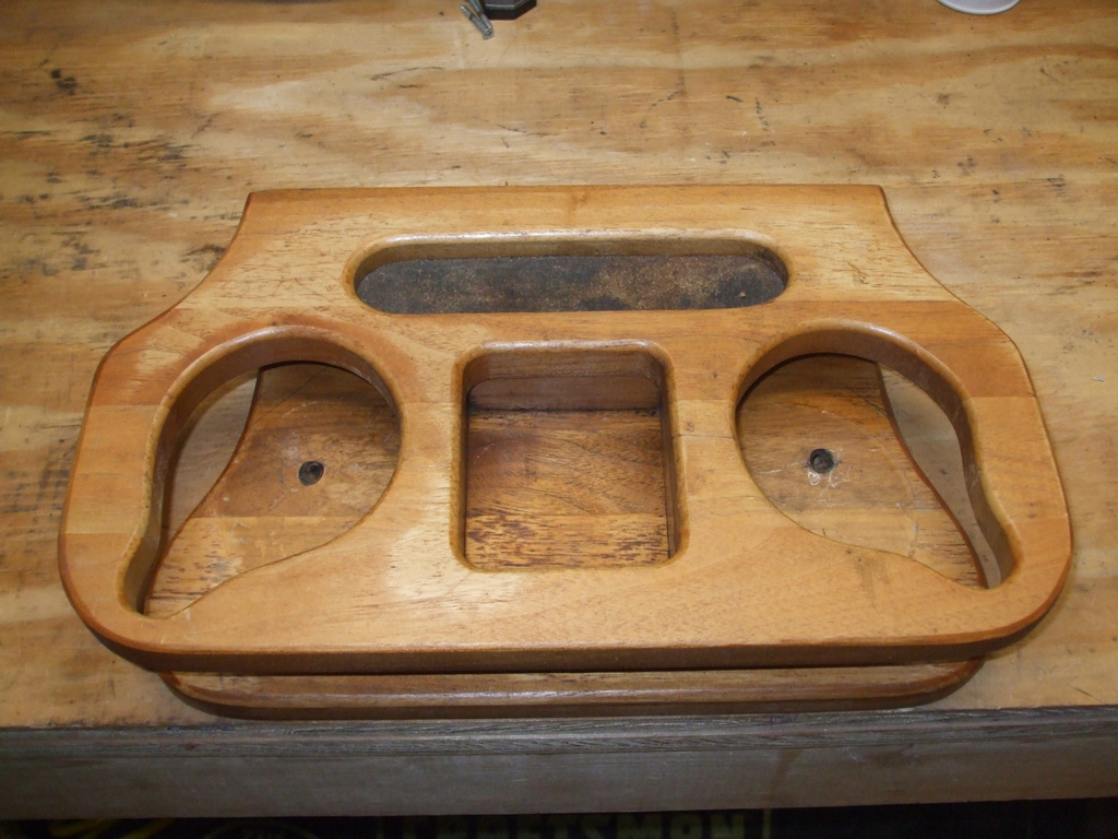
SALVAGED UNIT
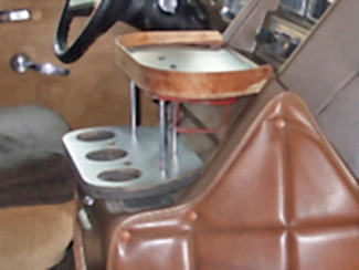
QUAIL CREEK
I salvaged a more refined looking (solid red oak) cup holder from a van another guy was parting out. It wasn't perfect either, but it wasn't so ungainly that it blocked the stock dash accutruments. By measuring carefully I hope to have a usable unit that will fit in with what the factory supplied, not cover them up.
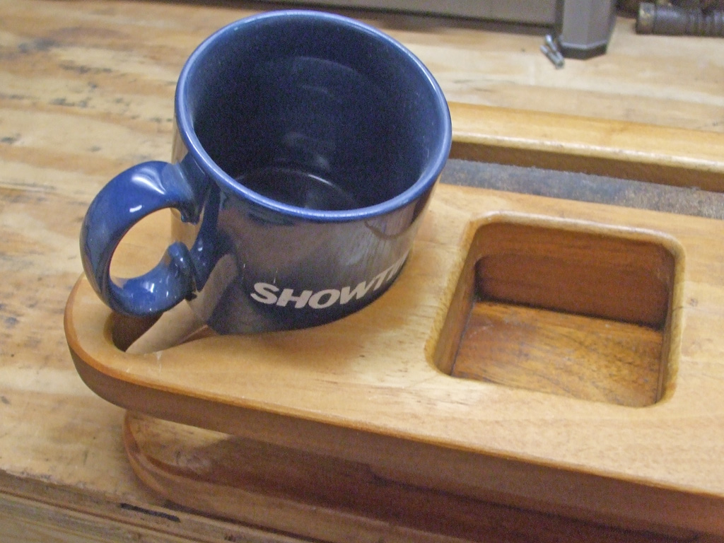
Step one... evaluate just what I have to work with here. To that end I decided to see if an ordinary coffee mug would fit into the round openings. The result actually struck me as quite funny. As we can see here, the new unit failed this part of the test. However, in all my years of driving, I've never once attempted to use a household coffee mug while on the open road.
Water bottles, soda bottles, BIG GULP cups... sure, lots of those. Since drive through coffee typically comes in some sort of cup, I'll rig something different for actual coffee mugs at a later date. My goal for this little project will be to make sure the most frequently used drinking vessels will fit in this holder.
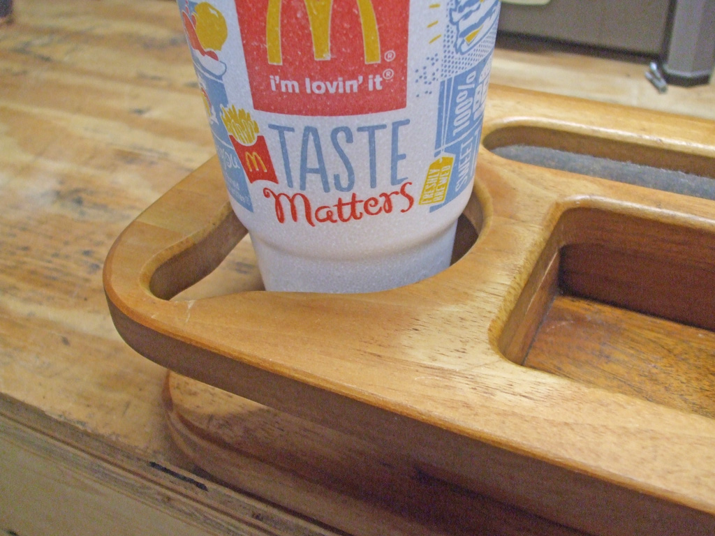
Whenever I'm out and about, styrofoam cups (for both soft drinks and coffee) seem to be what most vendors sell you. Since I just happened to have one laying around from a recent trip to Mickey D's I figured I'd use it as a model. The salvaged cupholder I'm using as my template, just doesn't measure up. The narrow base of the styrofoam (plastic ones do the same thing) is too narrow for the holder to secure properly.
However, all is not lost. This is where I get down to work and start modifyin'. What I need to do is raise the top of the unit (by means of a taller center section) and I'll have just what's needed for my van to be drink-friendly. A quick trip to the big orange box store netted me a remnant cut from a 1x12 red oak plank which I'll use as my new wider base and taller center section.
After carefull measuring (eat your heart out Norm), I was confident that I could duplicate the original lengthwise cut. I've found that my radial arm saw is the perfect tool to accomplish such tasks. With the saw unplugged for safety, I measured and aligned everything just so. Then the moment of truth as I made the cut. Pretty anticlimactic really. 5-10 minutes making adjustments and all of 20 seconds or so to make the cut. Some guys can achieve results like this with a Skil Saw (amazing to watch them do it actually), or Miter saw, but until I bought the radial saw I couldn't cut straight for a hill of beans. Results like these make me feel like a real woodworker.
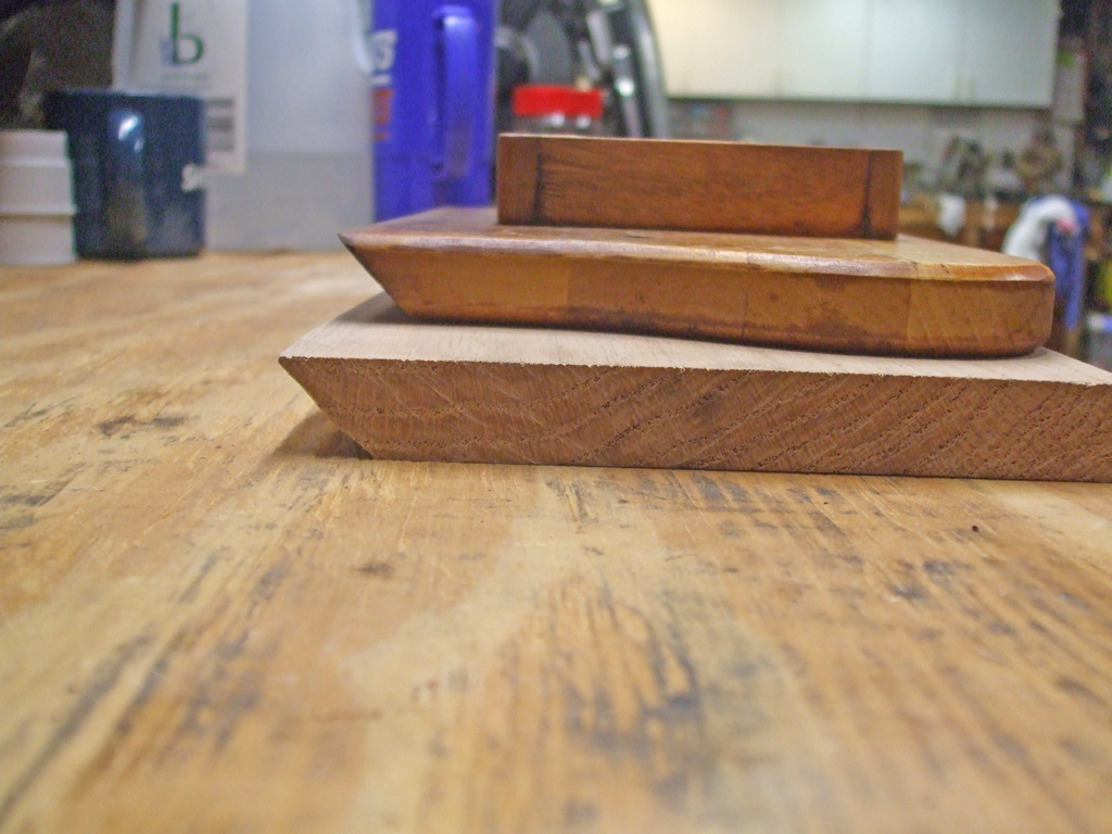
ONE 45* RIP CUT
TWO 90* CROSS CUTS
So one 45 and two straight 90 cuts and I had the blanks I would be using for the next few steps. After measuring using the styrofoam cup and a stack of various thicknesses of wood, I decided that 2" would be ideal. After cutting the blanks into smaller pieces, I discovered the new height just clears the flip up door whre the ash tray and lighter are located. I held the four pieces together with a rubber band, sandwiched them between my new base and original upper and somehow it worked out perfectly. I don't think I could do it again if I tried. Sometimes you get lucky and Murphy's busy messing with someone else!
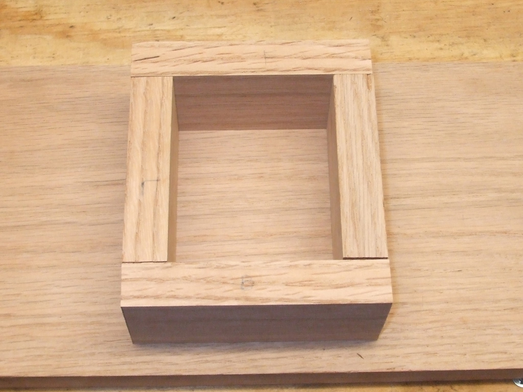
I must say I continue to be impressed with the precision of cuts I am able make on my radial arm saw. Some guys can pick up a circular saw and make straight accurate cuts with it all day long. I've seen it done. I'm not one of those guys.
I copied the measurements of width and depth from the original center support, only the height will be different. It's been said that a poor artisan blames his tools. I believe that the opposite is also true... proper tools are necessary to produce professional results.
I may not be building a baby grand piano here, but I still want the end result to look professional. Not only that, but the wood itself (even though I purchased a remnant) wasn't cheap at $15 bucks.
Those who've given my site more than a passing glance will notice that I despise the outsoursing of tools and parts that's taken place over the past couple of decades. Far from simple nationalism or discrimination, the "pacific rim" sourced items simply do not do the job. I took extra care to pre-drill all the holes beforehand to prevent splitting the wood.
I wasn't expecting a trip to bent nail city!
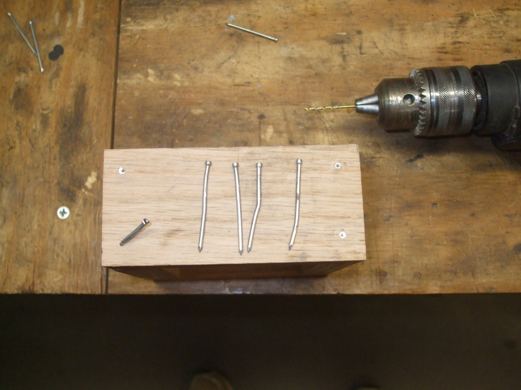
CHINESE NAILS!
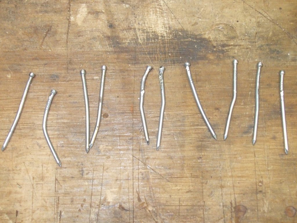
THE CARNAGE
What I hadn't counted on was the inferior metal used in the production of the nails themselves. I only needed 8 nails to complete the task at hand. After bending 12 nails (and the ensuing damage to the wood through the repetative nail removal process), I was getting exceedingly hot under the collar. I ended up losing a few of the bent ones to the slamming of the hammer and pry bar on the workbench. Later, I noticed some of the nails I was taking out of the box were already slightly bent! Made in China tools and parts suck!
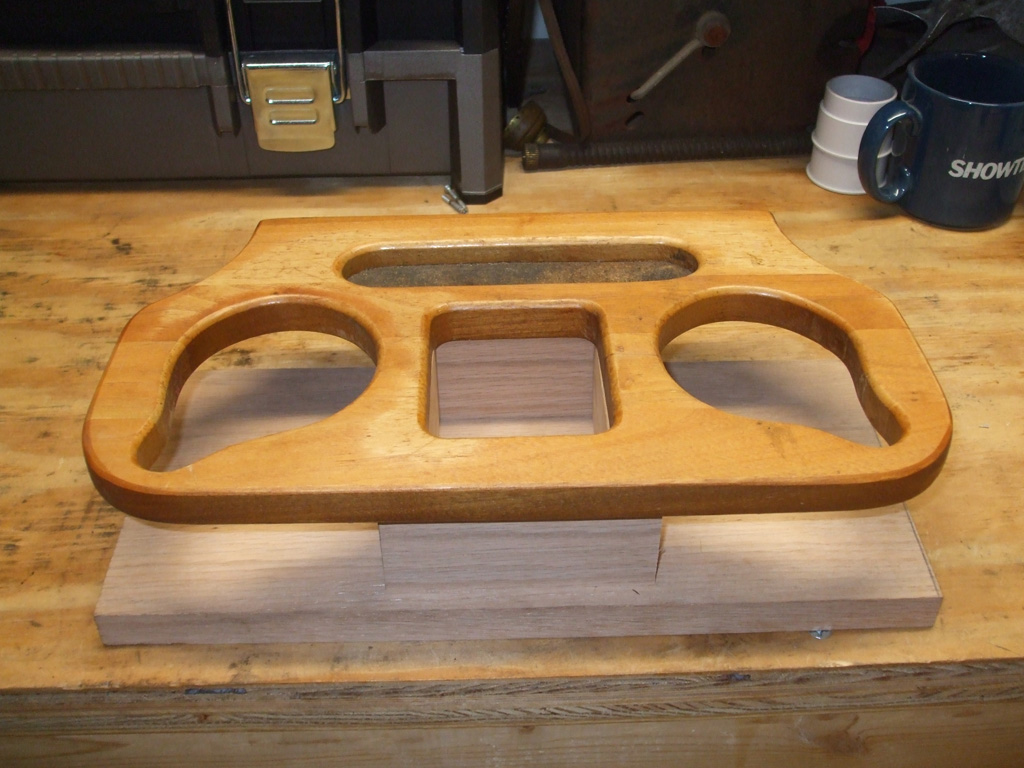
I was eager to see how my modified cup holder would look, so I set everything up in place just for a look-see. At this point I still have to remove the cork (used as a pen/pencil tray I think), which will also be replaced with new cork. I thought about repurposing the slot to hold electronic devices, but decided the center area would serve this purpose. Besides, who wants to hunt for a writing implement when you're traveling?
With the new center riser section in place, it was time to check the fitment of various cups to see just how much I'd achieved with this modification. The upper wood section now accomodates a styrofoam cup, gripping the wider section of the base of the cup. This should keep the most frequently found cups in place without tipping.
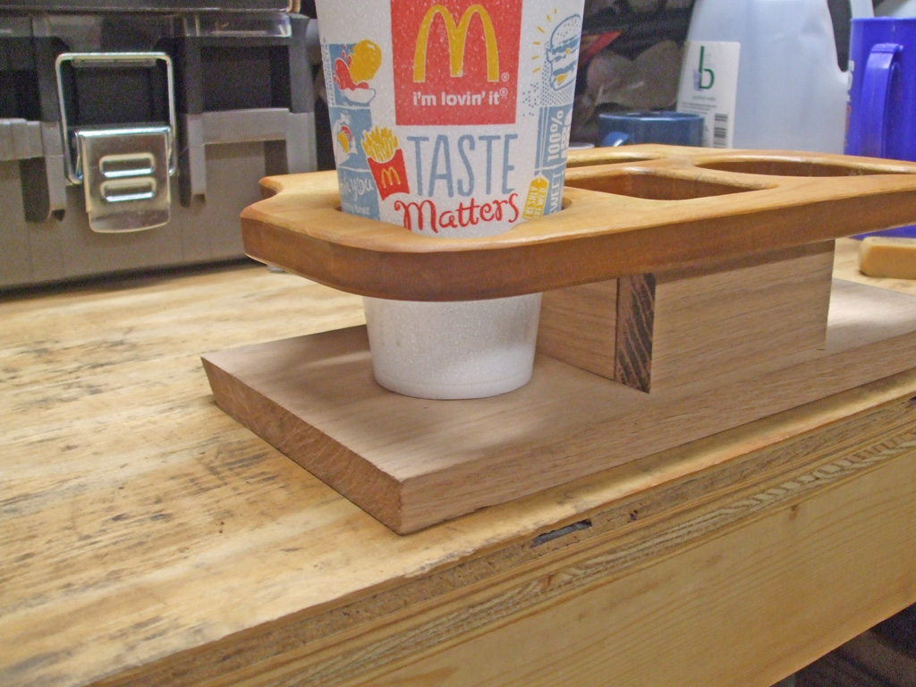
STYROFOAM CUP
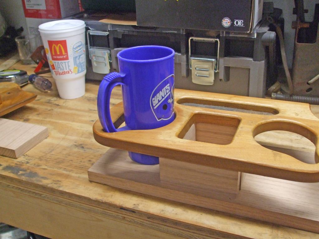
PLASTIC MUG
I also had an old plastic sports mug sitting nearby and decided to see how it fit. The circular opening doesn't grab the cup, but the mug handle cut out works as designed. I thought about enlarging the circular opening to accomodate a coffee mug, but the increased height now makes the "ears" of the mug un-grabable. So in the end it will be a compromise as to what drinks will occupy the new cup holder.
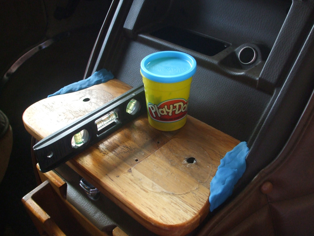
Moving right along, it was time to turn my attention to the new base I am creating. My first idea had been to make the base piece wider so I could install some sandstone "thirsty" coasters in the wood, so when the cup sweats it won't damage the wood. Even though the polyurethane will protect the wood, the water will make a mess and I want this to be a more professional arrangement than the conversion company could produce.
Here I'm using some Play Doh to see how big a gap I have to fill with the new wood. Easily moldable, the Play Doh allowed me to make a mold of sorts, which I can use to trace the new outline onto my new piece of oak. I used the weight of the can to help me keep the original base plate level as I made my measurements.
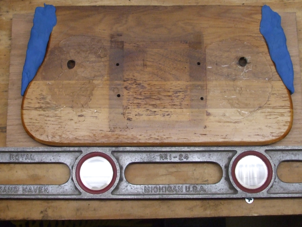
I used a level as a straight edge to align the new base with the original to make my tracings. Although the Play Doh put me in the ballpark width wise, it still took several measurings to get the measurement I needed. I don't want to make this an exact fit, because it will take me forever to cut out the square-edged notches that would require.
My goal instead is to make a more "square shouldered" base which should give me enough width to use the coaster idea. The original base was polyurethaned also, but you can see where repeated use was starting to wear through it. This is what I hope to eliminate with my new design.
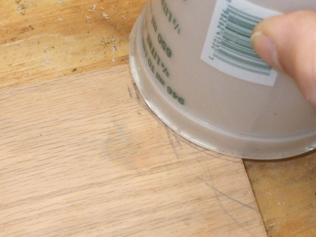
One trick I learned along time ago was to use circular objects whenever I need to draw a circle or an arc as seen here. After figuring out that a simple arc was going to be a lot easier for me to craft, I decided to use an arc to clear the indentations on the vans doghouse.
For this part of the process I used my reciprocating saw to make the cuts I needed. Of course I'll need to finesse these later, but for now it'll put me in the ballpark.
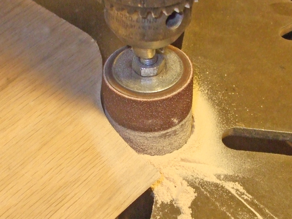
If you don't have access to a drill press, clamping the wood in a vise and using a hand drill would give me the same results. The only difference is the job is a lot easier and I can be much more accurate using the drill press. This part of the process took me quite awhile to complete, as I had to sand a little, take it out to the van and test fit the piece, then return to sand as required.
Not only did the process take time but I'm also dealing with a hardwood here, so that's to be expected. Hard to tell just how long this took... I'll guess a couple of hours. When you're "in the zone" it's difficult to be a clock watcher.
After wood gluing (and nailing) the center riser, I rounded off the outside edges using the 80 grit drum sander followed by some 220 grit on my palm sander. As the pictures illustrate, I've roughly doubled the height, which enables the upper circular openings to support the common as dirt styrofoam cups. The center riser itself will make a convenient holder for an iPod or smartphone that needs charging. At least that's the plan at this stage of the game.
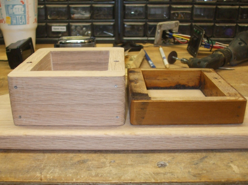
NEW RISER
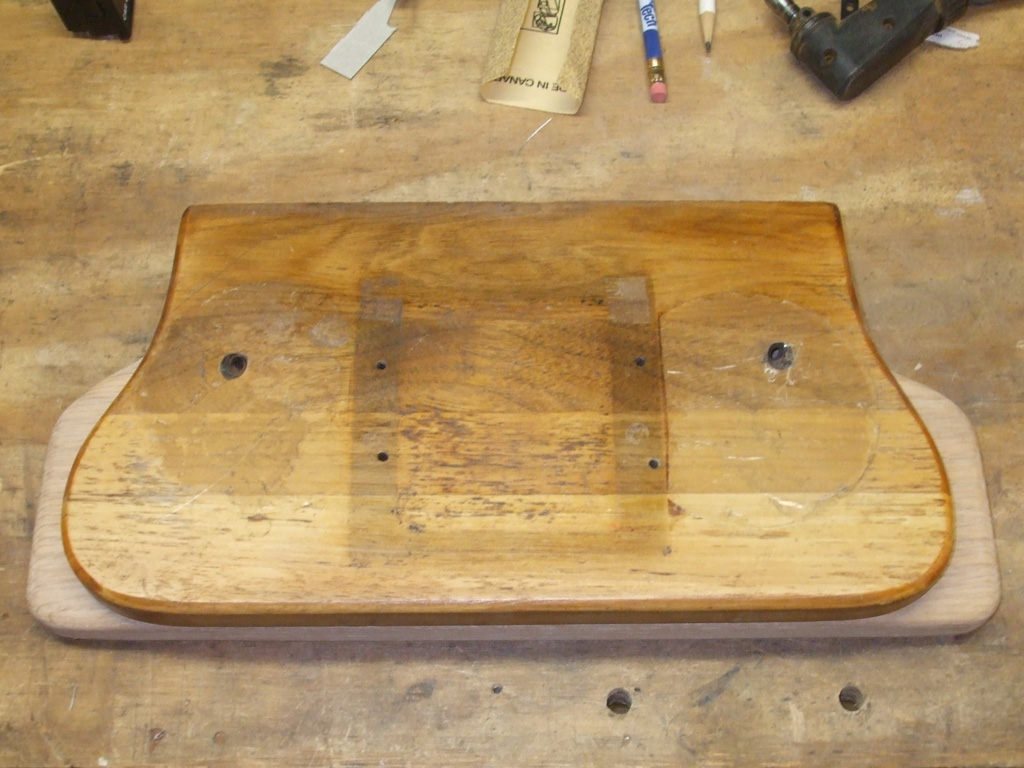
NEW BASE
The new bottom plank is a little wider and more squared off than the original. It was a tough decision not to make the bottom so wide you'd hit your knees on it when installed, but wide enough to hopefully use my built in coaster idea. Other than the width, all the other dimensions are the same. If I made it any deeper, access to the factory flip down glove box would be difficult, so I had some restrictions to deal with during this re-design. Even so, I think my new version will suit my needs much better than the one the van came to me with.
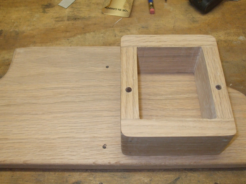
The original short riser had two screws going through the bottom board, the riser itself and then into the top board. My new and improved riser is way too tall to run a screw through, so I had to devise another plan to fasten everything together.
Two screws will still come up through the bottom board and into the riser, not through it. The top of the riser will be doweled and glued to the bottom of the top board, eliminating the need for screws. My goal here was to keep all the fasteners hidden.
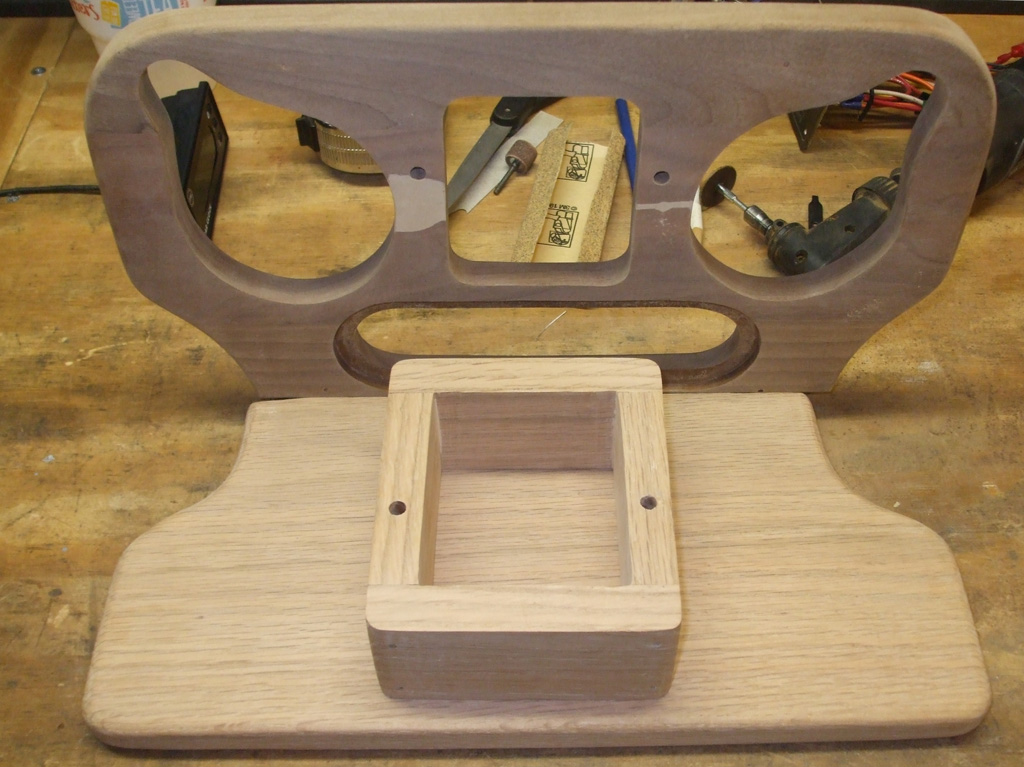
The underside of the top board actually had two splits in it (glued together by the time I got the van) one was where a screw had gone into a knot. Then I got anal retentive and filled the two damaged areas with Plastic Wood, which I then block sanded flush. I'll stain the area that's seen (virtually hidden bottom edge of one circular cup opening) with some tea to make it blend in better before applying the polyurethane.
I sanded the old finish off using a 100 grit 5" disc sander in my 'lectric drill, followed by some 220 grit in my palm sander. The inside radii were handled with my trusty Dremel, equipped with an 80 grit drum sanding attachment. It was some pretty tough stuff I have to say. When I'm all done I have some new polyurethane to finish things off with. I enlarged the original screw holes to the size that matches up with the dowels I plan on using, since they were pretty much centered anyway.
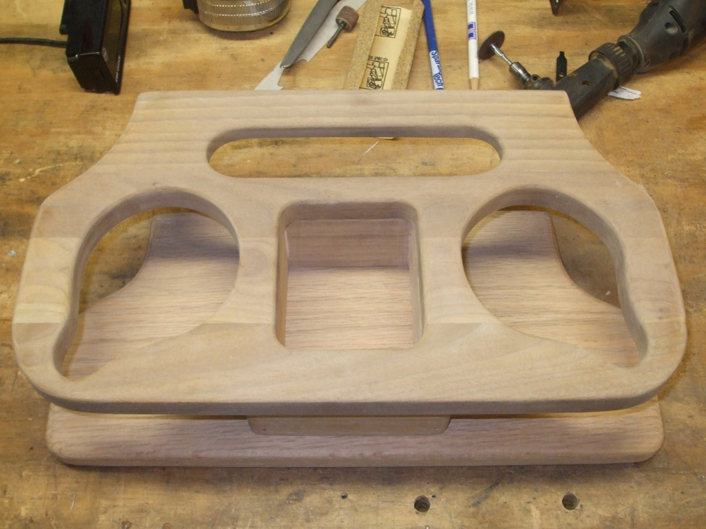
Ta dah! Hours of sanding later, I'm finally ready to add my polyurethane finish to the cupholder. My original "recessed coaster" idea has to be modified. I don't have the necessary tools to machine such a recess into the face of the bottom board, and the coaster itself will come very close to the edge of the board where it curves in to miss a vertical extrusion of the doghouse surface.
I may try to use some contact cement to hold the coasters in place instead, but that'll have to wait until I'm finished with this phase of the operation. I still plan on using the coaster idea, but I'm going to have to modify it somehow.
Cha-Cha-Cha Changes
February 2014
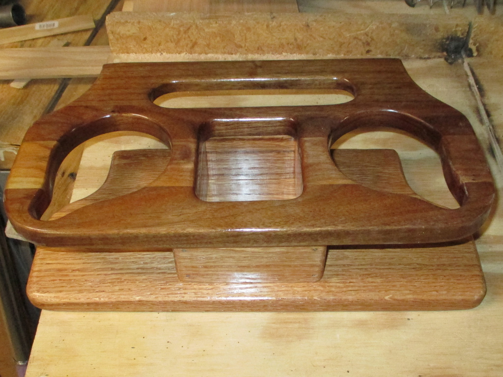
Ta dah indeed. Once I had everything sanded and polyurethaned I noticed a problem (two actually), that I just couldn't let go of. The upper level of the cup holder didn't match my new lower shelf. I mean it wasn't even close. I would later learn it was a piece of Honduran Mahogany, which sounds exotic but against the red oak it looked like crap. You know what this means.
Yep... back to the big box store for another section of red oak (this damned cup holder's getting pretty expensive at this point), with which to fabricate a new upper shelf. It's probably for the best anyhow. I can remake the cupholder using the original as more of an inspiration rather than an exact template. The cork-lined oval depression at the front isn't wide enough for a pencil, so that will be the first modification I make.
Probem two? I'll also need a new slab of oak to re-make the bottom shelf, so I'll have room for my "thirsty stone" coaster feature. This way a sweating cup won't be setting directly on the wood. I have re-configured the top shelf so the cup holes are further apart to line up better with the built-in coaster idea too.
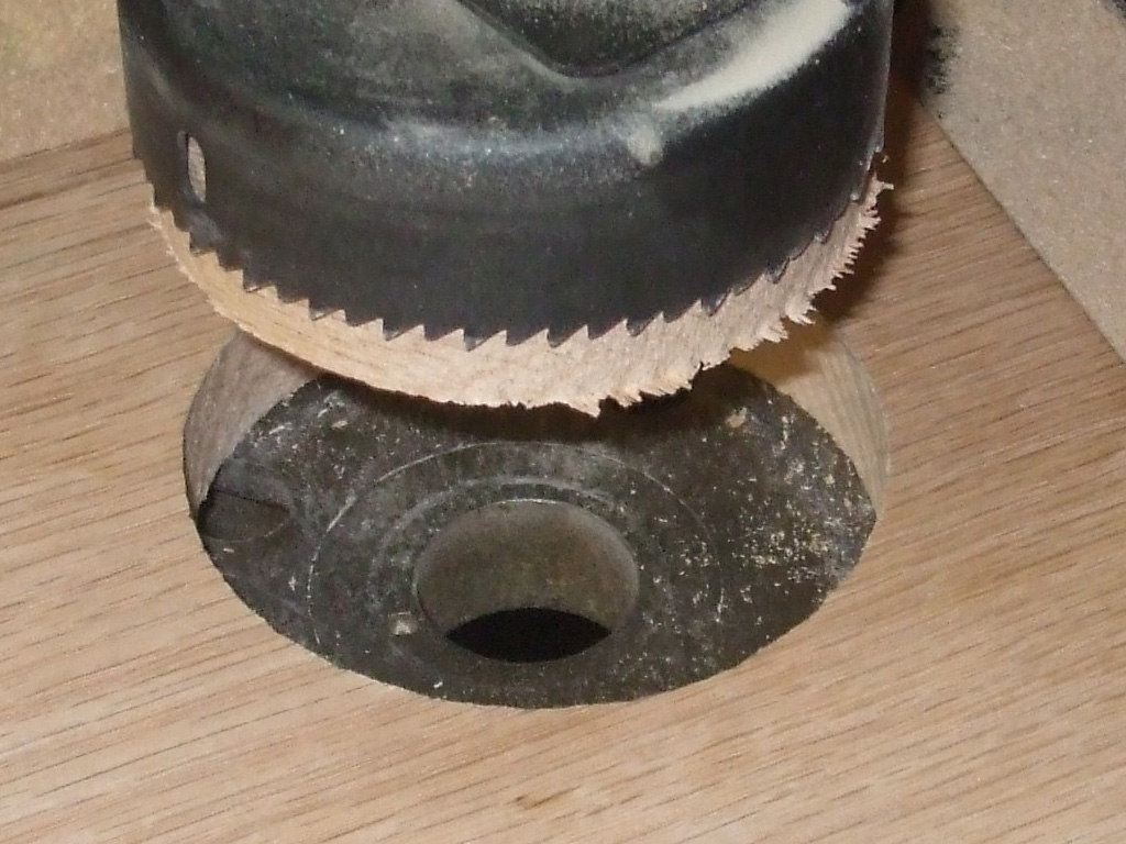
After much measuring and planning, I made the new upper shelf about an inch wider than the salvaged unit. I also made it deeper so I can move the cup openings back about 1 1/4 inches. I also made each opening 5/8 inch wider than the old unit. This will let me move the coasters on the lower shelf back and further apart, so they have more wood around them for strength. This just goes to show that perfectly round holes aren't that hard to make... the holes on the original unit being anything but.
This means the lower shelf will be wider also, though not quite as wide as the top shelf to cut down on knee whacking issues. I can't make the lower shelf much deeper or I won't be able to open the stock glove compartment, whose knob is right below the shelf. Not quite sure how I'll address this little issue, perhaps a cutout in the wood for knob access? At any rate . . .
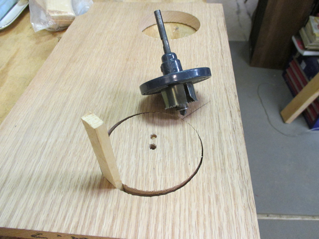
With my two new cup holder holes completed, I was left with a bit of a conundrum. How to make the second (coffee mug handle) opening to mimic the original unit. I don't have a bandsaw and my efforts with a jigsaw are laughable at best. So the idea came to me that I could use a smaller hole saw, overlap the first hole (using only half of the circular saw blade) and end up with a near perfect half circle cut in the wood.
But... How exactly can I do this and prevent the inevitable tear out? The idea I hit upon was to make use of the circular scraps and tightly wedge them back into each hole. This would give me a "solid surface" to make another hole in and prevent damage to the wood. At least that's the plan at this point.
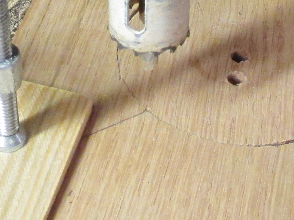
With three slivers of shim wedges tapped in place with a hammer (and trimmed flush with a hacksaw blade), I was ready to rock and roll. Here I've got everything clamped in place and took this shot just before making the cut. I don't know that this will work, nobody showed me how to do this, I just came up with the idea on my own.
So I've got 'er all clamped down, measured and re-measured and the time finally arrived to flip the switch on the old drill press. I suppose I could have tested my idea out on a piece of scrap pine first, but I didn't want to take the time to do all that. So, as someone once said... "and away we go!"
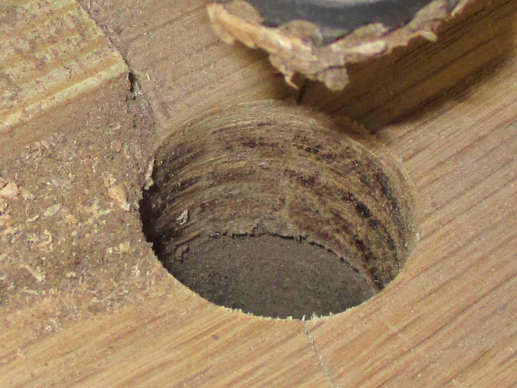
In the end, my little plan worked out perfectly. I was able to make my two overlapping cuts without any tearout. I probably should have switched to a lower speed on the drill press (the wood was smoking pretty good from the friction/heat), but didn't want to spend the time monkeying around with the drive belt.
With my idea verified by this successful little adventure, I pulled everything apart and set up the other side exactly the same way as the first. While I was at it, I rotated the handle holes inwards, to prevent leaving the wood too thin on the outer edge as on the original unit. In the end everything turned out just as I planned it.

As with a great many other things, there's a lot of prep work involved, then suddenly a minute or two later, it's done! The original cup holder I was using as a template (of sorts), obviously had all the openings cut out freehand. Since I have circular hole saw blades, I decided to put them to use cutting these out.
I ended up with just a bit of tearout along the top edge of one hole. Since the original had the openings slightly chamfered, I don't think this will be an insurmountabtle problem. The next part will be to duplicate the cork lined recess of the original cup holder top plate.
I must confess that the next step had me baffled. The original top shelf of the cupholder assembly had a slot cut out to provide an oblong recess, probably used for pens/pencils or what have you. At any rate, I wanted to keep this detail as it reflected the way things were done when my van was built back in the day. This meant I had to duplicate the slot in the new top section I'm fabricating The burning question though was... how?
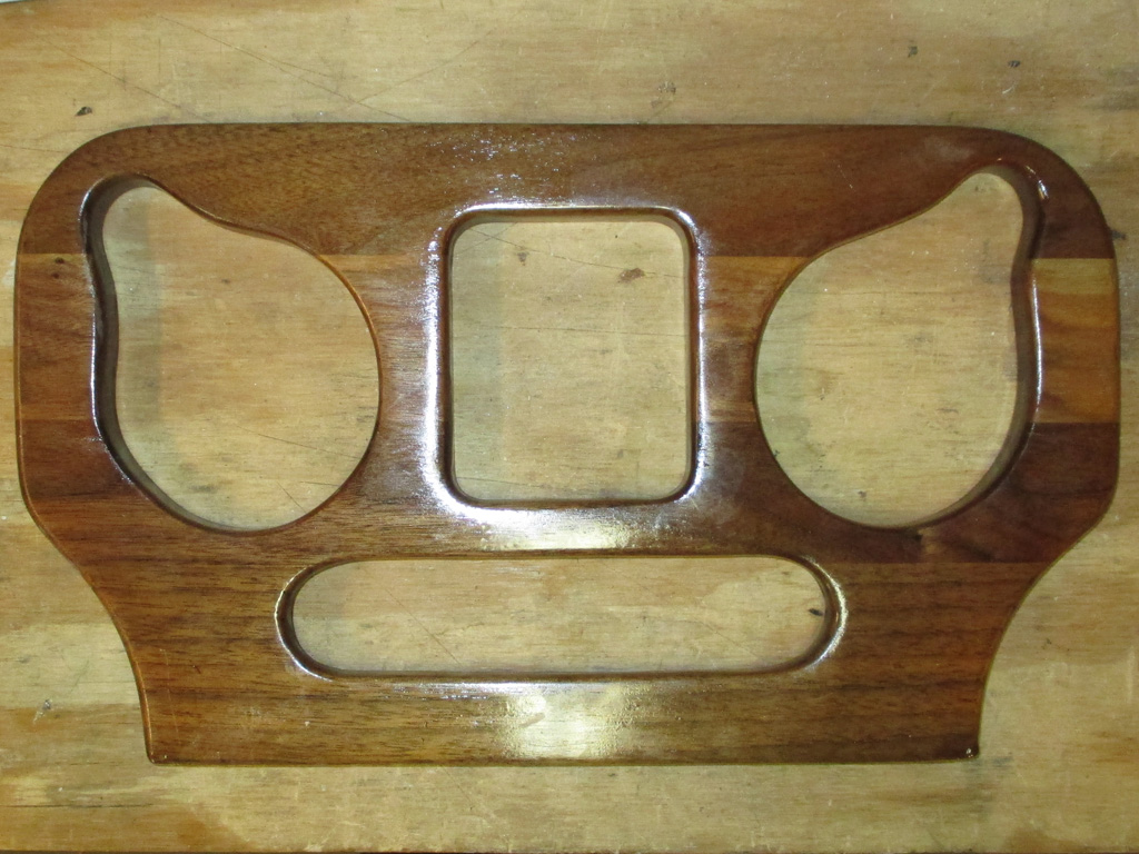
ORIGINAL TOP
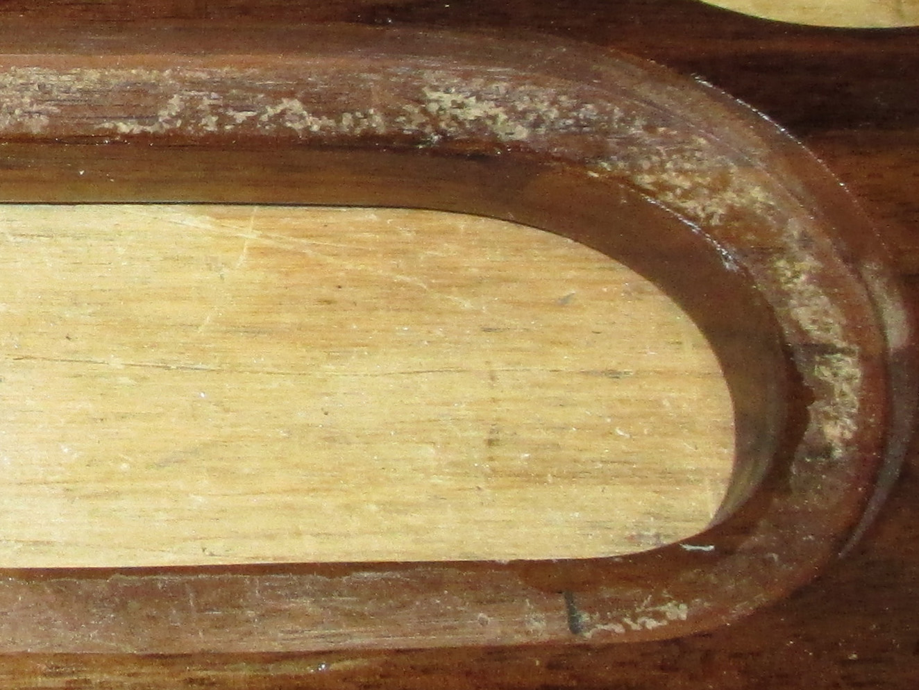
OVAL DETAIL
It seems as though they cut the basic oval shape (probably by a guy who's good with a jigsaw), then flipped it over and used a router to cut a recess for the luan insert with cork glued to the top of it. This resulted in the oblong, cork lined recess. To duplicate their process, I would need a rabbeting bit (which I don't have) and a router (have but haven't used in eons) to achieve the desired results. The more I thought about it, the more I came to the conclusion I wanted to duplicate the effect, not necessarily the exact process. This made me start thinking of alternate methods to achieve the same results.
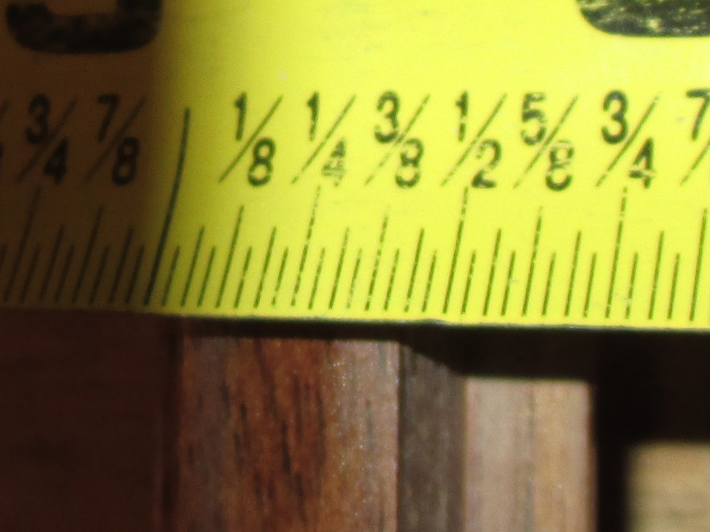
Not the easiest thing to get a shot of, nonetheless I tried. The original slot in the top section was 3/8ths of an inch deep. I also measured the width which came out to 6 inches even. With the measurements written down on a piece of scratch paper I now had a starting point.
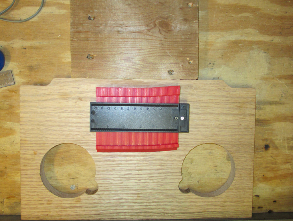
The easiest way for me was to find an object that was 6" wide and center it between the outer edges. My contour gauge happened to be the perfect size for this and happened to get centered at 4.5 inches in from each side.
Wrong... all wrong. I got ahead of myself yet again and failed to take into account that the original design wasn't wide enough for your average pencil (at least not one that hasn't been worn down to a nub first), so I would later end up widening this by the width of the forstner bit on each side.
Over eagerness notwithstanding, my solution to recreating the original oblong recess was to make use of a Forstner drill bit. The advantage of using this type of bit is the resulting flat bottom of the hole you are drilling. When measuring the original, I found the width of the oblong recess to be 1.5 inches, so I purchased a 1.5 inch Forstner bit. By using the depth gauge built into my drill press, I was able to set the depth of the drill bits penetration into the wood precisely.
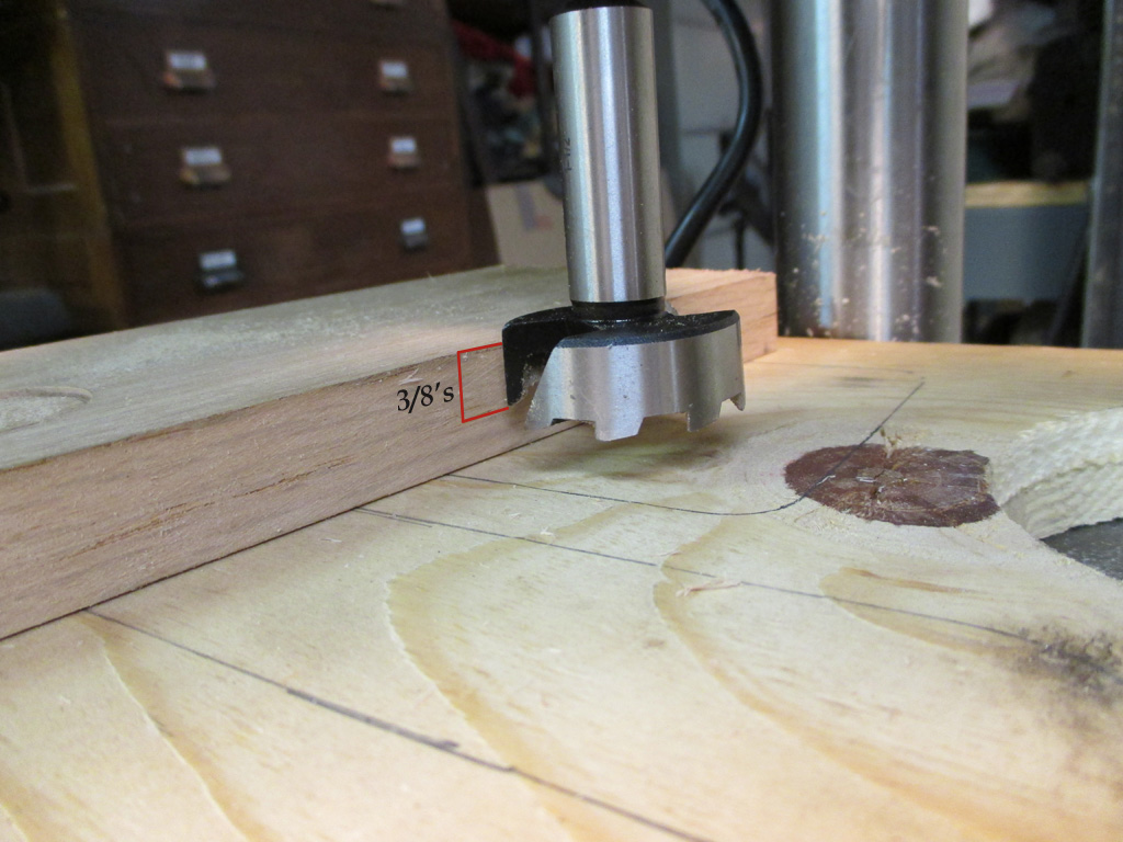
DEPTH INTO WOOD
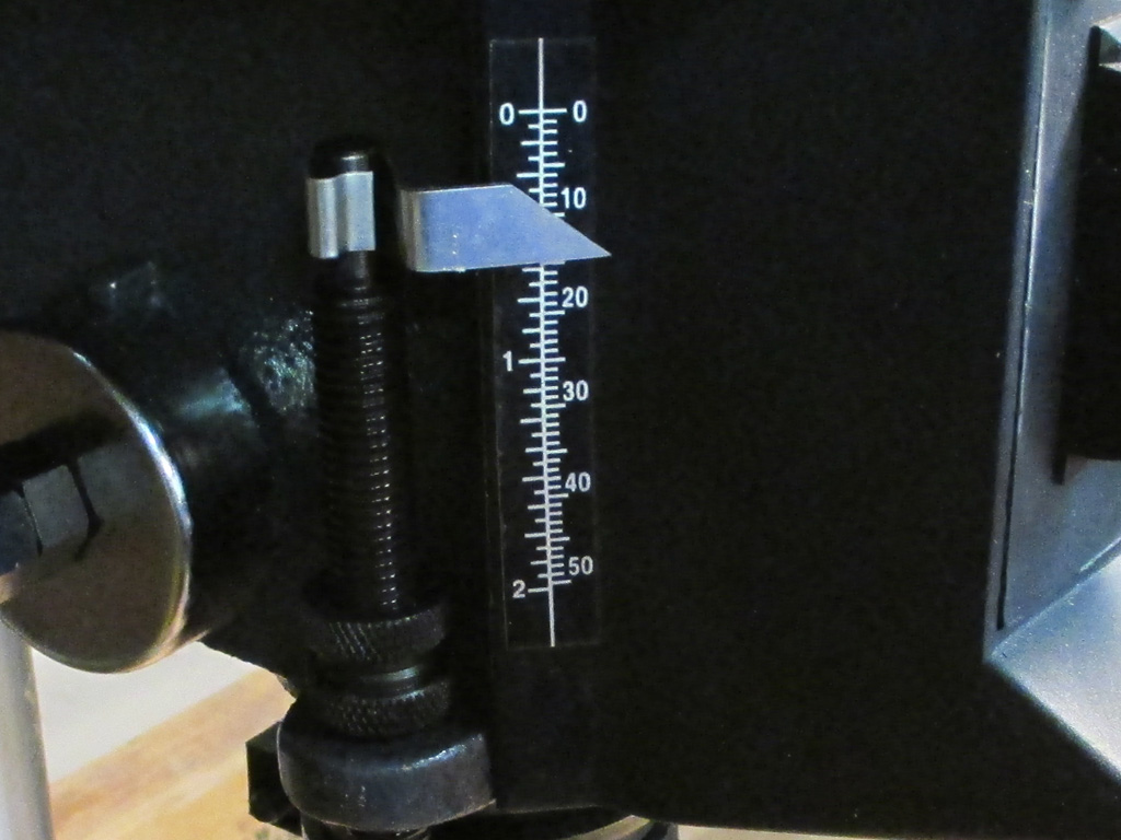
SETTING DEPTH GAUGE
I placed a scrap beneath my workpiece (just in case) and raised the work table of the drill press so the drill bit was just above the wood. This part of my setup took the longest. The wood is expensive, I've already got my other openings where they need to be, a mistake at this point... well, let's not go there. Let's just say I measured way more than twice and set up extra work lights so I could see what I was doing.
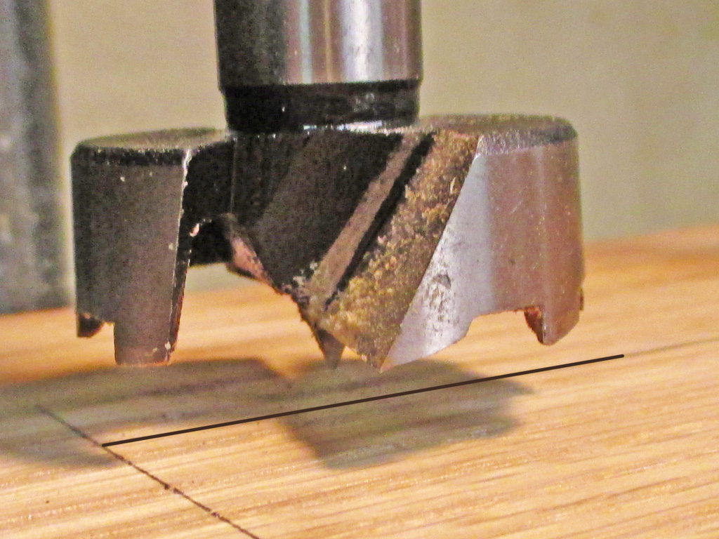
There are probably many different ways of accomplishing this task, a plunge router being the first to come to mind. Not being a woodworker by trade certainly has its limitations, but having some of the proper tools and a pretty good idea of how to go about this drove me foreward. That and the fact that I really want to get this done so I can drive my van in relative comfort.
The original unit's slot had a center point of 6.25 inches in from the rearmost edge. I thought that was too close to the cup openings, so I used 6.75 inches measured in from the rear edge of my new piece. With my 6 inch width marked and my center point established, all I had to do was set up my drill press and start drilling.
By choosing a drill bit the exact width of the opening I needed for my recess, I'd already taken care of one dimension. My width marks and center line mark took care of the other measurements I would need. I made sure the outer edge of the drillbit lined up with my width mark and then made sure that the center point of the bit was exactly on the center line.
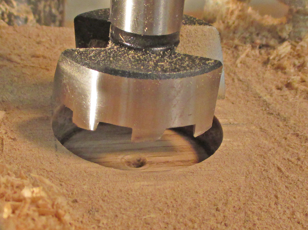
FIRST HOLE DONE

OUTER HOLES DRILLED
So... what's the reason for drilling the two outermost holes first? Simple. I've got this nice new Porter Cable drill bit (MADE IN CHINA... AGAIN!) and hey... it could go dull and stop cutting at any time. This way, if the drill bit crapped out I had both curved outer edges done and could use some other method to remove the necessary wood between these two end points.
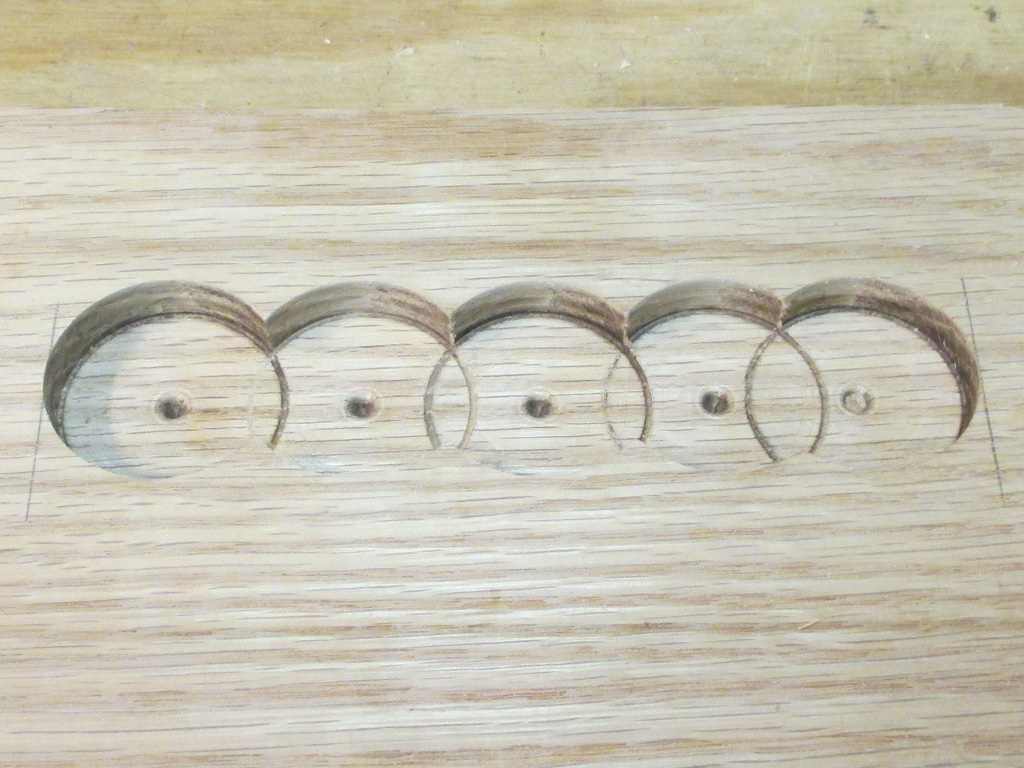
Amazingly, the drill bit held its edge and was cutting as good when I stopped as when I began. Quite frankly, I was stunned. Good thing... since my plan required drilling five overlapping holes to create the oblong recess in the wood. This way I would have a recess with a flat bottom, rounded edges on either end and only some small triangular sections needing removal at the end. Since the recess will be lined with cork on the bottom, the holes left by the bit will never be seen.
It took a couple of holes to fine tune my technique of drilling, backing off for a second or two, then drilling some more. Oak is a hardwood and even though I set the drillpress speed for wood, it did generate a bit of smoke as I went. At one point I had to hold the wood down with my left hand (couldn't get a second clamp to hold securely), and the wood shavings hitting my hand were hot! I only stalled the drillpress once, so there's a bit of a learning curve doing this.
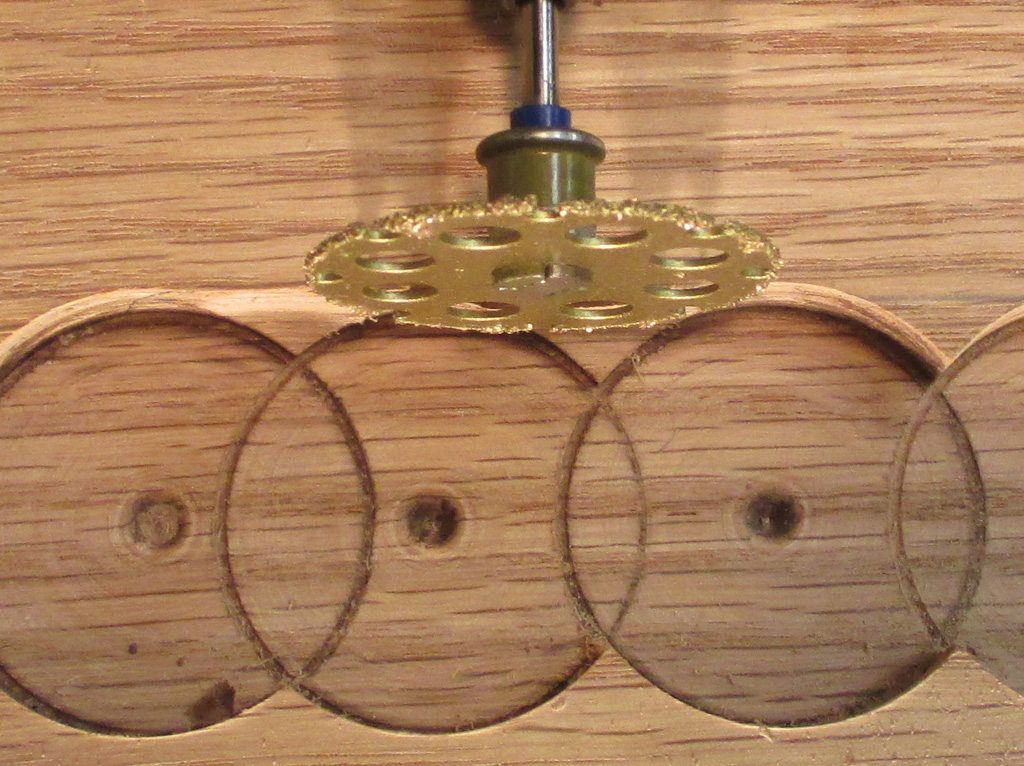
After ruminating over how best to remove the remaining wood pieces, I decided to spend some cash and buy a special carbide wood cutting blade for my Dremel. I hated spending just shy of $20 bucks on such a small thing, but I need to get the job done and I can use the blade for other woodworking projects. So I bit the bullet and bought the thing. Again, this was just my way of doing things.
If I'd had a oscillating sander (the kind that takes optional flat flush cut blades), I'd have used that instead. For me this was about the cheapest way to go and I didn't want to split the wood by using a wood chisel so there you have it.
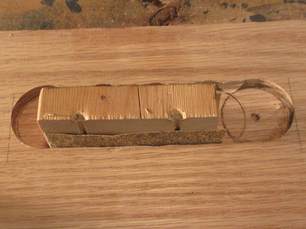
Even though I cut as close to the edge as I dared with Mr. Dremel, I still had some sanding to do. Since this oak is so hard, I started out with 40 grit, then moved up to 60 grit. The plan at this point is to finish up with some 220 and call it a day. But all told, this little project was a success and proof that you don't have to do something a certain way to achieve decent results.
Of course I still have more sanding to do, but the stuff I was sweating over is done. Every other aspect of this project is simple by comparison because it's similar to other projects I've done. I have to round off the edges and then sand and polyurethane the whole business, but for me this was the tough part.

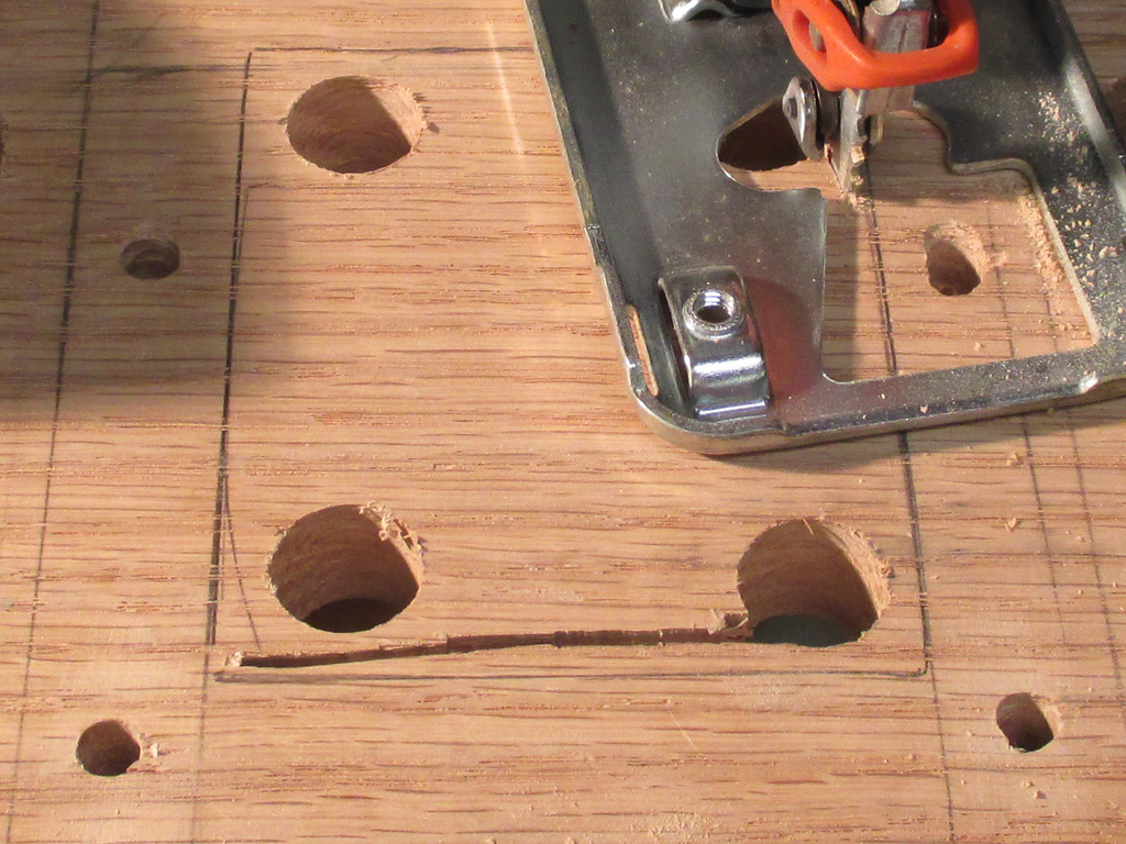
With the oval recess and cup holes roughed in, it was time to make the center cut out which will mate up with the center riser. The center riser will end up being the only component I'll be using from my first efforts at re-imagining this cup holder. This time I simply chucked a spade bit into my drillpress and made myself four corner start holes for the saw.
As you can probably tell, I'm not the most accurate person in the world with a jigsaw. But since I was simply roughing in the opening (later to be fine tuned by sanding the opening), I wasn't too concerned with appearances at this point.
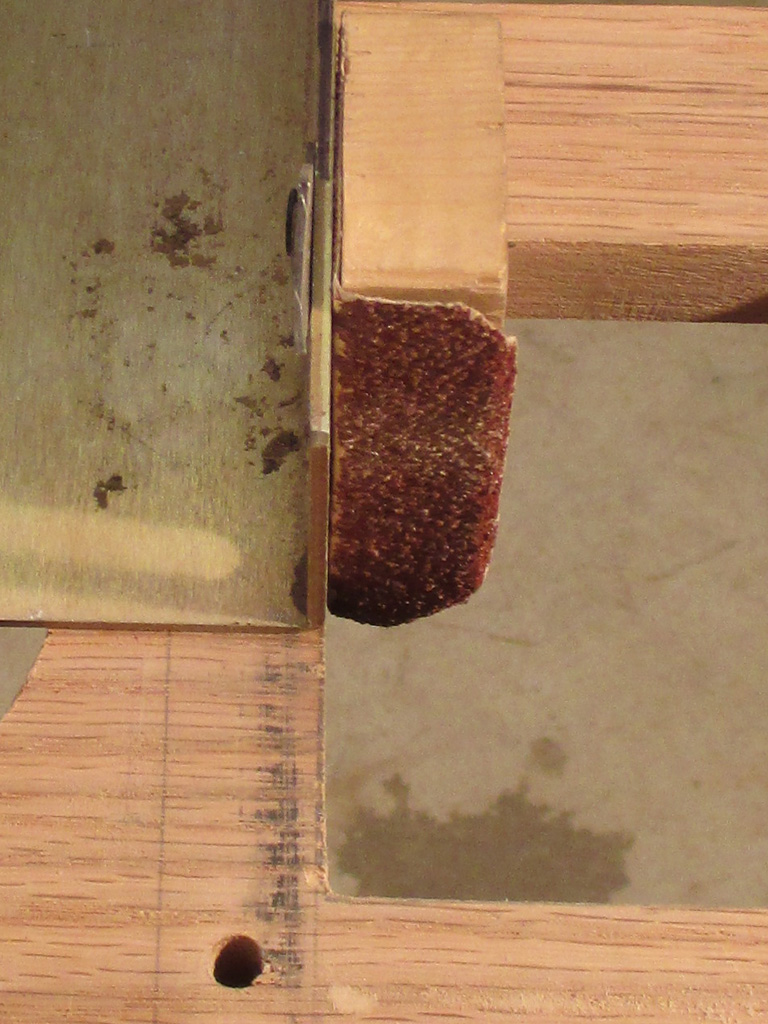
Once again, I started out with 40 grit. Using a small (2"x3"x 3/4 scrap) sanding block, I went to town. Since I didn't want to get too close to my actual dimensions with my "crooked" sawing activities, I had lots and lots of sanding to do. I took some 5" self-stick sanding disks and cut them in half to use on my sanding block.
Gradually I snuck up on my pencil line (and switched to some 150 grit paper), so I needed a way to keep the opening square and perpendicular to the surface. So I came up with this little invention. By screwing the sanding block to a piece of aluminum angle stock I had laying around, I came up with a pretty neat little sanding rig. When I was finished I ended up with a nice symmetrical opening in the wood.
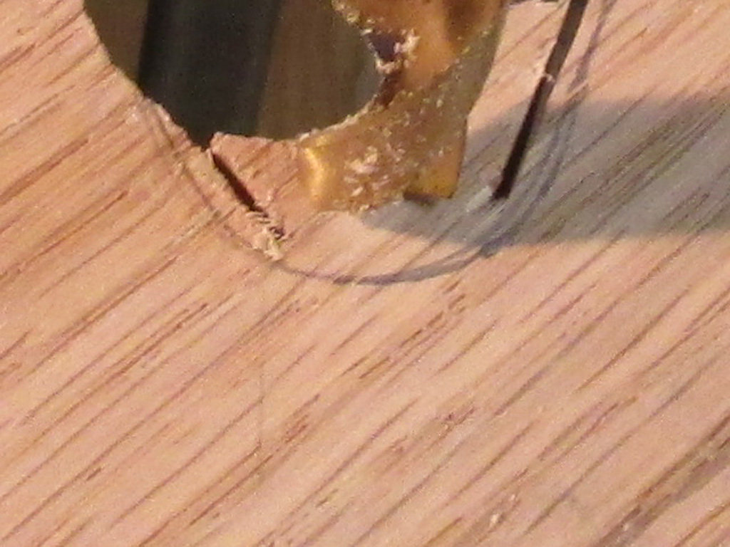
With the square center opening finally meeting my exacting standards, I returned to the cup openings. I used the jigsaw to cut two small lines and then drilled some to remove most of the wood from my target area. Then I used a flat blade screwdriver to snap out the waste material.
All that remained was to use the drum sanding attachement on my Dremel tool to smooth and taper the openings and I was one step closer to completing my work on this top piece. It's taken me quite awhile to get to this point (pricey drillbit purchases and exotic tool inventions notwithstanding), since I'm only able to devote a spare hour here and there, which really slows my progress.
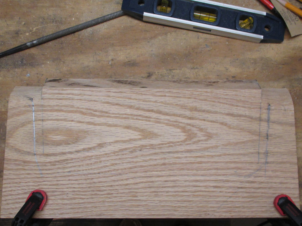
Work continued on my new bottom shelf and I discovered that the engine cover (upon which this will rest) is angled up from the rear towards the vertical surface leading up to the radio. This means I have to cut two angled depressions in the wood (corrosponding to the edge ridges of the engine cover), so the bottom shelf will sit level. Since the center riser and top shelf both sit on the lower shelf, getting things level is paramount.
I measured and marked the inside ridge line, then set the bottom shelf in place and traced the outline of the outer ridge line of the engine cover. With my marks in place I now had a 1/2" wide ridge to cut in the bottom surface of the lower shelf. Once again I turned to my ever versatile Dremel tool for a solution.
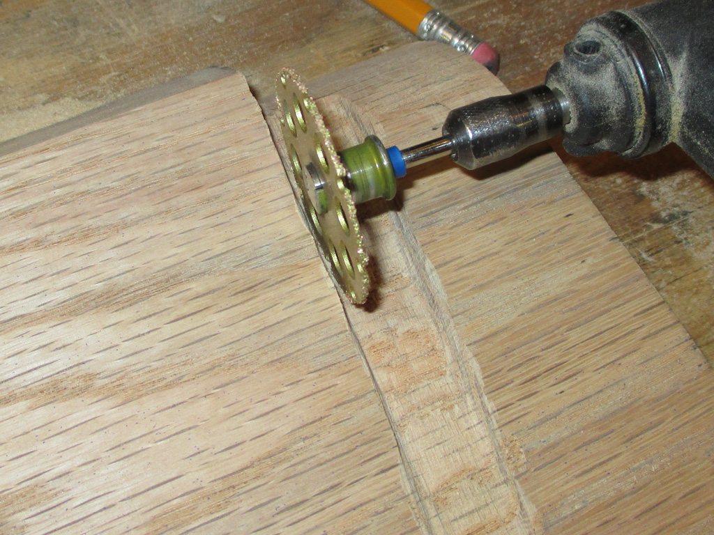
Attempt number one saw me using a drum shaped stone that was roughly the proper width for this phase of the project. The problem was that the stone was too smooth and at higher speeds was just burning the wood. DRAT! Then I spied the cutting wheel sitting in the dremel case and the wheels started turning.
What if... what if I used the cutting wheel as a gouge, slowly moving it back and forth sideways to remove the unecessary material? It wouldn't be pretty or smooth, but for this particular purpose it doesn't need to be. Turns out I picked the right attachment for the job, since it removed the material quickly and with careful manipulation I was successful.
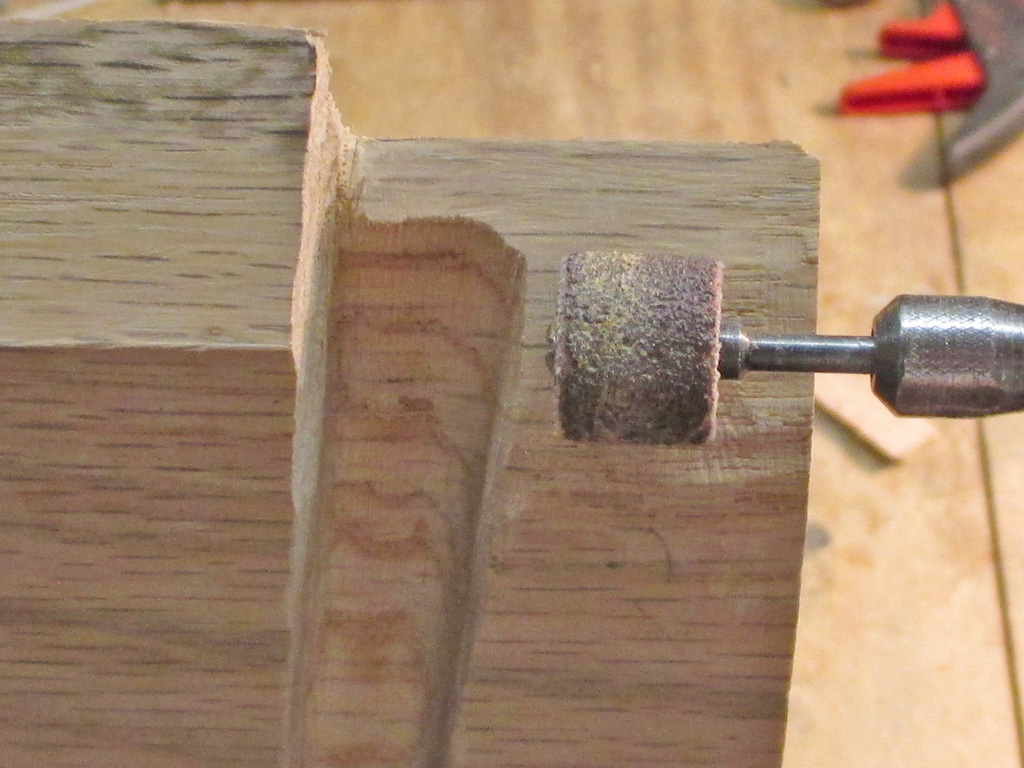
After numerous trips back and forth to the van to measure my progress, I finally had the necessary furrows cut in the wood. Then it was time for more fine tuning. The front edge of the shelf wasn't quite mating up properly to the dashboard, so I broke out the drum sanding attachment and tweaked the curved front lip of the shelf. Little by little I sneaked up on the proper fittment of this edge as well.
I'd really be lost without my Dremel tools. That's probably why I have 3 of them. Right now two of them are sidelined with bad switches. I've bought replacement switches for each, I just need the time to install them. Thankfully, tool number 3 keeps right on keeping on!
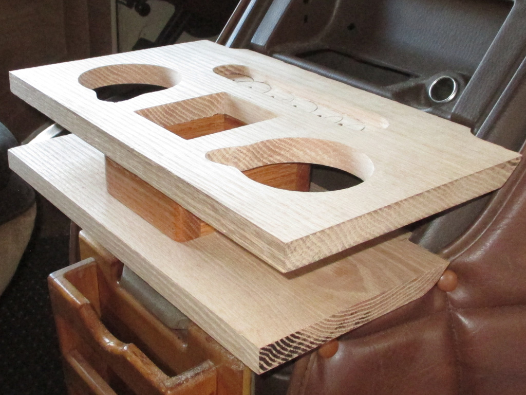
By the time six o'clock rolled around, I began wrapping things up for the day. But first... one last test fit to see how things were lining up. I have to say that I'm pretty impressed with my efforts up to this point.
I still have to round off the sharp corners, sand the flat surfaces and trim the rear edge of the bottom shelf (so I can reach the glove box knob), but overall things are really shaping up. I think the finished product will look close to original and provide me with a unit that will meet my needs functionally.
Of course now I'll need to lower the quilted vinyl overlay (which my shelf now rolls over the top lip of), so everything will look like it was done cohesively and not just thrown together. Oh well, modify one thing and you end up needing to modify everything else adjacent to it I guess. Could be why most vanners say their van is never finished.
With the bottom shelf in place (see above photo), access to the factory glovebox is nil. So, I either shorten the shelf or find some way to give myself some finger access to the glovebox knob. I decided I could afford to shorten it just a bit, so I trimmed off 1/2 inch and test fitted the shelf again. Nope. Not going to work.
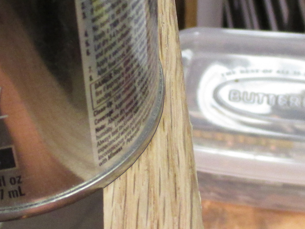
RADIUS PREP
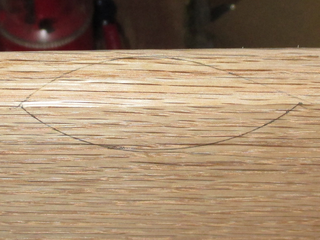
PENCIL EYE
I made a mark on the wood corrosponding to the center of the knob, which is also the center of the shelf itself. I grabbed a small can (using the bottom of the can as a radius) and marked the front and bottom surfaces where I would need to make my cut. I used a coping saw to make the rough cut, staying well within each pencil line so I could sneak up on the diameter with my sanding drum. It may not be perfect, but in use no one's going to whip out a contour gauge and check the thing.
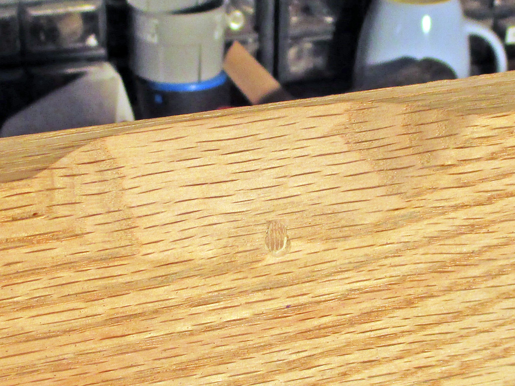
With the grooves already cut in the bottom, this latest change created a ripple effect of sorts. Originally, the center riser was mounted with two screws, one in front and one in back... right smack in the middle of where I need to cut my radius in the wood. So before I did anything, I drilled two new holes (left and right this time) to mount the center riser. I also cut/shaped two miniature dowels out of oak and filled the old holes, using wood glue.
The "dowels" aren't perfect (showing end grain) but I used what I had on hand to try and make it right. I wanted to use real wood and not the Plastic Wood I would have typically reached for. I may have to reach for it yet, just to try and improve the appearance of the thing, but it is functional and not in an obvious location on the shelf.
I used a drum sander attachment in my 'lectric drill for most of this operation, then moving on to hand sanding as I got close to my marks. I eyeballed it this way and that, even checked it with my own contour gauge until I was satisfied that it was as good as I could make it.

After trimming 1/2" off the rear edge of the lower shelf (and cutting in a relief for glove-box-knob access), it was time to work on recessing the coasters. If I had just waited until I had purchased these, I wouldn't be doing the bottom shelf over for a second time. I "guesstimated" the size of the coasters and I was way off the mark. Turns out each one is 4" in diameter and I hadn't left nearly enough room on the bottom shelf I'd created.
Once I had the "Thirstystone" coasters in my hot little hands, the problem became as obvious as the solution. Make another trip to the big box store for another piece of red oak and do the job properly this time out.
With both shelves and the center section in position, I chose a can close to the size of each cup opening, to help me center a coaster beneath each. After checking the placement a couple of times (using my highly calibrated eyeball technique), I traced around each coaster with a pencil.
So, I have two 4" recesses to create. My hole saw blades all have a centering drill bit that would penetrate all the way through the bottom shelf which I did not want. I also needed a hole with a flat bottom for the coasters. Once again it was time for my Forstner bit to step up to the plate.
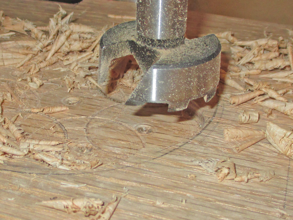
DRILLING IN PROGRESS
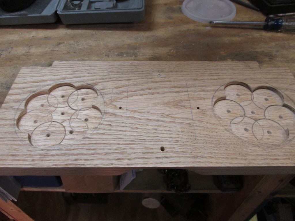
DRILLING COMPLETED
By drilling several overlapping holes within the circle I had drawn I was able to remove the wood and have a flat bottom. I stayed well within each pencil line so I could sneak up on the diameter and have a reasonably tight fit. One thing about Forstner bits, they throw shavings all over the place.
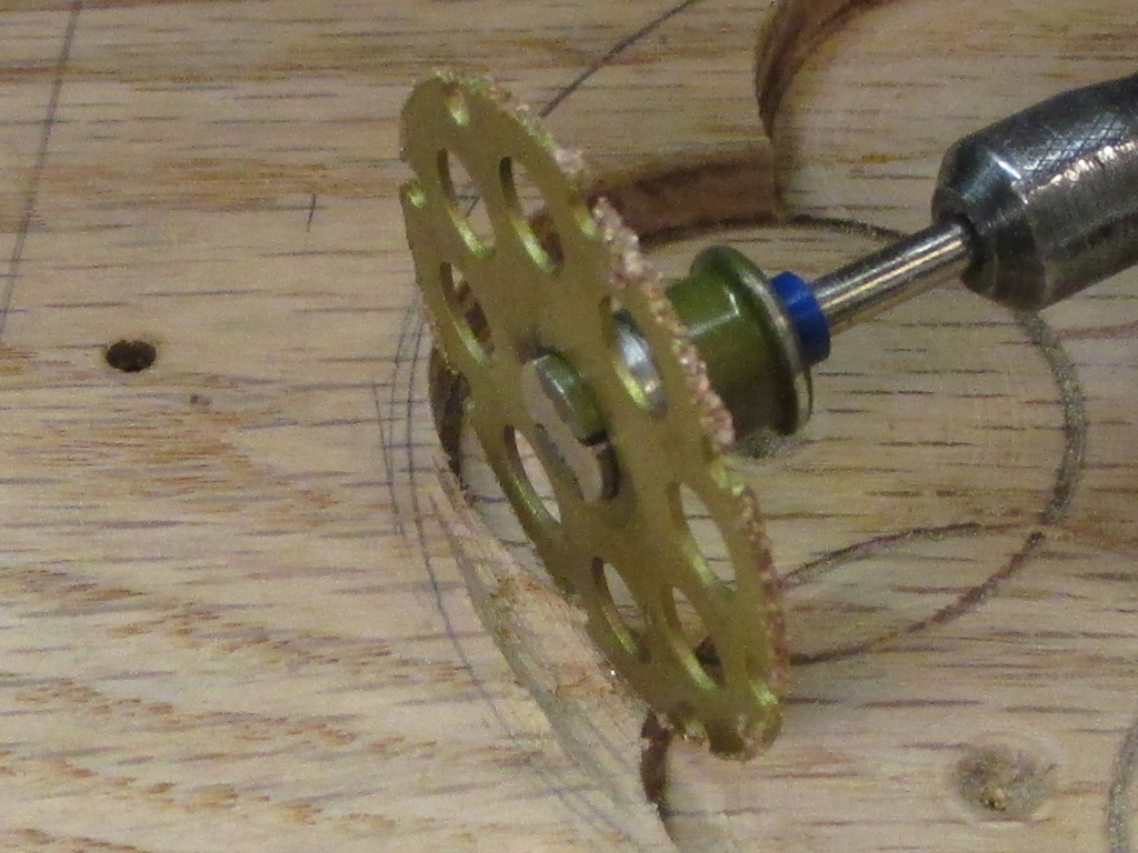
The tricky part here was to not drill so deep as to cut into the grooves I machined in the underneath side of the bottom shelf. Originally, the coasters were going to be flush with the surface of the wood. I measured the thickness of the coaster, divided it in half and set my drill press for that depth which was 3/8's of an inch.
Of course just as before, I'm left with small wedges of material that need to be removed for the hole to become perfectly circular. That's where my trusty Dremel tool comes in. Once again, my $20 carbide tipped cut off wheel really earned its keep as a circular trimming tool.
As a "perfectionista", I'm sorely tempted to try and drill deeper so the coasters will sit flush with the wood as originally envisioned. However, knowing my luck, I'd go through the wood and I'm not about to start this project all over again just for being needlessly anal. Besides, the coasters will be easier to grab this way if I need or want to swap them out. At least that's what I keep telling myself.
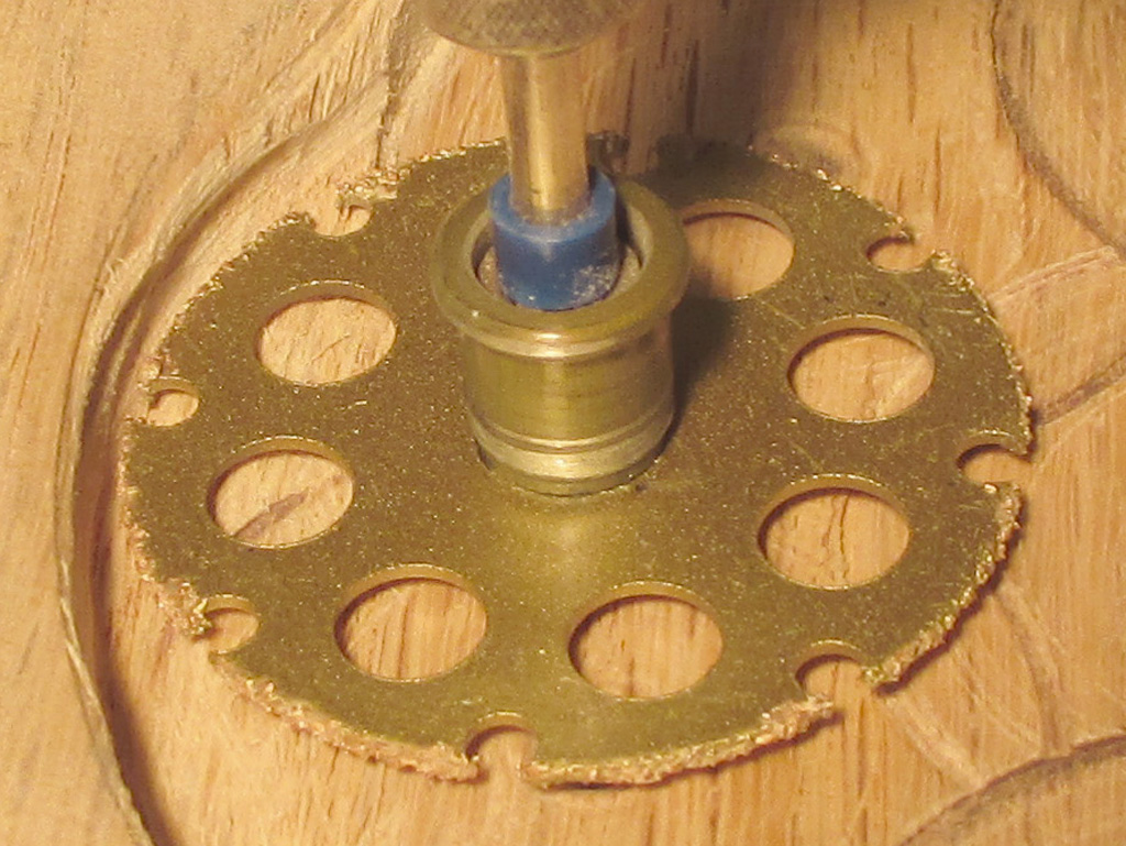
With the wedges mostly ground down, I rotated the cut off wheel 90* and began trimming the remaining waste wood right up to the pencil mark. I stopped frequently and checked the fit of the hole against the coaster to make certain I wasn't going too far too fast with my tools. This is where you need to have a rock steady hand and make sure your work is solidly clamped to a workbench.
As I was finishing up the second 4" hole, the cutting wheel was wearing down and started "grabbing" the wood. Oh well, next time I'm in one of the big boxes I'll pick up another, especially now that I know how handy they are on a woodworking project.
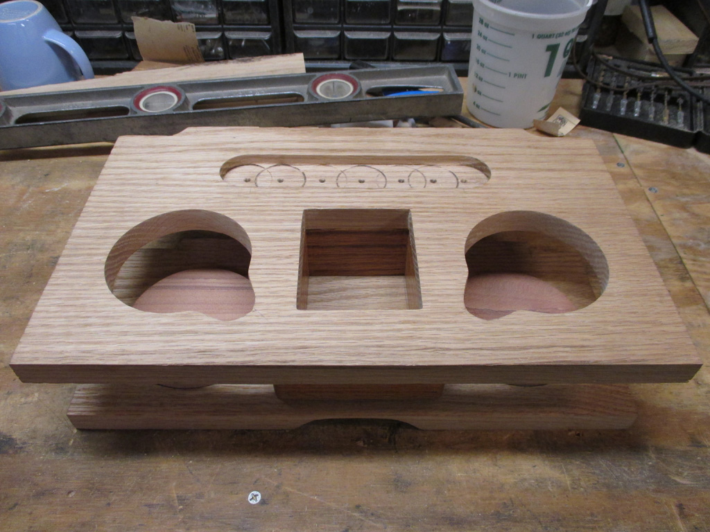
Another super-productive day left me at this point. I'm really coming into the home stretch now! It was a little after 6pm, and I was getting tired at this point, so it was time to stop before I made any mistakes. Thankfully my carbide-tipped cutting wheel lasted until the last recess was completed.
At this point I think I'm down to my last two modifications before I can lay down some polyurethane to the completed unit. I still need to round off the four rear corners and then break out the router for a 1/8 roundover finish to the edges of both the upper and lower shelf. The router is going to be a challenge, so I'm definately going to test my technique on a scrap piece first.
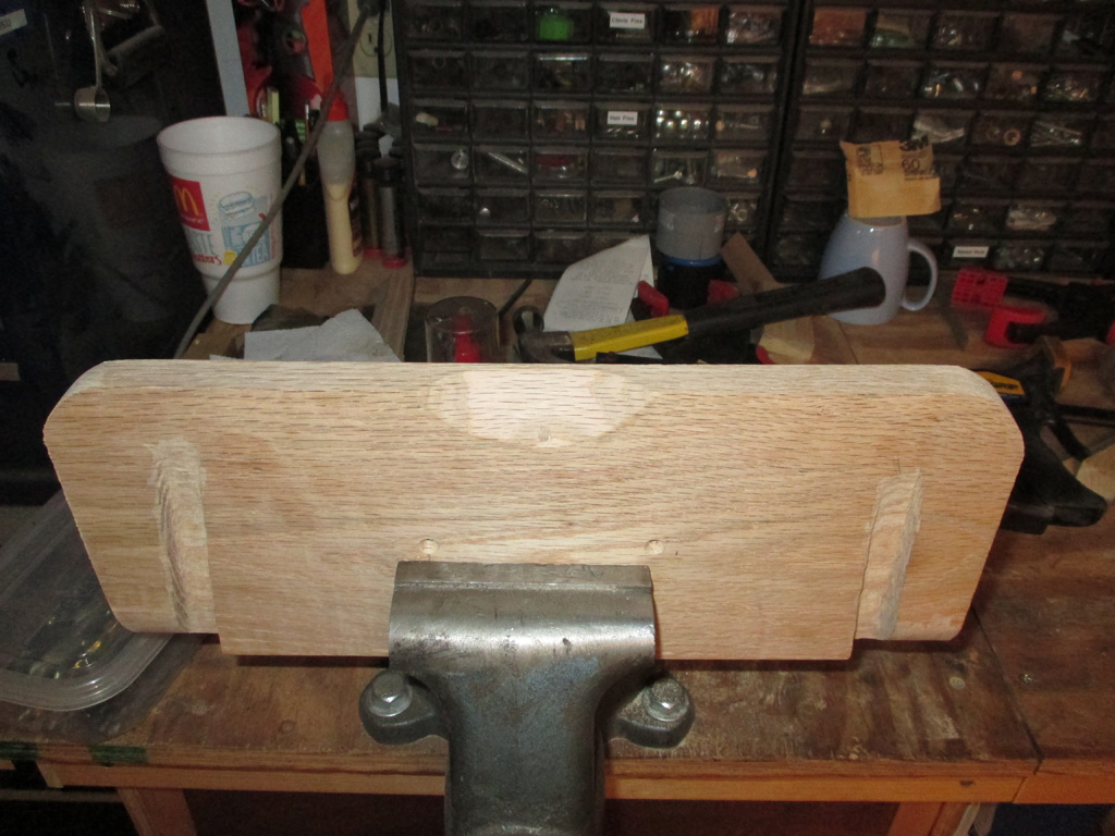
I ended the day by rounding off the edges of the shelf. I need to round off these edges, sand all the surfaces with 220 grit and use the router to round off the longer edges. I mounted my new 1/8 roundover bit in my router and tested it out on a piece of scrap pine. This helped me dial in the depth setting of the router.
I was rather surprized at how smoothly this aspect of the project went. The roundover bit with the bearing on the tip worked just as it should and will give a nice professional edge to both shelves. I may have to touch it up a hair with some 220 if I get too much tearout, but I'll burn that bridge when I get to it.
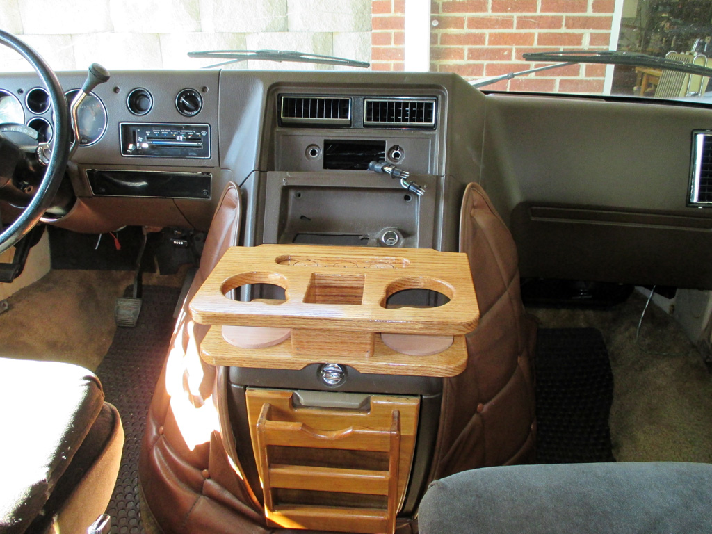
With all of my finishing touches completed and the unit final-sanded with 220 and thoroughly vacuumed, I gave everything 2 coats of clear polyurethane. Even though nothing has been glued up (and I don't have the cork installed at this point), I couldn't resist a look-see to gauge how things are shaping up. I must say I'm rather impressed with my progress up to this point.
The red oak coordinates (particularly with the document caddy beneath it), much more closely than the original Mark III unit. I'm still not sure why exactly, but a previous owner may have changed things up between ordering the van I scrounged these parts from and the time he junked it. Regardless, I really like the way the grain pops with the poly.
7 Months Later - Done!
With two more coats of poly (sanding everything with 220 between coats, which took forever), the next step was to install the cork. No pictures of this part, I'm afraid. Cut the cork with a utility knife, traced around a socket for the rounded ends, trimmed those with an X-Acto and sanded the curved ends ever-so-lightly with my Dremel. Turned out pretty good even if it did take me 6 months to build.
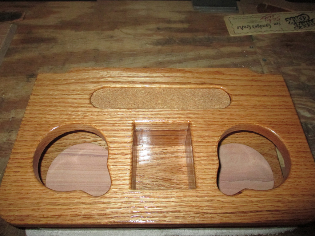
THE REESE SPECIAL
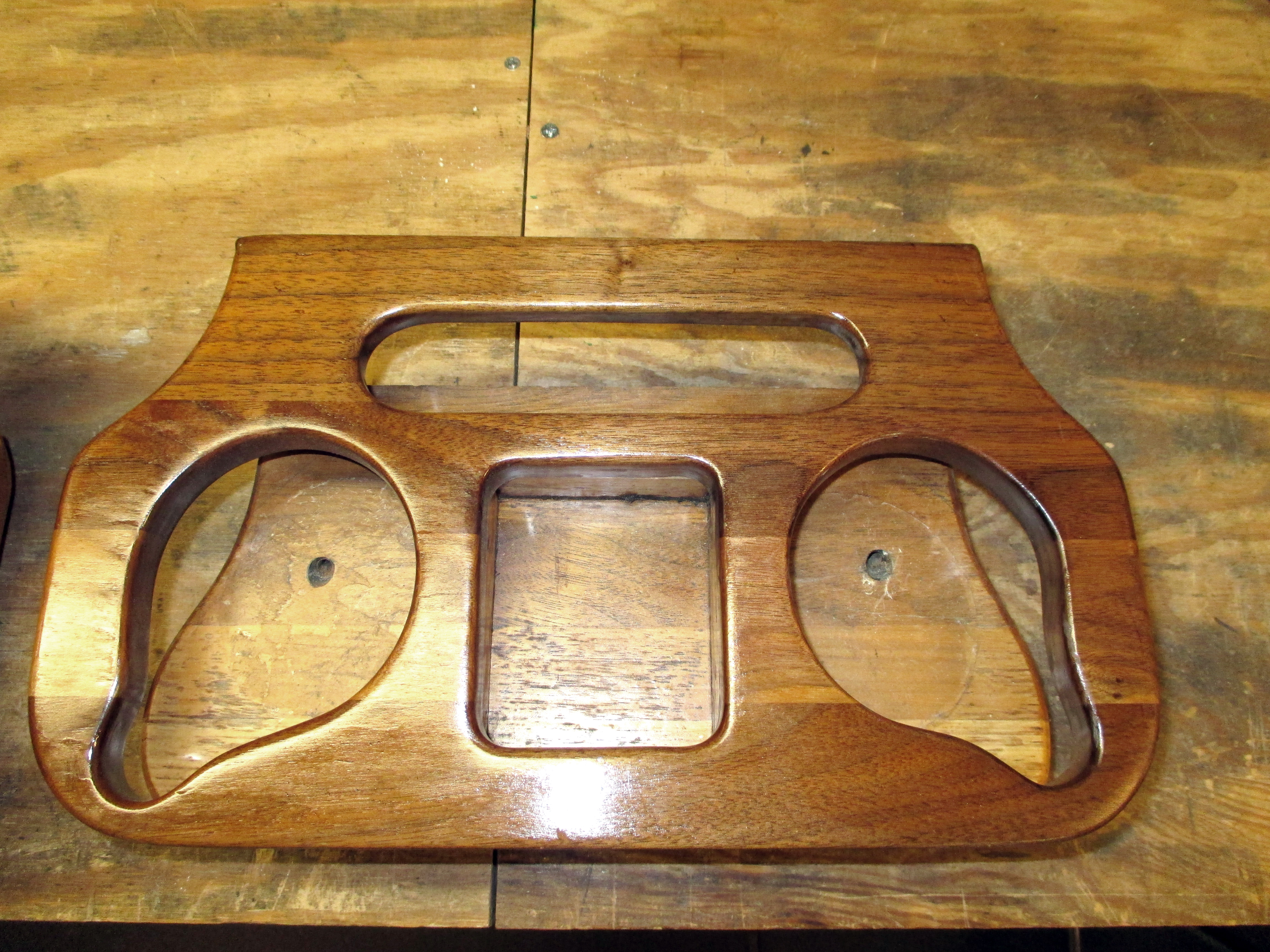
MARK III VERSION
One last shot of my "model" (on the right), to illustrate how I re-interpreted it. My new version is only 1.5 inches wider, allowing space for me to spread the holes slightly. The lower shelf is wider too, giving me room for the coasters. The two mounting screws of my unit will now be hidden beneath the coasters for a cleaner look. Why would someone design a cup holder out of wood, that a sweating cup or glass could ruin over time? Ridiculous!
The Vulture
Winter 2013/2014
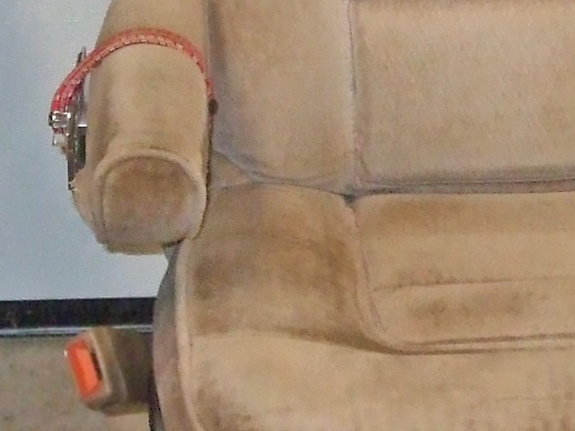
In scouring the list that is Craig's, I found my previous donor van still listed! I have never been able to get the front passenger safety belt to work properly. The add stated each seat was $40 bucks, for that price I grabbed my tools and headed back over to this guys place for one last go 'round. My return visit found the thing pretty well picked over (all but the front doors [which had accident damage] were gone), so I'm glad I made the return trip.
The seats aren't nearly as nice as my flash photography makes them out to be. I plan on using the bases and seat belts, mating them to the captain's chairs already in my van. As an added bonus, the driver's seat is a 8-way power unit!
First things first. I procured trim pieces and pleated window shades for both rear doors from the wrecked GMC I drilled 3 mounting holes for each side and PRESTO... the rear doors of my van now look professionally finished and have the ability to provide some privacy should the need arise. A couple of pleats are slightly catywompus, but that's okay.
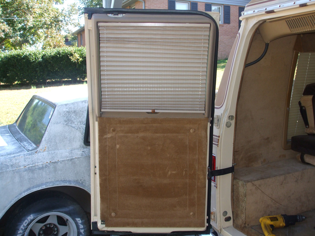
DRIVER'S SIDE
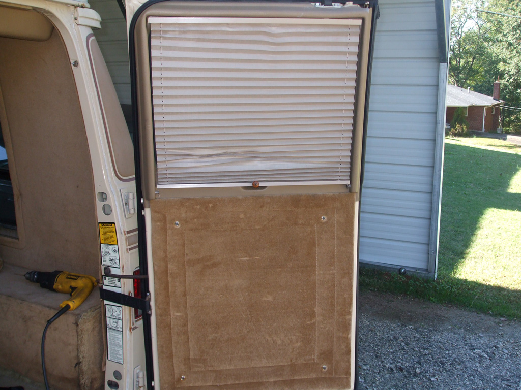
PASSENGER SIDE
Took me all of 10 minutes per side. Remove lower panel (because top trim slides behind it), hold lower panel in place (slightly lower), and drill some holes. Snap the trim caps back in place and things have shaped up quite nicely. The color of the window shade trim pieces was nearly a perfect match to my interior to boot. Booyah!
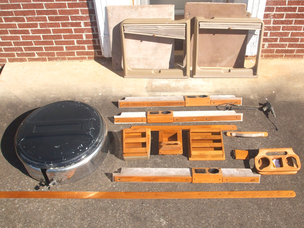
I seem to have a 6th sense when it comes to hunting for stuff on Craig's list. I discovered a wrecked '95 GMC conversion van being parted out about 1/2 hour from my house. One thing that my van was missing (particularly for an overnight stay in a campground setting), was a way to have some privacy. My van has blinds, but three of them have issues with damage of one kind or another and the back windows have no provision whatsoever for attachment of any sort of window treatment.
The van on Craig's List had been bought for its drivetrain and the owner was parting out the rest. I spent about two hours removing all the oak trim I could manage as well as the factory rear window trim panels with integral shades. I did discover that this newer conversion van had its walls insulated with unfaced pink fiberglass. Mine only has empty wall cavities which provide no barrier against the sweltering southern summers. Oh yeah, I almost forgot... I finally scored a spare tire cover that I'd been hunting for since purchasing the van. Total: $60 bucks. The cheapest spare tire cover I'd found previously was at least $100, so I'm pretty happy with my Saturday morning haul.
December 2013
Overhead Console Upgrade
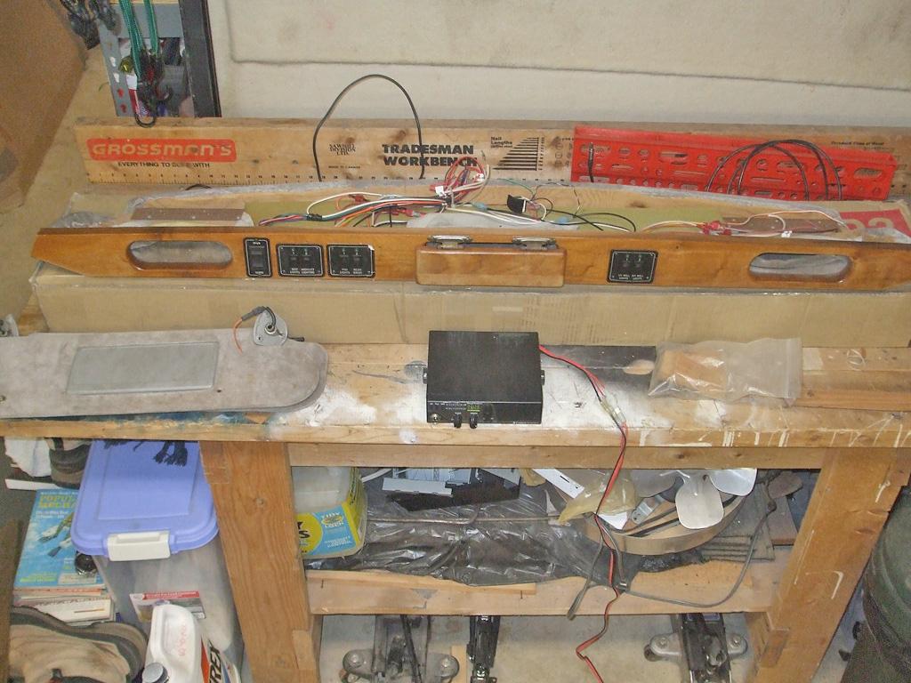
I started out running new rear speaker wires to my new rear speakers. That was my initial objective. The overhead console got involved because the original console housed the two front speakers for the radio and the switches for the interior lights. After much rumination over the situation, I decided I'd rather have overhead storage instead of speakers. I've already got replacement speakers to install in the dash (from before I discovered there were overhead speakers in the console), so that's no problem.
Rather than rebuild my vans original console (practically from scratch), my speaker decision triggered another, and I purchased an overhead console out of a a mid-90's Chevy Gladiator II conversion van, found on the Bay of E. Granted, I'll have to reupholster it in my vans colors (with fabric previously purchased for just this purpose), but I scored the console, padded sun visors with extensions and lighted mirrors, wood fascia, switches, storage pockets and mounting hardware for a pretty reasonable "buy it now" price. Before long, I'll be on my way to a more sophisticated (not to mention functional), interior. I hope.
While I'm At It...
(Oh no!), the interior lights will never be as easy to rewire as they are right now, so once again I got sidetracked. I'll replace the PO's cobbled together speaker wires (which he used to power both the lights and the speakers), some of the smallest gauge wires I've ever seen! I'm surprized the van hasn't burned down to the ground long before I got my grubby little mits on it. I'll be running 14 gauge wires for the lights and change them over to LED style lights while I'm at it. Less draw and bigger wires = much safer van to travel in with the family.
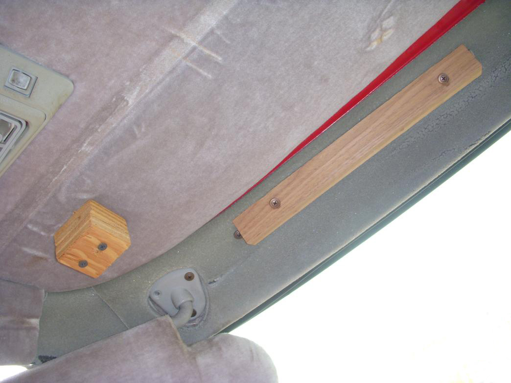
ORIGINAL MOUNTS
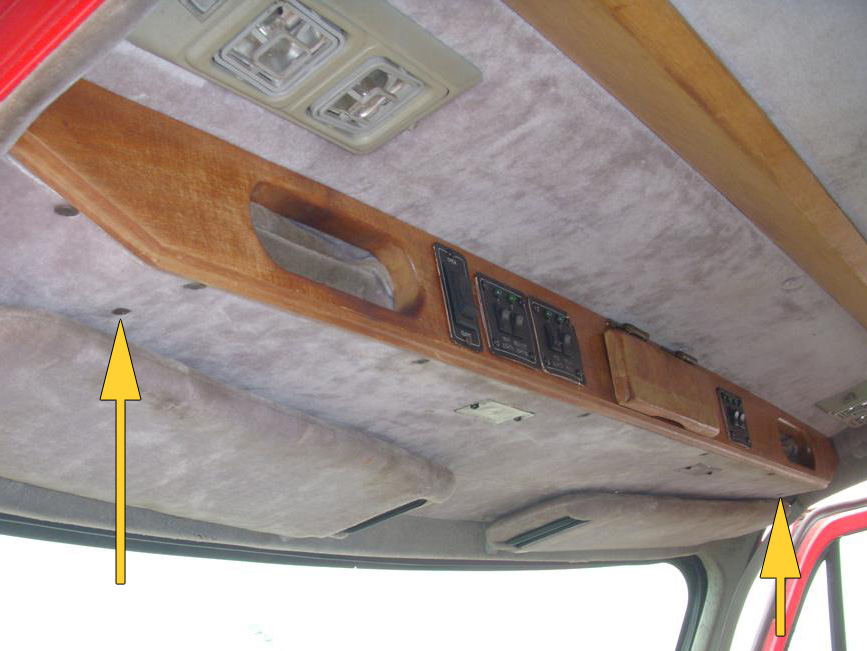
AS INSTALLED
A couple of shots I "borrowed" show how the console was mounted in the conversion van that was parted out. The center compartment (sans spring-loaded lid), will be the future home of my CB radio, which I'll mount using a cover plate that can be resized if need be without cutting into the wood of the console. The arrows illustrate how the rear of the console was mounted previously. Only I can take a simple re-wiring task and turn it into a major overhaul of the whole interior of my van. At least when it's finished I'll have things arranged to my liking and have switches, wiring and accessories that will actually be fully functional.
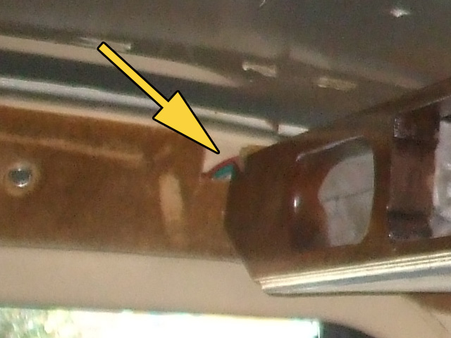
Here's the new unit, which I am modifying to fit my van. The console my van came with intruded too far into the driving space and had a haphazard location for the switches and accessories. Now... I'm going to fix that.
At this point, I've modified the openings in the fascia to accomodate my new switches, the original (to my van) LCD clock and my new Cobra CB radio. With everything sized properly, I sanded the whole thing and gave it several coats of clear polyurethane for protection. The end pockets on each end will be retained for storage. Not sure yet whether or not I'll make new pocket openings with my brown fabric or not, but that can wait. Right now my chief concern is getting the console fitted properly to my van.
With that in mind, I remounted the grey fill panel to the refurbished front fascia and mounted both front wood brackets to the panel. This way, once I have the console in position, I can reach through an opening with my Sharpie and mark where the brackets meet the steel over the windshield.
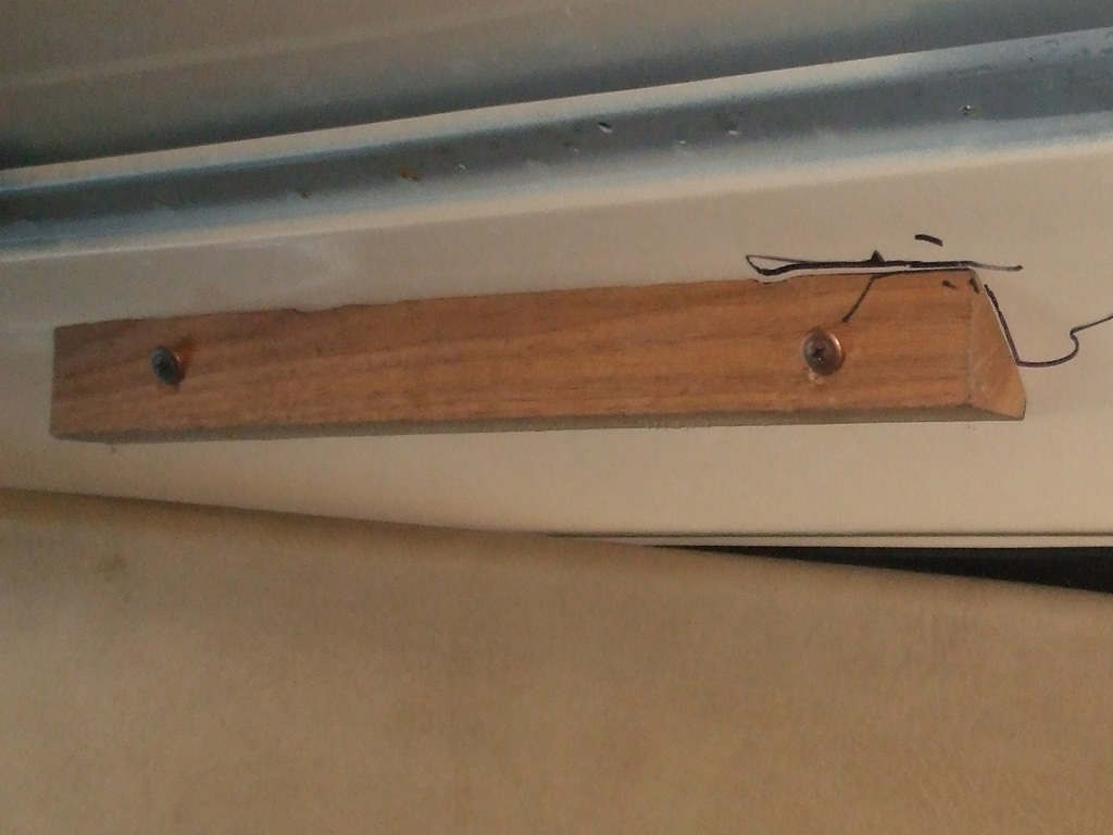
Then I'll remove the console, remove the wooden brackets from the panel and install them inside the marks I've made on the steel over the windshield. Since I could only reach the inner most side of each bracket, I had to modify my original plan. With the inner corner of each bracket marked, I held the bracket up to the mark, drilled one hole, leveled off the bracket and drilled the second hole. As long as both brackets are level, I should be good to go as far as the front mounting points are concerned.
Then I can re-install the panel to the brackets and presto! Everything will line up perfectly... uh... I hope. The back edge of the console was mounted with two long screws just forward of the fascia panel. Two one inch plywood squares were used as shims on each side. Once I get the new headliner mounting boards and headliner mounted, I may have to make some adjustments, but nothing I can't handle.
With everything centered up to my liking, including equal measurements of distance form the windshield, I checked the sun visor clearance. The passenger side actuallly lined up pretty good. The driver's side left me no room whatsoever for getting a screwdriver in place if I needed to and the visor rod was right up against the material of the filler panel.
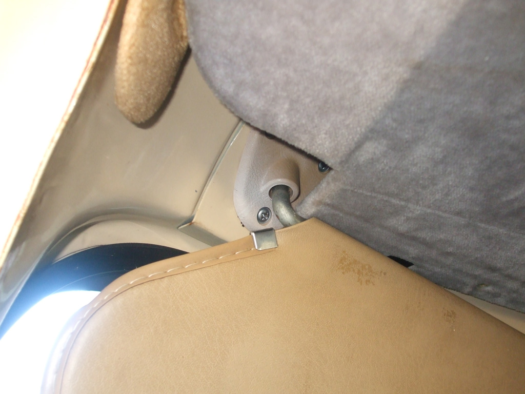
LEFT SIDE
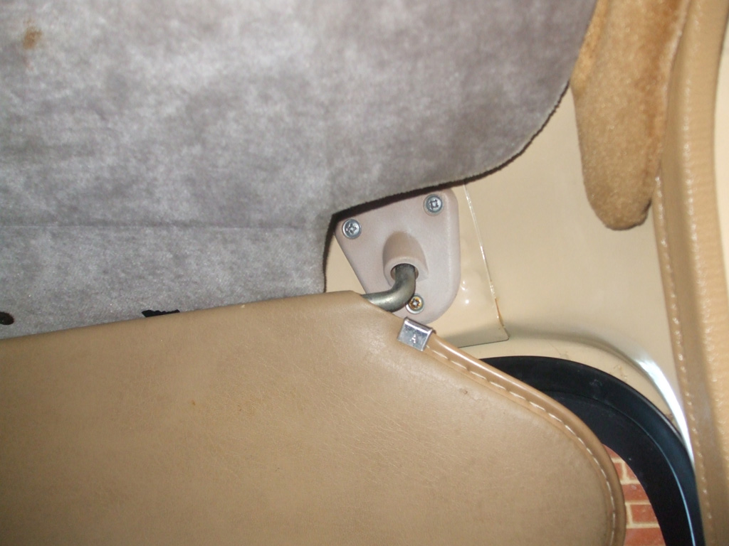
RIGHT SIDE
This means that I'll have to remove the fabric covering (which I was going to do anyway) and trim the plywood filler panel to give myself some more clearance. Then I will mock up everything one more time to make sure I have the clearances I want, then I can reuphulstor the filler panel with the fabric that will match my van's interior.
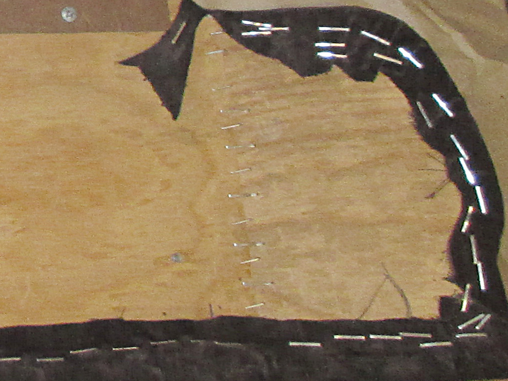
I used a screwdriver to painstakingly remove all the old staples and grey fabric from the plywood. I did this so I could study how they folded the fabric to go around the corners when they installed the original fabric and it gave me a pattern to use for the new fabric. I removed the old foam, sanded off the old glue, applied new glue and new cotton batting to the plywood. I was way too busy to take any shots of this part of the operation.
I cut the new headliner fabric, and sprayed both the cotton batting and the back of the new fabric with the 3M upholstery adhesive (27 bucks a can!), I purchased specifically for this purpose. I carefully laid the fabric over the batting, smoothed the fabric with a wooden roller and flipped the whole thing over to begin the stapling of the new fabric to the plywood.
With the fabric stapled in, I made a cutout in the plywood where the CB speaker will be for better sound transmission. The original conversion company laid down a thin layer of foam on the inside (for reasons unknown), so I did likewise which helped support and level the CB radio and might help protect the wires.
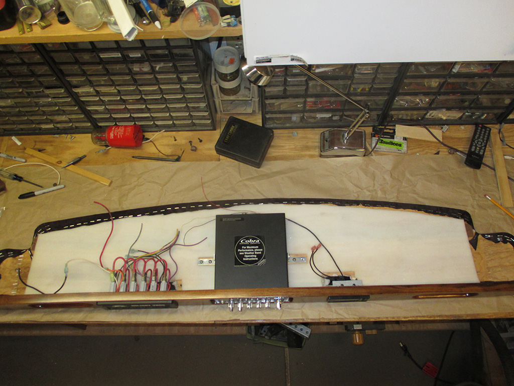
With the foam in place, I made the necessary cut-outs for the CB speaker and courtesy lights as well as the CB support brackets I'd fabbed up previously. I spent a great deal of time mocking up the switch panel (which was purchased separately from the console) and making sure the courtesy lights did not interfere with the wiring of the switch. This was due to the fact that I replaced the courtesy lights that came with the console with nicer ones I had on hand.
The hard part was drilling holes (should've been done prior to fabric install), for the CB bracket WITHOUT going too deep and catching the fabric, or worse, going through it! Then I had to root through my parts organizers to find screws that were the right diameter and thread pattern, but not too long. I ended up pulling it off with only a slight bulge in the fabric (because I know it's there?), from the screws pressing on the plywood from above.
All that remains is for me to make new pockets (for the outer oval openings) out of my new fabric. This will probably be a good indoor winter project to finish off the console prior to installation. I plan on using an old one as a pattern, cut the fabric to size and commandeer wife's sewing machine to complete the operation.
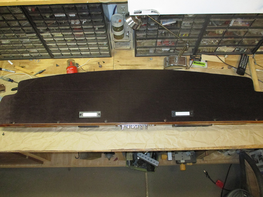
Here's a shot of the unit showing what you'll see once it's installed. I replaced the original map lights with newer ones, which are in better shape and have opaque lenses instead of clear ones. These I'll wire up to turn on when the doors are opened. The original overhead swivel lamps will be relocated to where they don't hit my head every time I climb into the van, probably moving them inwards and farther back on the headliner.
I will use the swivel lamps as map lights, wired to one of the overhead console switches. The goober I bought the van from had them wired as dome lights that came on when you opened the door. I'm a tall guy and hit my head on the driver's side lamp when I bought the van they were so close. I think relocating them will make them more useful to me and far less in the way than they were. Time will tell of course.
Sun Visor Refurbishment
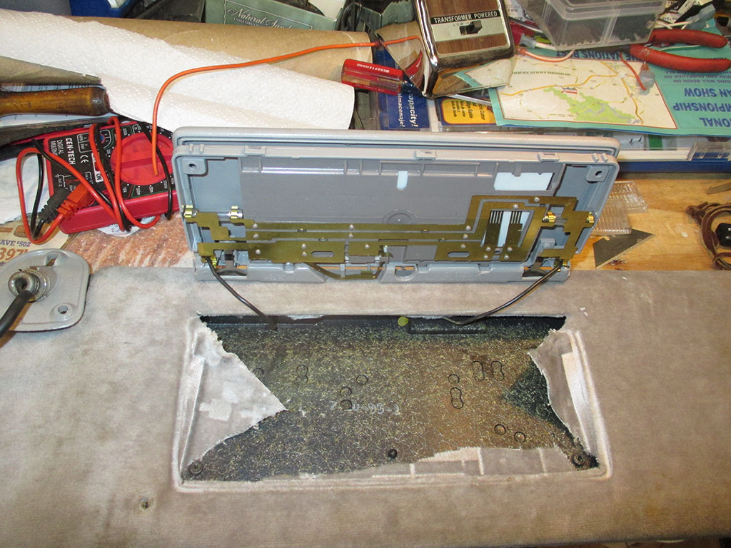
The sun visors that came with the console were upholstered in grey fabric to match the overhead console. That means I have to change the fabric on these two babies to match the console. And that means I have to figure out how the hell to take these things apart. There were two screws near the flip up mirror cover which I removed first. Since that did nothing, I removed the flip up mirror unit next, by gently prying up on the lower edge. My thoughts were that some hidden screws might be hiding behind it, but this was not the case.
The brass-looking grid seen here is what makes the lights on either side of the mirror function. I later ended up taping over these with duck tape after accidentally bending one. I tried bending it back with my fingers, but these are tougher than they look. Naturally I bent the part that holds the tiny fuse-shaped bulb, so I have to fix this. Wonderful. I have some tiny needle-nose pliers I plan to use to fix this when the time comes.
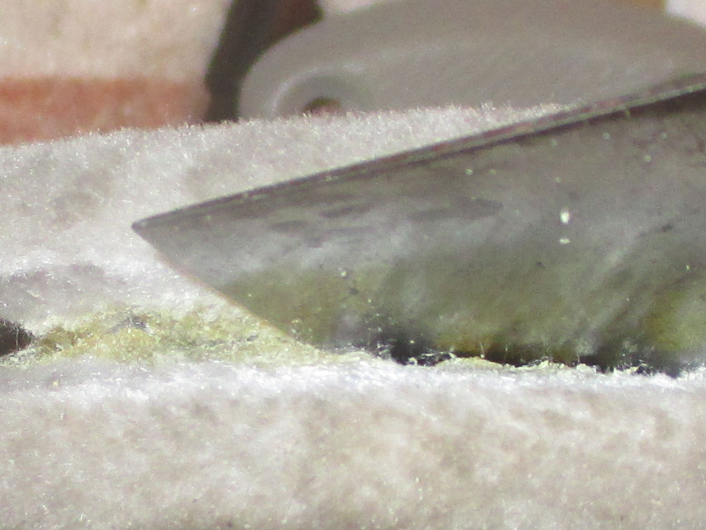
After some gentle exploratory prying, I discovered that these were made in two halves that were glued together after they were upholstered. Once I discovered this, it was pretty easy to go along prying apart the glued edges a little at a time.
This is where having lots of patience really pays off. Especially when working with plastic that's 30 years old give or take. Got to pry a little, grab a light and peek inside, then pry a little more, all the while hoping you don't go too far and hear the dreaded snapping of plastic bits.
I'm not sure what type of glue they used, but it was some downright tenacious stuff to still be holding on with a death-grip after years out in a vehicle. I'll have to look around to find an appropriate adhesive to bond both halves back together. Some sort of upholstery adhesive should do the trick. I hope.
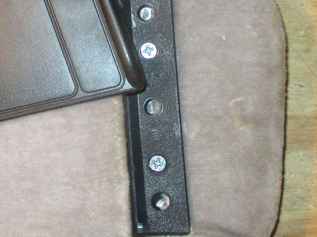
Once I'd worked my way along the edge, I was able to remove the plastic slider that serves as an auxiliary sun visor, by sliding it out past the plastic stops molded in the lower half. That exposed two hidden screws that were holding the edges together where the visor hooks into the center clip above the rearview mirror. I could feel resistance as my prying neared this side of the visor, so I became real cautious and was looking for some sort of hidden fastener. I guess they used these to hold one edge and glued/clamped the rest of the visor when they originally made these.
Finally the last item to be removed is the pivot mount for the visor. On these, the ground wire clips onto the end of the pivot arm, while the positive wire goes through the hollow metal bar. It was fairly easy to unclip the ground wire and thread the pivot arm out through the lighted mirror opening.
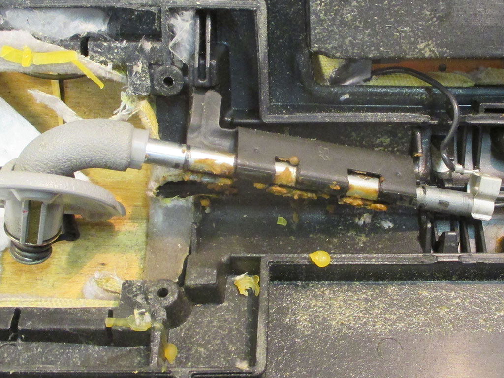
PIVOT FREE
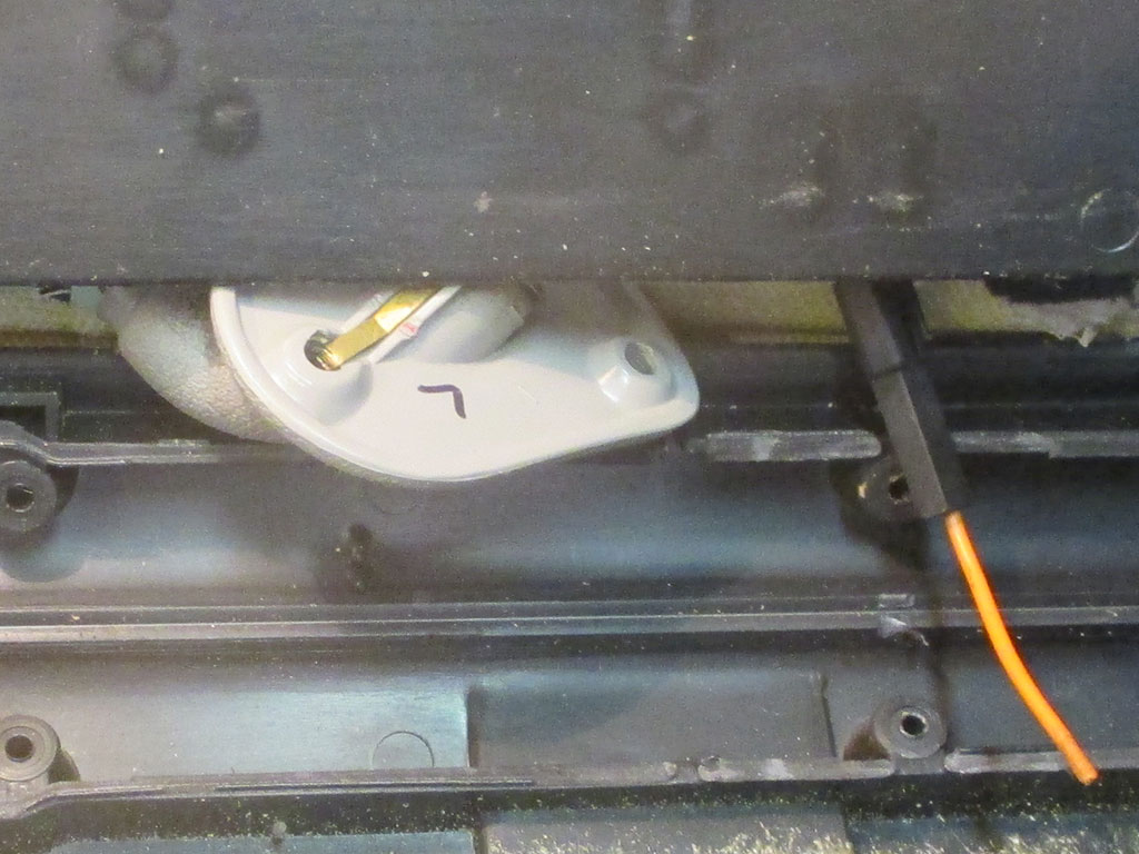
REMOVING PIVOT
I'd been procrastinating over these for some time, but with the console nearing completion, it was time to solve this mystery. Of course once you figure out one of these, the other one's duck soup.
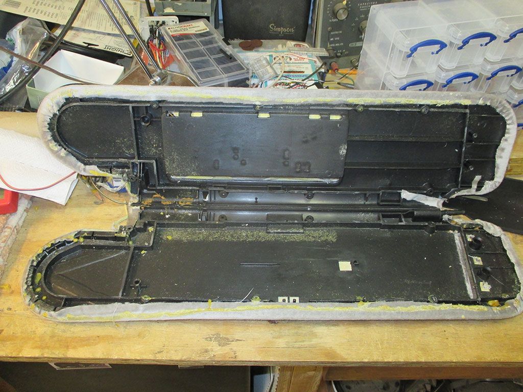
Overall, not a bad way to spend a couple of hours on a weeknight, during an unusually cold winter in the south. With everything taken apart all I need to do is carefully remove the original fabric to use as a pattern for the new material I have.
One issue I'll have to address is the plastic pieces that are seen on this unit. The "dove gray" mirror assembly and pivot bar attachment point are both going to stand out like sore thumbs. My plan is to paint these pieces with some SEM interior paint, brown if I can find it, black if I can't.
I still have the plastic preparation chemicals from painting the plastic bumper extensions on the Caddy, so I'll use the same preparation for these pieces and see what happens. Since I already have black trimmed lights on the console I may just go with black and call it a day.

© Copyright 2009 Brian Petruska | Top | Upgrades | GM Performance Parts | HTML Now! | Apple | Comments |